
L 53
SERVICE MANUAL
MAY 2005
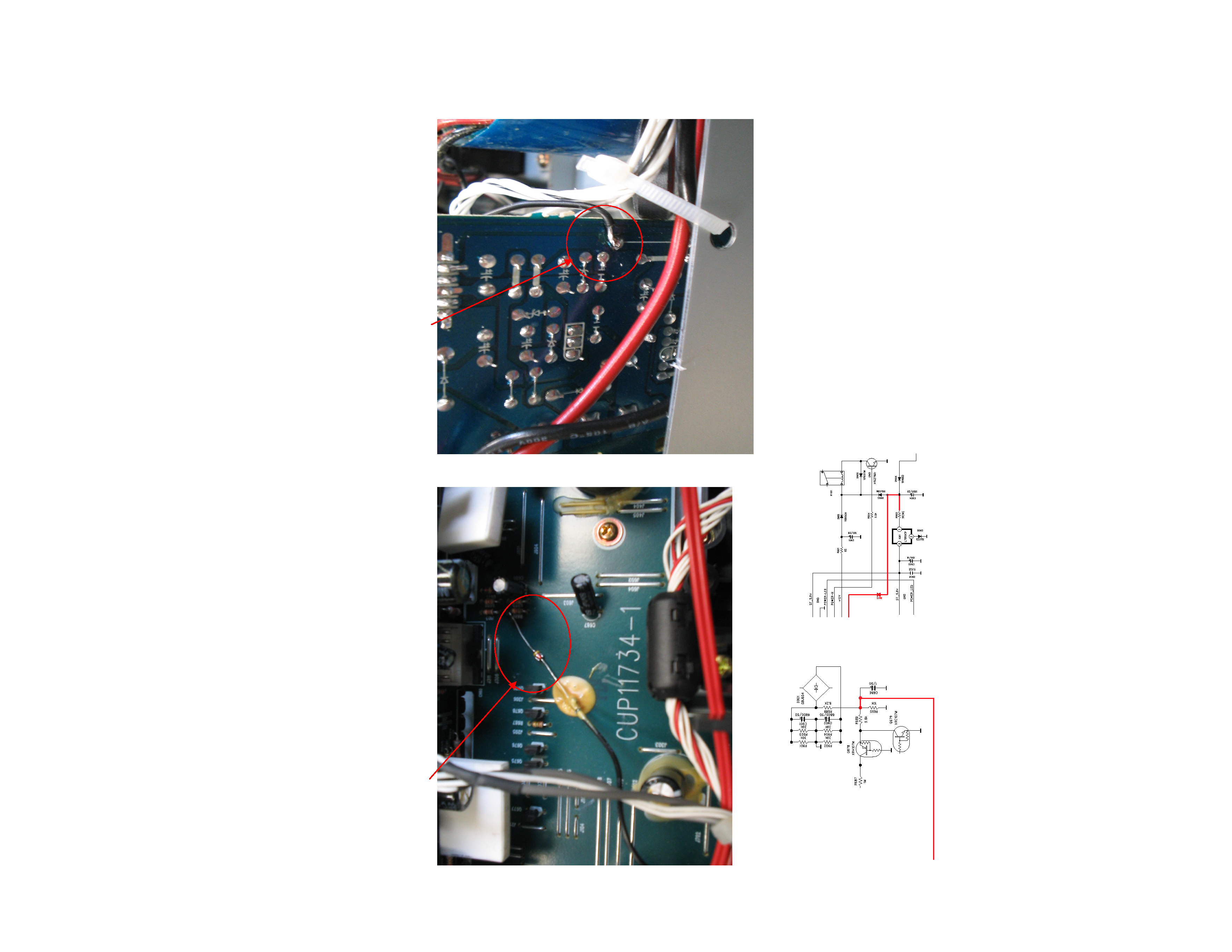
SUBWOOFER MUTING
Install diode on the main board (component side), solder to resistor R689 (figure 1) with a long wire
connected to resistor R903 on the standby power-supply board (foil side), see figure 2
NEW DIODE
1N4148 CATHODE FACING R689
Figure 1
CUP11734-1
WIRE FROM DIODE
ANODE
Figure 2
CUP11732-6
ST_M
1N4148
To CUP11734-1
R689
CUP11732-6
To R903 on CUP11732-6
CUP11734-1