GB
F
D
E
I
S
P
NAD
L 40
STORE
CANCEL
DISPLAY
MONO
BASS EQ
TONE
DEFEAT
RANDOM
REPEAT
VOLUME
TREBLE
BALANCE
BASS
INPUT SELECTOR
SEARCH / TUNE
PLAY
PAUSE
STOP OPEN
SKIP/ PRESET
Compact Disc Receiver L40
PHONES
RANDOM
REPEAT 1 ALL TOTAL
STEREO
RDS
kHz
MHz
PROGRAM
ANTENNA
REMAIN
BASS EQ
TONE DEFEAT
· OWNER'S MANUAL
· MANUEL D'INSTALLATION
· BEDIENUNGSANLEITUNG
· MANUAL DEL USUARIO
· MANUALE DELLE ISTRUZIONI
· BRUKSANVISNING
· MANUAL DO PROPRIETÁRIO
©1998.
NAD
ELECTRONICS
LTD.
L40
NAD
2
Warning: To reduce the risk of fire or electric shock, do not expose this
unit to rain or moisture.
The lightning flash with an arrowhead symbol within an equilateral trian-
gle is intended to alert the user to the presence of uninsulated "danger-
ous voltage" within the product's enclosure that may be of sufficient
magnitude to constitute a risk of electric shcok to persons.
The exclamation point within an equilateral triangle is intended to alert
the user to the presence of important operating and maintenance
(servicing) instructions in the literature accompanying the product.
Do not place this unit on an unstable cart, stand or tripod,
bracket or table. The unit may fall, causing serious injury to a
child or adult and serious damage to the unit. Use only with a
cart, stand, tripod, bracket or table recommended by the man-
ufacturer or sold with the unit. Any mounting of the device on a
wall or ceiling should follow the maufacturer's instructions and
should use a mounting accessory recommended by the manu-
facturer.
An appliance and cart combination should be moved with care. Quick stops,
excessive force and uneven surfaces may cause the appliance and cart combi-
nation to overturn.
Read and follow all the safety and operating instructions before connecting or
using this unit. Retain this notice and the owner's manual for future reference.
All warnings on the unit and in it's operating instructions should be adhered to.
Do not use this unit near water; for example, near a bath tub, washbowl, kitchen
sink, laundry tub, in a wet basement or near a swimming pool.
The unit should be installed so that its location or position does not interfere with
its proper ventilation. For example, it should not be situated on a bed, sofa, rug
or similar surface that may block the ventilation openings; or placed in a built-in
installation, such as a bookcase or cabinet, that may impede the flow of air
through its ventilation openings.
The unit should be situated from heat sources such as radiators, heat registers,
stoves or other devices (including amplifiers) that produce heat.
The unit should be connected to a power supply outlet only of the voltage and
frequency marked on its rear panel.
The power supply cord should be routed so that it is not likely to be walked on or
pinched, especially near the plug, convenience receptacles, or where the cord
exits from the unit.
Unplug the unit from the wall outlet before cleaning. Never use benzine, thinner
or other solvents for cleaning. Use only a soft damp cloth.
The power supply cord of the unit should be unplugged from the wall outlet when
it is to be unused for a long period of time.
Care should be taken so that objects do not fall, and liquids are not spilled into
the enclosure through any openings.
This unit should be serviced by qualified service personnel when:
A. The power cord or the plug has been damaged; or
B. Objects have fallen, or liquid has been spilled into the unit; or
C. The unit has been exposed to rain or liquids of any kind; or
D. The unit does not appear to operate normally or exhibits a marked change in
performance; or
E. The device has been dropped or the enclosure damaged.
DO NOT ATTEMPT SERVICING OF THIS UNIT YOURSELF.
REFER SERVICING TO QUALIFIED SERVICE
PERSONNEL.
Upon completion of any servicing or repairs, request the service shop's assur-
ance that only Factory Authorized Replacement Parts with the same characteris-
tics as the original parts have been used, and that the routine safety checks
have been performed to guarantee that the equipment is in safe operating condi-
tion.
REPLACEMENT WITH UNAUTHORIZED PARTS MAY RESULT IN FIRE,
ELECTRIC SHOCK OR OTHER HAZARDS.
ATTENTION
POUR ÉVITER LES CHOC ELECTRIQUES, INTRODUIRE LA LAME
LA PLUS LARGE DE LA FICHE DANS LA BORNE CORRESPON-
DANTE DE LA PRISE ET POUSSER JUSQU'AU FOND.
CAUTION
TO PREVENT ELECTRIC SHOCK MATCH WIDE BLADE OF PLUG
TO WIDE SLOT FULLY INSERT.
If an indoor antenna is used (either built into the set or installed separately),
never allow any part of the antenna to touch the metal parts of other electrical
appliances such as a lamp, TV set etc.
CAUTION
POWER LINES
Any outdoor antenna must be located away from all power lines.
OUTDOOR ANTENNA GROUNDING
If an outside antenna is connected to your tuner or tuner-preamplifier, be sure
the antenna system is grounded so as to provide some protection against volt-
age surges and built-up static charges. Section 810 of the National Electrical
Code, ANSI/NFPA No. 70-1984, provides information with respect to proper
grounding of the mast and supporting structure, grounding of the lead-in wire to
an antenna discharge unit, size of grounding conductors, location of antenna dis-
charge unit, connection to grounding electrodes and requirements for the
grounding electrode.
a. Use No. 10 AWG (5.3mm2) copper, No. 8 AWG (8.4mm2) aluminium, No. 17
AWG (1.0mm2) copper-clad steel or bronze wire, or larger, as a ground wire.
b. Secure antenna lead-in and ground wires to house with stand-off insulators
spaced from 4-6 feet (1.22 - 1.83 m) apart.
c. Mount antenna discharge unit as close as possible to where lead-in enters
house.
d. Use jumper wire not smaller than No.6 AWG (13.3mm2) copper, or the equiva-
lent, when a separate antenna-grounding electrode is used. see NEC Section
810-21 (j).
EXAMPLE OF ANTENNA GROUNDING AS PER NATIONAL ELECTRICAL
CODE INSTRUCTIONS CONTAINED IN ARTICLE 810 - RADIO AND TELEVI-
SION EQUIPMENT.
NOTE TO CATV SYSTEM INSTALLER: This reminder is provided to
call the CATV system installer's attention to Article 820-22 of the
National Electrical Code that provides guidelines for proper grounding
and, in particular, specifies that the ground cable ground shall be con-
nected to the grounding system of the building, as close to the point of
cable entry as practical.
CAUTION
RISK OF ELECTRIC
SHOCK DO NOT OPEN
ATTENTION:
RISQUE DE CHOC ELECTRIQUE
NE PAS OUVRIR
CAUTION: TO REDUCE THE RISK OF ELECTRIC SHOCK,
DO NOT REMOVE COVER (OR BACK). NO USER
SERVICEABLE PARTS INSIDE. REFER SERVICING TO
QUALIFIER SERVICE PERSONNEL
IMPORTANT SAFETY INSTRUCTIONS
NAD
3
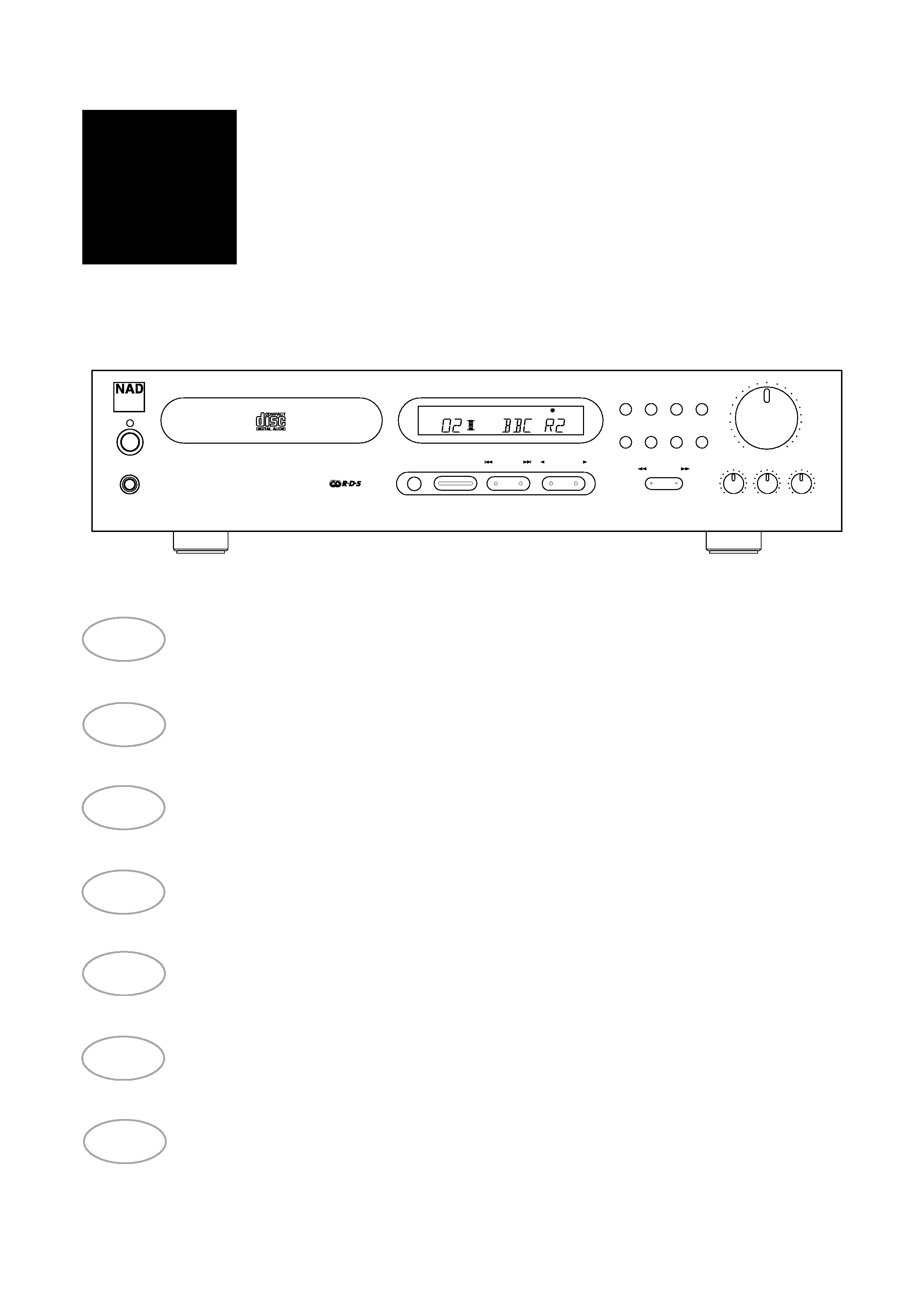
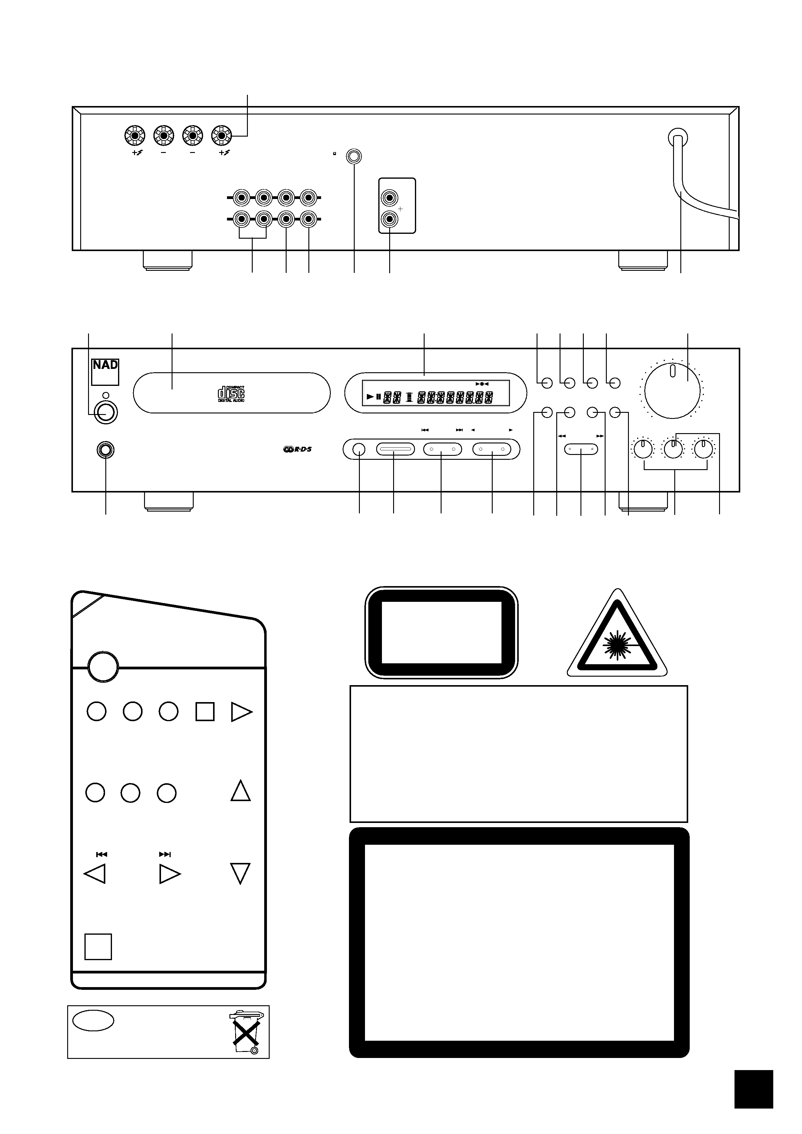
FRONT PANEL CONTROLS (Figure 2.)
NAD
L 40
CD
T
TAPE
MUTE
TUNER
STOP
PAUSE
PLAY
AUX
DISPLAY
DISPLAY
VOLUME
SKIP/PRESET
REMOTE CONTROL
NL
Batterij niet
weggooien maar
inleveren als KCA
WARNING - INVISIBLE LASER RADIATION WHEN OPEN AND
INTERLOCKS DEFEATED. AVOID EXPOSURE TO BEAM.
VORSICHT! - UNSICHTBARE LASERTRAHLUNG TRITT AUS,
WENN DECKEL GEÖFFNET UND WENN SICHERHEITSVERRIEGELUNG
ÜBERBRÜCKT IST. NICHT DEM STRAHL AUSSETZEN.
ADVARSEL - USYNLIG LASERSTRÅLING VED ÅBNING, NÅR
SIKKERHEDSAFBRYDERE ER UDE AF FUNKTION. UNDGÅ
UDSÆTTELSE FOR STRÅLING.
ADVARSEL - USYNLIG LASERSTRALING NÅR DEKSEL ÅPNES OG
SIKKERHEDSLÅS BRYTES. UNNGÅ EKSPONERING FOR STRÅLEN.
VARING - OSYNLING LASERSTRÅLNING NÄR DENNA DEL ÄR
ÖPPNAD OCH SPÄRRAR ÄR URKOPPLADE. STRÅLEN ÄR FARLIG.
VARO! - AVATTAESSA JA SUOJALUKITUS OHITETTAESSA OLET
ALTTINA NÄKTMÄTONTÄ LASERSÄTEILYLLE. ÄLÄ KAISO SÄTEESEEN.
CLASS 1 LASER PRODUCT
LUOKAN 1 LASERPLAITE
KLASS 1 LASERAPPARAT
REAR PANEL CONNECTIONS (Figure 1.)
OUT
IN
NAD
NAD LINK
IN
OUT
IN
TAPE
AUX
PRE
OUT
L
R
R
L
ANTENNA IN
FM 75
1
23
4
5
6
7
©1998.
NAD
ELECTRONICS
LTD.
L40
STORE
CANCEL
DISPLAY
MONO
BASS EQ
TONE
DEFEAT
RANDOM
REPEAT
VOLUME
TREBLE
BALANCE
BASS
INPUT SELECTOR
SEARCH / TUNE
PLAY
PAUSE
STOP OPEN
SKIP/ PRESET
Compact Disc Receiver L40
PHONES
2
5
6
7
8
1
1
3
4
9
11
13
15
20
18
19
10
12
17
14
16
RANDOM
REPEAT 1 ALL TOTAL
STEREO
RDS
kHz
MHz
PROGRAM
ANTENNA
REMAIN
BASS EQ
TONE DEFEAT
©1998.
NAD
ELECTRONICS
LTD.
L40
THIS DIGITAL APPARATUS DOES NOT EXCEED THE CLASS B
LIMITS FOR RADIO NOISE EMISSIONS FROM DIGITAL APPARA-
TUS AS SET OUT IN THE RADIO INTERFERENCE REGULATIONS
OF THE CANADIAN DEPARTMENT OF COMMUNICATIONS.
LE PRESENT APPAREIL NUMVERIQUE N'EMENT PAS DE
BRUITS RADIOELECTRIQUES DEPASSANT LES LIMITES
APPLICABLES AUX APPAREILS NUMERIQUES DE LA CALSSE B
PRESCRITES DANS LE REGLEMENT SUR LE BROUILLAGE
RADIO ELECTRIQUE EDICTE PAR LE MINISTERE DES COMMU-
NICATIONS DU CANADA.
SAFETY WARNING
NAD
4
connect the loudspeakers
Rear Panel connections
1
connect the FM antenna
Rear Panel connections
5
connect and use NAD-Link
Rear Panel connections
6
connect a tape recorder
Rear Panel connections
2
connect extra sound source
Rear Panel connections
3
(MiniDisc player, television) to AUX
switch Power on/off or to Stand-by/on
Front Panel Control
1
use the headphones socket
Front Panel Control
2
select a source
Front Panel Control
8
use the Tone controls & Tone Defeat
Front Panel Control
13 & 18
use Bass EQ
Front Panel Control
15
use the remote control
Remote control
replace remote control handset batteries
Remote control
Tuner: How to...
enter a preset
Front Panel Control
10
delete a preset
Front Panel Control
12
add/change a name to a preset
Front Panel Control
11
tune to a radio station automatically (search)
Front Panel Control
17
tune to a radio station manually
Front Panel Control
17
tune to a weak radio station (mute off)
Front Panel Control
16
display RDS information
Front Panel Control
14
(PS; station name and RT; RadioText)
CD: How to...
load a CD
Front Panel Control
3 & 5
play a CD
Front Panel Control
6
pause a CD
Front Panel Control
6
skip to a different track
Front Panel Control
7
engage Repeat 1 and Repeat All mode
Front Panel Control
9
program for selective track listening
Front Panel Control
10 & 12
engage Random Play
Front Panel Control
11
display time information of CD
Front Panel Control
14
scan within tracks
Front Panel Control
17
GB
INSTRUCTION MANUAL NAD L 40
CD RECEIVER.
General: How to...
Refer to: Chapter;
Section:
QUICK REFERENCE GUIDE:

NAD
5
GB
NOTES ON INSTALLATION
Your L 40 should be placed on a firm, level surface.
Avoid placing the unit in direct sunlight or near
sources of heat and damp.
Allow adequate ventilation. Do not place the unit on
a soft surface like a carpet. Do not put it in an
enclosed position such as a bookcase or cabinet that
may impede air-flow through the ventilation slots.
Switch the unit off before making any connections.
Use high quality RCA leads and connectors for
optimum performance and reliability. Ensure that
leads and connectors are not damaged in any way
and all connectors are firmly plugged. The RCA con-
nectors on your L 40 are colour coded red for Right
audio and white for Left audio.
For the best performance, use quality speaker
leads of 16 gauge thickness or more.
If the unit will not be used for some time, discon-
nect the plug from the AC socket.
Should water get into your L 40, shut off the power
to the unit and remove the plug from the AC socket.
Have the unit inspected by a qualified service techni-
cian before attempting to use it again.
Do not remove the cover, there are no user-ser-
viceable parts inside.
Use a dry soft cloth to clean the unit. If necessary,
lightly dampen the cloth with soapy water. Do not use
solutions containing benzol or other volatile agents.
REAR PANEL CONNECTIONS
1. SPEAKERS
Outputs for speakers with an impedance of 4 ohm
or more.
The 'RIGHT+' terminal should be connected to the
'+' terminal on your right-hand loudspeaker and the
'RIGHT-' connected to the loudspeaker's '-' terminal.
Connect to the left-hand speaker the terminals
marked 'LEFT+' and 'LEFT-' in the same way.
Heavy duty stranded wire or specialised speaker
cables to connect the loudspeakers to your L 40 is
recommended.
The high-current binding post terminals can be
used as a screw terminal for cables terminated within
spades or pin connectors, or for cables with bare wire
ends.
SPADE CONNECTORS
These should be slotted under the terminal's screw
bushings, which are then fully tightened. Ensure the
connectors are tightly secured and there is no danger
of bare metal from spade connectors touching the
back panel or another connectors, as this may cause
damage.
BARE WIRES AND PIN CONNECTORS
Bare wires and pin connectors should be inserted
into the hole in the shaft of the speaker terminals.
Unscrew the speaker terminal's plastic bushing until
the hole in the screw shaft is revealed. Insert the pin
or bare cable end into the hole and secure by tighten-
ing down the terminal's bushing.
Avoid any bare metal from speaker cables touching
the back panel or another connector. Ensure that
there is only 1/2" (1cm) of bare cable or pin and no
loose strands of speaker wire.
2. TAPE IN, OUT
Connections for analogue recording and playback
to an audio tape recorder of any type. Using a twin
RCA-to-RCA lead, connect the left and right output
(often labelled as "playback", "Line out", "Output",
"Analogue Output") of the tape machine to the TAPE
IN connectors of the L 40 for playback. Connect the
left and right input (often labelled as "Record", "Line
in", "Input", "Analogue Input") of the tape machine to
the TAPE OUT connectors of the L 40 for recording.
3. AUX INPUT
Input for additional line level input signals such as a
minidisc player. Use a twin RCA-to-RCA lead to con-
nect the auxiliary unit's left and right line level out-
puts (often labelled as "Line out", "Output", "Analogue
output") to this input.
4. PRE OUT
Connections to an external power amplifier.
5. FM ANTENNA
A ribbon wire FM antenna is included and should
be connected to the FM ANTENNA connector at the
rear of the unit using the 'balun' adapter supplied.
The ribbon aerial should be mounted on a vertical
surface and placed so that it forms a 'T'.
Experiment with placement of the antenna to find
the position that gives the best signal strength and
lowest background noise.
An inadequate FM signal normally results in high
level of hiss, especially with stereo reception, and
interference from external electrical sources. The per-
formance of tuner section can be improved by using
an externally mounted FM antenna. A qualified aerial
installer will be able to advise and fit a recommended
aerial for your reception conditions.
6. NAD-LINK IN, OUT
The NAD-Link connectors are used to pass com-
mands from the remote control to and from other
units fitted with NAD-Link connectors. This allows
centralised control of a complete system or gives sys-
tem control from more than one room and remote
control operation of NAD units that are not remote
controllable on their own.