
·
Top View..................................................4-1
·
Top View(without Tray Disc) .................4-1
·
Bottom View ...........................................4-1
1. Holder Clamp....................................4-2
1-1. Clamp Assembly Disc .......................4-2
1-1-1. Plate Clamp ..................................4-2
1-1-2. Magnet Clamp ..............................4-2
1-1-3. Clamp Upper.................................4-2
2. Tray Disc ...........................................4-2
3. Base Assembly Sled ........................4-3
3-1. Gear Assembly Feed ........................4-3
3-2. Gear Assembly Middle......................4-3
3-3. Gear Assembly Rack ........................4-3
4. Rubber Rear......................................4-3
5. Frame Assembly Up/Down ..............4-4
6. Belt Loading......................................4-4
7. Gear Pulley .......................................4-4
8. Gear Loading ....................................4-4
9. Guide Up/Down.................................4-4
10. PWB Assembly Loading ................4-4
11. Base Main........................................4-4
1. Tools and Fixtures for SVC .............4-5
2. Install Process ..................................4-5
3. Adjustment Process.........................4-6
1. Deck Mechanism Exploded View....4-7
CONTENTS
SECTION 4 MECHANISM
DECK MECHANISM PARTS
LOCATIONS
EXPLODED VIEW
DECK MECHANISM ADJUSTMENT
DECK MECHANISM
DISASSEMBLY
4-1
DECK MECHANISM PARTS LOCATION
Starting No.
1
1, 2
1, 2, 3
1, 2, 3, 4
1
1, 6
1, 2, 6
1, 2, 6, 8
1, 2, 6, 8,
9
1, 2, 7
1, 2, 7
1, 2
1, 2 ,13
1, 2, 13, 14
1, 2, 7, 12, 13, 14
1, 2, 13
1, 2, 7, 12, 13,
14, 15, 16, 17
1
2
3
4
5
6
7
8
9
10
11
12
13
14
15
16
17
18
Holder
Clamp
Clamp Assembly
Disc
Plate Clamp
Magnet Clamp
Clamp Upper
Tray Disc
Base Assembly Sled
Gear Assembly
Feed
Gear
Middle
Gear Assembly
Rack
Rubber Rear
Frame Assembly
Up/Down
Belt Loading
Gear Pulley
Gear Loading
Guide Up/Down
PWB Assembly
Loading
Base Main
2 Screws,
2 Locking Tabs
4 Screws,
1 Connector
1 Locking Tabs
1 Screw
1 Screw
1 Locking Tab
1 Locking Tab
1 Locking Tab
1 Hook
2Screw
2 Locking Tabs
4-1
4-1
4-1
4-1
4-1
4-2
4-3
4-3
4-3
4-3
4-3
4-4
4-4
4-4
4-4
4-4
4-4
4-4
Bottom
Bottom
Procedure
Parts
Fixing Type
Fig-
ure
Disass
embly
Note
When reassembling, perform the procedure in
reverse order.
The "Bottom" on Disassembly column of above
Table indicates the part should be disassembled
at the Bottom side.
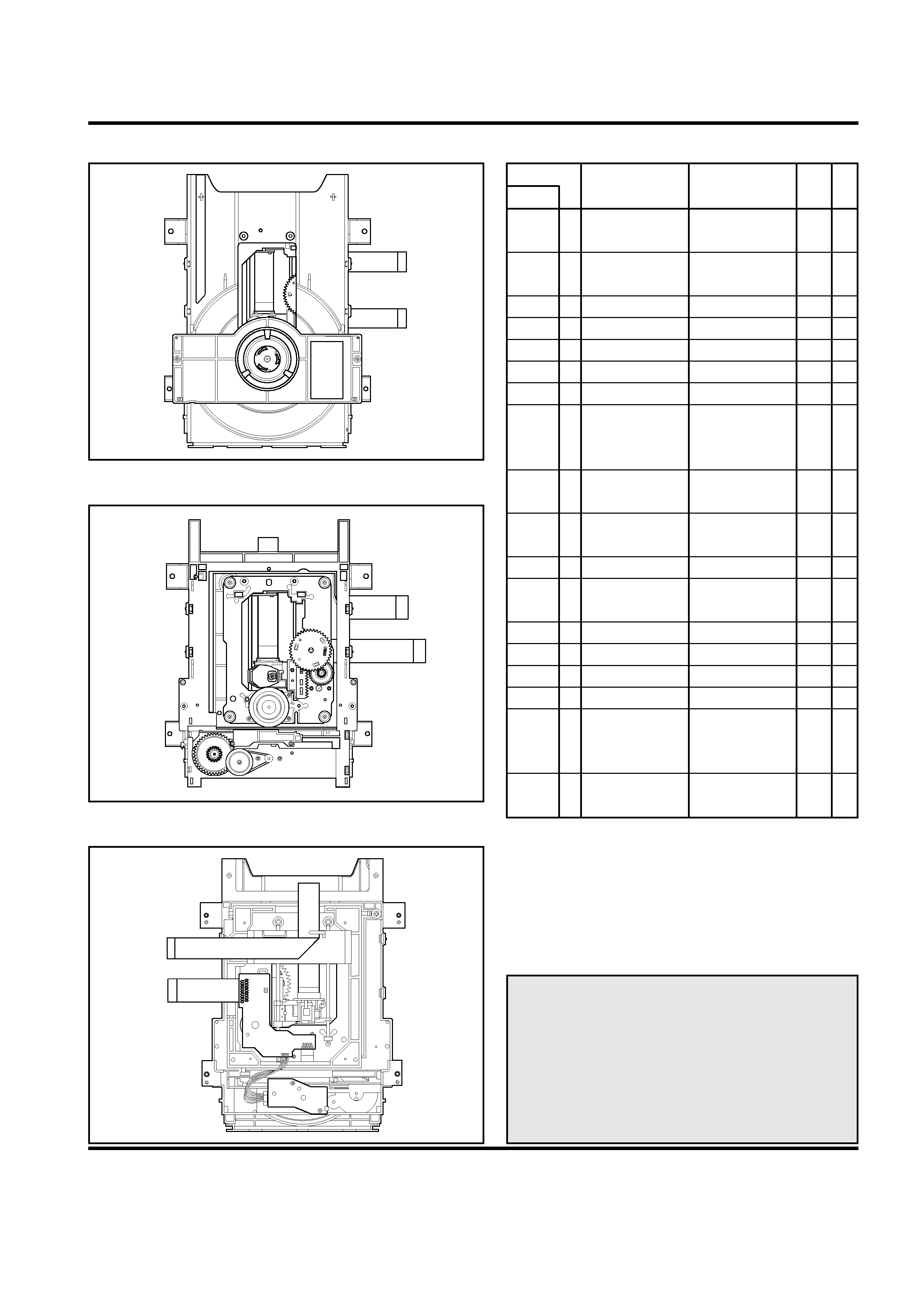
· Top View (Without Tray)
· Bottom View
· Top View (With Tray)
4-2
DECK MECHANISM DISASSEMBLY
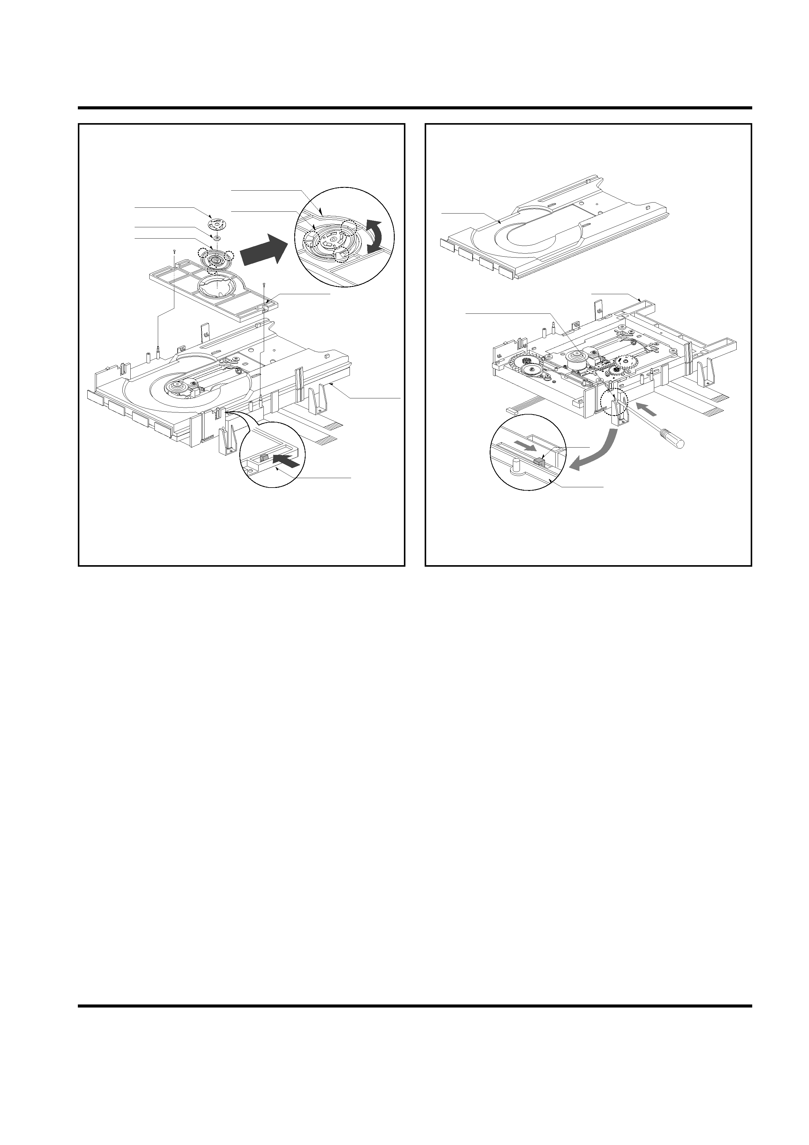
1. Holder Clamp (Fig. 4-1)
1) Release 2 Screws(S1).
2) Unhook 2 Locking Tabs(L1).
3) Lift up the Holder Clamp and then separate it from the
Base Main.
1-1. Clamp Assembly Disc
1) Place the Clamp Assembly Disc as Fig. (A)
2) Lift up the Clamp Assembly Disc in direction of
arrow(A).
3) Separate the Clamp Assembly Disc from the Holder
Clamp.
1-1-1. Plate Clamp
1) Turn the Plate Clamp to counterclockwise direction and
then lift up the Plate Clamp.
1-1-2. Magnet Clamp
1-1-3. Clamp Upper
2. Tray Disc (Fig. 4-2)
1) Insert and push a Driver in the emergency eject
hole(A) at the right side, or put the Driver on the
Lever(B) of the Gear Emergency and pull the Lever(B)
in direction of arrow so that the Tray Disc is ejected
about 15~20mm.
2) Pull the Tray Disc until it is separated from the Base
Main completely.
BASE MAIN
HOLDER CLAMP
HOLDER CLAMP
CLAMP ASSEMBLY DISC
HOLDER CLAMP
PLATE CLAMP
(S1)
(S1)
(A)
(L1)
(L1)
(Fig. A)
MAGNET CLAMP
CLAMP UPPER
(B)
LEVER
BOTTOM SIDE VIEW
EMERGENCY EJECT HOLE
(A)
TRAY DISC
BASE MAIN
BASE MAIN
Fig. 4-1
Fig. 4-2
4-3
DECK MECHANISM DISASSEMBLY
(C1)
PICK UP
ASSEMBLY
GENERAL
GEAR ASSEMBLY FEED
GEAR MIDDLE
GAER ASSEMBLY RACK
MOTOR ASSEMBLY SPINDLE
(L2)
(S2)
(S2)
(S2)
(S3)
GEAR ASSEMBLY RACK
GEAR MIDDLE
GEAR ASSEMBLY FEED
BASE PU(OUTSERT)
PICK UP ASSEMBLY GENERAL
MOTOR ASSEMBLY SPINDLE
RUBBER REAR
(S2)
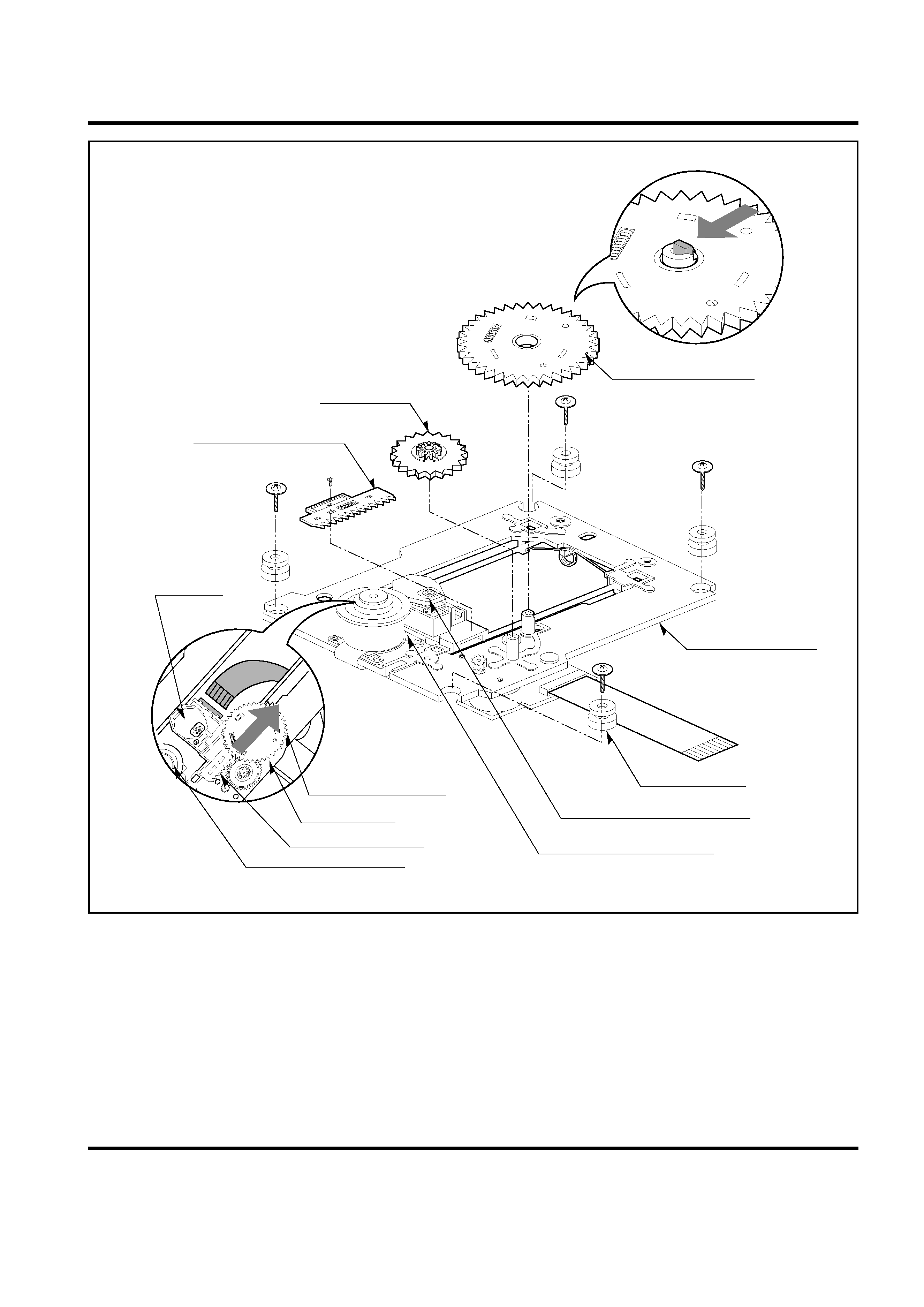
3. Base Assembly Sled (Fig. 4-3)
1) Release 4 Screw(S2).
2) Disconnect the FFC Connector(C1)
3-1. Gear Assembly Feed
1) Unhook the Locking Tab(L2) in direction of arrow.
3-2. Gear Middle
3-3. Gear Assembly Rack
1) Release the Scerw(S3)
4. Rubber Rear (Fig. 4-3)
Fig. 4-3
4-4
DECK MECHANISM DISASSEMBLY
(B)
(S5)
(L6)
(L4)
(L5)
(A)
(L3)
(A)
(L6)
(H1)
(L6)
FIG. (B)
GUIDE UP/DOWN
BASE MAIN
BASE MAIN
PWB ASSEMBLY LOADING
GEAR LOADING
BELT LOADING
FRAME ASSEMBLY UP/DOWN
GUIDE UP/DOWN
GUIDE UP/DOWN
GUIDE UP/DOWN
(A)
(B)
(S4)
FIG. (C)
FIG. (A)
(B)
(C)
GEAR PULLEY
Fig. 4-4
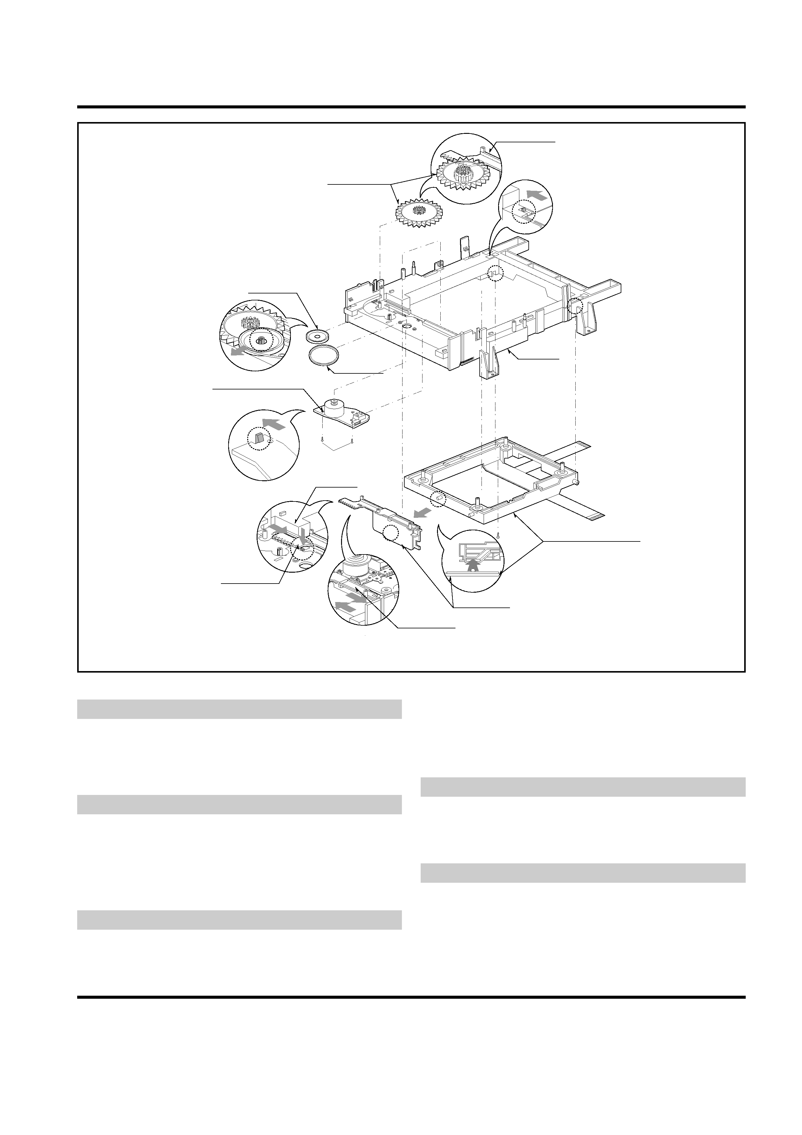
5. Frame Assembly Up/Down
Put the Base Main face down(Bottom Side)
1) Release the Screw(S4)
2) Unlock the Locking Tab(L3) in direction of arrow and
then lift up the Frame Assembly Up/Down to separate
it from the Base Main.
· When reassembling move the Guide Up/Down in direction
of arrow(C) until it is positioned as Fig.(C).
· When reassembling insert (A) portion of the Frame
Assembly Up/Down in the (B) portion of the Guide
Up/Down as Fig.(B)
6. Belt Loading(Fig. 4-4)
Put the Base Assembly Main on original position(Top Side)
7. Gear pulley (Fig. 4-4)
1) Unlock the Locking Tab(L4) in direction of arrow(B) and
then separate the Gear Pulley from the Base Main.
8. Gear Loading (Fig. 4-4)
9. Guide Up/Down (Fig. 4-4)
1) Move the Guide Up/Down in direction of arrow(A) as
Fig.(A)
2) Push the Locking Tab(L5) down and then lift up the
Guide Up/Down to separate it from the Base Main.
When reassembling place the Guide Up/Down as Fig.(C)
and move it in direction arrow(B) until it is locked by the
Locking Tab(L5). And confirm the Guide Up/Down as Fig.(A)
10. PWB Assembly Loading
Put the Base Main face down(Bottom Side)
1) Release 2 Screws(S5)
2) Unkool the Loading Motor Connector (C2) from the
Hook (H1) on the Base Main.
3) Unlock 2 Locking Tabs(L6) and separate the PWB
Assembly Loading from the Base Main.
11. Base Main(Fig. 4-4)
Note
Note
Note
Note
Note