C440
Stereo AM/FM Tuner
Owner's Manual
GB
Manuel d'Installation
F
Bedienungsanleitung
D
Manual del Usuario
E
Manuale delle Istruzioni
I
Manual do Proprietário
P
Bruksanvisning
S
Warning: To reduce the risk of fire or electric shock, do not
expose this unit to rain or moisture.
The lightning flash with an arrowhead symbol within an equilateral
triangle, is intended to alert the user to the presence of uninsulated
"dangerous voltage" within the product's enclosure that may be of
sufficient magnitude to constitute a risk of electric shock to persons.
The exclamation point within an equilateral triangle is intended to
alert the user to the presence of important operating and
maintenance (servicing) instructions in the literature accompanying
the product.
Do not place this unit on an unstable cart, stand or tripod, bracket
or table. The unit may fall, causing serious injury to a child or adult
and serious damage to the unit. Use only with a cart, stand, tripod,
bracket or table recommended by the manufacturer or sold with
the unit. Any mounting of the device on a wall or ceiling should
follow the manufacturer's instructions and should use a mounting
accessory recommended by the manufacturer.
An appliance and cart combination should be moved with care.
Quick stops, excessive force and uneven surfaces may cause the
appliance and cart combination to overturn.
Read and follow all the safety and operating instructions before
connecting or using this unit. Retain this notice and the owner's
manual for future reference.
All warnings on the unit and in its operating instructions should be
adhered to.
Do not use this unit near water; for example, near a bath tub,
washbowl, kitchen sink, laundry tub, in a wet basement or near a
swimming pool.
The unit should be installed so that its location or position does not
interfere with its proper ventilation. For example, it should not be
situated on a bed, sofa, rug or similar surface that may block the
ventilation openings; or placed in a built-in installation, such as a
bookcase or cabinet, that may impede the flow of air through its
ventilation openings.
The unit should be situated from heat sources such as radiators,
heat registers, stoves or other devices (including amplifiers) that
produce heat.
The unit should be connected to a power supply outlet only of the
voltage and frequency marked on its rear panel.
The power supply cord should be routed so that it is not likely to be
walked on or pinched, especially near the plug, convenience
receptacles, or where the cord exits from the unit.
Unplug the unit from the wall outlet before cleaning. Never use
benzine, thinner or other solvents for cleaning. Use only a soft
damp cloth.
The power supply cord of the unit should be unplugged from the
wall outlet when it is to be unused for a long period of time.
Care should be taken so that objects do not fall, and liquids are not
spilled into the enclosure through any openings.
This unit should be serviced by qualified service personnel when:
A. The power cord or the plug has been damaged; or
B. Objects have fallen, or liquid has been spilled into the unit; or
C. The unit has been exposed to rain or liquids of any kind; or
D. The unit does not appear to operate normally or exhibits a
marked change in performance; or
E. The device has been dropped or the enclosure damaged.
DO NOT ATTEMPT SERVICING OF THIS UNIT
YOURSELF. REFER SERVICING TO QUALIFIED
SERVICE PERSONNEL
Upon completion of any servicing or repairs, request the service
shop's assurance that only Factory Authorized Replacement Parts
with the same characteristics as the original parts have been used,
and that the routine safety checks have been performed to
guarantee that the equipment is in safe operating condition.
REPLACEMENT WITH UNAUTHORIZED PARTS MAY RESULT IN FIRE,
ELECTRIC SHOCK OR OTHER HAZARDS.
ATTENTION
POUR ÉVITER LES CHOC ELECTRIQUES, INTRODUIRE LA
LAME LA PLUS LARGE DE LA FICHE DANS LA BORNE
CORRESPONDANTE DE LA PRISE ET POUSSER JUSQU'AU
FOND.
CAUTION
TO PREVENT ELECTRIC SHOCK, MATCH WIDE BLADE OF
PLUG TO WIDE SLOT FULLY INSERT.
If an indoor antenna is used (either built into the set or installed
separately), never allow any part of the antenna to touch the metal
parts of other electrical appliances such as a lamp, TV set etc.
CAUTION
POWER LINES
Any outdoor antenna must be located away from all power lines.
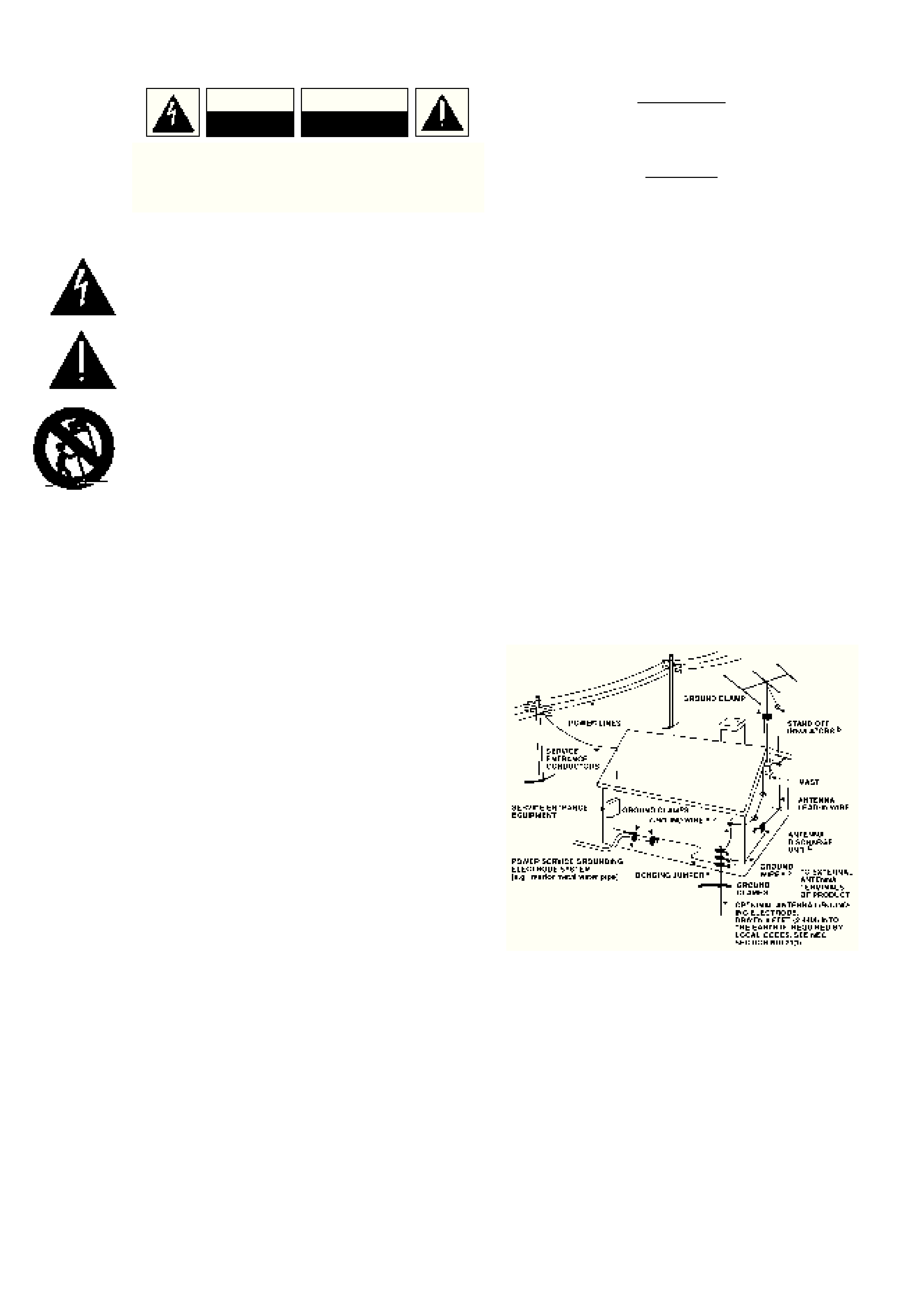
OUTDOOR ANTENNA GROUNDING
If an outside antenna is connected to your tuner or tuner-
preamplifier, be sure the antenna system is grounded so as to
provide some protection against voltage surges and built-up static
charges. Article 810 of the National Electrical Code, ANSI/NFPA No.
70-1984, provides information with respect to proper grounding of
the mast and supporting structure, grounding of the lead-in wire to
an antenna discharge unit, size of grounding conductors, location of
antenna discharge unit, connection to grounding electrodes and
requirements for the grounding electrode.
a. Use No. 10 AWG (5.3mm2) copper, No. 8 AWG (8.4mm2)
aluminium, No. 17 AWG (1.0mm2) copper-clad steel or bronze
wire, or larger, as a ground wire.
b. Secure antenna lead-in and ground wires to house with stand-off
insulators spaced from 4-6 feet (1.22 - 1.83 m) apart.
c. Mount antenna discharge unit as close as possible to where lead-
in enters house.
d. Use jumper wire not smaller than No.6 AWG (13.3mm2) copper,
or the equivalent, when a separate antenna-grounding electrode
is used. see NEC Section 810-21 (j).
EXAMPLE OF ANTENNA GROUNDING AS PER NATIONAL ELECTRICAL
CODE INSTRUCTIONS CONTAINED IN ARTICLE 810 - RADIO AND
TELEVISION EQUIPMENT.
NOTE TO CATV SYSTEM INSTALLER: This reminder is
provided to call the CATV system installer's attention to
Article 820-40 of the National Electrical Code that provides
guidelines for proper grounding and, in particular, specifies
that the ground cable ground shall be connected to the
grounding system of the building, as close to the point of
cable entry as practical.
CAUTION
RISK OF ELECTRIC
SHOCK DO NOT OPEN
ATTENTION:
RISQUE DE CHOC ELECTRIQUE
NE PAS OUVRIR
CAUTION: TO REDUCE THE RISK OF ELECTRIC
SHOCK, DO NOT REMOVE COVER (OR BACK). NO
USER SERVICEABLE PARTS INSIDE. REFER SERVICING
TO QUALIFIED SERVICE PERSONNEL.
IMPORTANT SAFETY INSTRUCTIONS
2
3
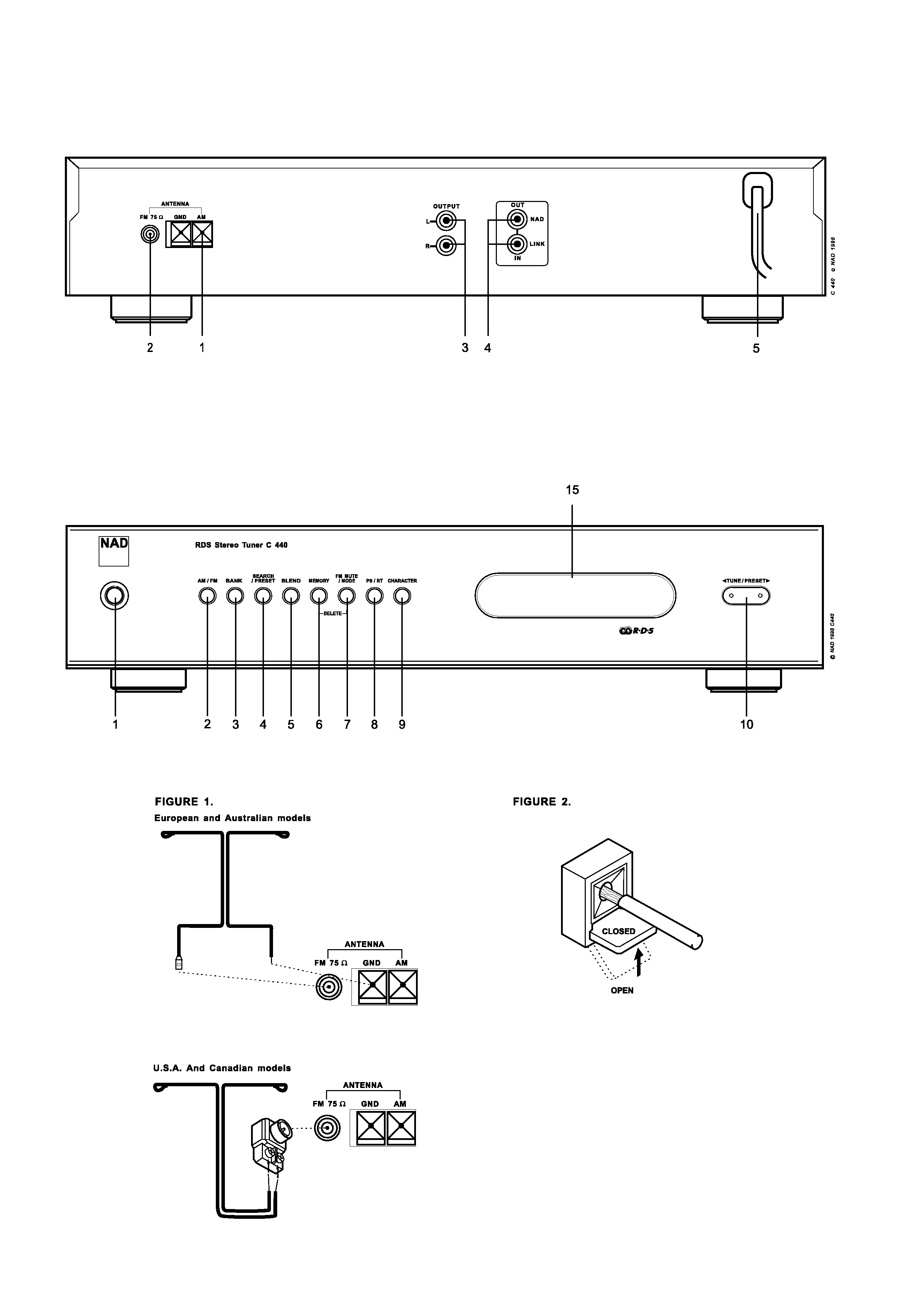
REAR PANEL CONNECTIONS
FRONT PANEL CONTROLS

NOTES ON INSTALLATION
Your NAD C440 should be placed on a firm, level surface. Avoid
placing the unit in direct sunlight, near sources of heat and damp
or in poorly ventilated positions.
It comes with RCA leads for connection to your amplifier. Ensure
that leads and connectors are not damaged in any way and all
connectors are firmly pushed home.
If the unit is not going to be used for some time, disconnect the
plug from the AC socket.
Should water get into your NAD C440, shut off the power to the
unit and remove the plug from the AC socket. Have the unit
inspected by a qualified service technician before attempting to
use it again. Do not remove the cover, there are no user-
serviceable parts inside.
Use a dry soft cloth to clean the unit. If necessary, lightly dampen
the cloth with soapy water. Do not use solutions containing benzol
or other volatile agents.
QUICK START
Use the RCA-to-RCA lead to connect the NAD C440 left & right
outputs to the Tuner Input of your amplifier.
1. Plug in the AC power cord.
2. Connect AM and FM antenna.
3. Connect C440 outputs to amplifier.
4. Press the POWER button (No. 1) to turn on the NAD C440.
5. Press the AM/FM button (No. 2) to select AM or FM reception.
6. Press Search/Preset until "SEARCH" is indicated in the display
to select Search mode.
7. Use TUNE/PRESET to select a station.
REAR PANEL CONNECTIONS
1. AM ANTENNA
An AM loop antenna is supplied with the NAD C440 and is
required for AM reception. To connect the AM antenna, first press
the keys on the Antenna terminals downwards. Insert the bare
antenna wires into the two terminal holes and push the connector
keys upwards again to secure the connection (see fig 2).
Test various positions for the antenna but always ensure the loop
is placed vertically for best reception. Placing the antenna close to
large metal items such as metal shelves or radiators may interfere
with reception.
2. FM ANTENNA
A ribbon wire FM antenna is included and should be connected to
the FM connector at the rear of the unit (120V versions (North
America) should use the `balun' adapter supplied - see fig 1). The
ribbon aerial should be mounted on a vertical surface and placed
so that it forms a `T'.
Experiment with placement of the antenna to find the position that
gives the best signal strength and lowest background noise. An
inadequate FM signal normally results in high levels of hiss,
especially in stereo, and interference from external electrical
sources. In areas of poor FM reception, the tuner section's
performance can be improved by using an externally mounted FM
antenna. A qualified aerial installer will be able to advise and fit a
recommended aerial for your reception conditions.
3. OUTPUT
Using twin RCA-to-RCA leads, connect to the left (white) and right
(red) audio outputs to the `Tuner' input or other line-level input
such as `Aux' input of your amplifier.
4. NAD-LINK IN OUT
The NAD-Link connector is used to pass commands from other
units fitted with NAD-Link connectors. This allows centralised
control of a complete system, and also allows some of the basic
functions of the NAD C440 to be controlled using a NAD-linked
amplifier's remote control or gives system control from more than
one room. To function with such other units, connect the Tuner's
NAD-Link IN to the NAD-Link Out on the other unit. NAD-Link
connectors can be daisy-chained, IN to OUT, so that a whole system
can be controlled from the remote control facilities of one unit.
5. AC LINE CORD
Plug the AC power cord into a live AC wall socket or to an AC
convenience outlet at the rear of your amplifier.
FRONT PANEL CONTROLS
1. POWER ON/OFF
POWER switches the tuner on or off. Pressing the power switch
turns the Tuner on, indicated by the Display Panel becoming
active. Pressing the POWER button again will switch the unit off.
The C440 uses a memory back-up system to store Preset
information. This information is retained for several weeks, even
if the unit is switched off completely or unplugged.
NOTE: When switching power On, the C440 will go back to the
station last tuned to before the unit was turned off. This will allow
you to make timer recordings using an external timer and
recorder.
2. AM/FM
The AM/FM button switches the tuner from the AM band to the FM
band and vice-versa. The Display Panel shows the frequency of the
tuned station and which band is selected. The FM tuning is in
0.025 MHz increments, AM tuning is in 9 kHz or 10 kHz
increments, depending on the version.
3. BANK
Pressing Bank switches between the C440's three Preset Memory
Banks (A, B or C). Each of these banks can hold up to 10 Preset
stations. These Banks can contain a mix of AM or FM stations
each. The Bank selected is shown in the Display Panel. You can
use the banks to sort your Presets, for instance by station type
(Bank A for rock/pop; Bank B for Classical music; Bank C for
Jazz). Refer to the separate chapter "Storing, recalling and naming
Presets" for more information.
GB
4
NAD C440 Stereo AM/FM Tuner

4. SEARCH/PRESET
The Search/Preset button scrolls between three different tuning
modes, each successive push of the button engages the next one
of the three modes.
a) Preset mode: In this mode you can use the Tune/Preset button
(No. 10) to select a Preset. When Preset Mode is selected
"PRESET" lights up in the display.
b) Search mode: By pressing the Tune/Preset button (10)
or
you can engage automatic tuning respectively up or down
the frequency band . The tuner will search automatically for
the first reasonably strong radio station, where it will stop.
Press the Tune/Preset button again to start searching again.
"SEARCH" lights up in the display. If a stereo station is received
"STEREO" will light up in red in the display, unless FM
Mute/Mode (No. 7) was engaged.
c) Tune mode: By pressing the Tune/Preset button (No. 10)
or
you can engage manual tuning respectively up or down
the frequency band for precise tuning to a specific frequency.
Keep either one of the Tune/Preset buttons pressed until you
are in the proximity of the desired frequency (use the
to
tune upwards in frequency;
for downwards tuning). With
each successive tap of the keys, the tuner will take 0.025MHz
steps on FM so you can accurately tune into the desired
frequency. For AM the tuning steps can be 9 kHz or 10 kHz,
depending on the version of your C440. This tuning mode can
also be useful when trying to receive a radio station which is
too weak for the Search mode. When tuned accurately to a
station, ">TUNED<" will light up in the display.
NOTE: The Search/Preset buttons are also used in conjunction
with the Memory (No. 6) and Tune/Search (No. 10) buttons to
add and memorise user defined names to Presets. Refer to the
separate chapter "Storing, recalling and naming Presets" for more
information.
5. BLEND
Weak or remote stereo radio stations are sometimes received with
noise and hiss as the antenna signal is too weak. By switching the
tuner to mono will reduce the amount of noise and hiss but at the
expense of any stereo information. The NAD Blend feature will
allow you to reduce the amount noise and hiss but still retain
some level of stereo separation, instead of mono.
The Blend button toggles between engaging or disengaging the
Blend feature; when engaged, "BLEND" lights up in the display.
6. MEMORY
The Memory is used to store stations into the three Preset Memory
banks or to store user defined names for non-RDS Preset stations.
Used in conjunction with the Search/Preset (No.4) and
Tune/Preset (No. 10) buttons. When Memory is active, the Preset
number flashes and the red `MEMORY' indicator is shown in the
Display Panel. Refer to the separate chapter "Storing, recalling
and naming Presets" for more information.
Note: The 120V versions (North America) do not have RDS
(Radio Data System).
7. FM MUTE/MODE
This button combines two functions; it switches the tuner from
Stereo to Mono and disengages the muting circuitry at the same
time. The muting circuit will mute the tuner in between radio
stations when searching or tuning. This way the tuning noise is
avoided.
Very weak radio station signals however may be suppressed by the
muting circuit. if such a very weak station is in stereo it will have
a high level of background hiss. Switching to Mono Mode and
disengaging the muting circuit by depressing the FM MUTE/MODE
button will allow the station to be heard and will cancel most or
all of this background noise.
In normal operation the mute circuit is engaged, the display
indicates "FM MUTE". Press the FM Mute/Mode button to
disengage the muting circuit and switch from stereo to mono
reception. "FM MUTE" in the display will extinguish. Press the FM
Mute/Mode switch again to return to Auto Stereo FM operation.
8. PS/RT (ON RDS VERSIONS ONLY)
With stations carrying RDS information, The PS/RT button scrolls
between three different display modes, each successive push of
the button engages the next one of the three modes:
a) In the default mode, the station's RDS name is displayed,
Program Service (PS; normally the station's calling letters, BBC
R3, for instance).
b) From the default mode, press the button once to view Radio
Text (RT). This can be additional information such as the
presenter's or program's name; what song is playing, etc. This
text scrolls continuously over the 8 alphanumeric display
segments. It takes a few seconds for the tuner to gather the RT
information, so immediately after tuning to a station and
selecting to view RT the display will indicate "WAIT" and
default to the station name.
c) Press the button from the display RT mode to display the
station frequency. Press again to return to the default mode
(a).
When tuned to a non-RDS station
The Display button toggles the display to show either the station
frequency or user entered station name. If no user name was
entered the display will just flash once.
NOTE: The 120V versions (North America) do not have RDS
(Radio Data System)
8. DISPLAY (ON NON-RDS VERSIONS ONLY)
The Display button toggles the display to show either the station
frequency or user entered station name. If no user name was
entered the display will just flash once.
9. CHARACTER
The Character Button is used to enter the names of Preset radio
stations for display when the station is selected. Used together with
the Tune/Preset (No. 10) and MEMORY (No. 6) Buttons. Refer to
the separate chapter "Storing, recalling and naming Presets" for
more information.
GB
5