NAD
710
· OWNER'S MANUAL
· MANUEL D'INSTALLATION
· BEDIENUNGSANLEITUNG
· MANUAL DEL USUARIO
· MANUALE DELLE ISTRUZIONI
· BRUKSANVISNING
· MANUAL DO PROPRIETÁRIO
GB
F
D
E
I
S
P
©
1996.
710.
NAD
ELECTRONICS
LTD
Warning: To reduce the risk of fire or electric shock, do not expose
this unit to rain or moisture.
The lightning flash with an arrowhead symbol within an equilateral
triangle is intended to alert the user to the presence of uninsu-
lated "dangerous voltage" within the product's enclosure that
may be of sufficient magnitude to constitutet a risk of electric
shock to persons.
The exclamation point within an equilateral triangle is intended to
alert the user to the presence of important operating and main-
tenance (servicing) instructions in the literature accompany-
ing the product.
Do not place this unit on an unstable cart, stand or tri-
pod, bracket or table. The unit may fall, causing seri-
ous injury to a child or adult and serious damage to the
unit. Use only with a cart, stand, tripod, bracket or
table recommended by the manufacturer or sold with
the unit. Any mounting of the device on a wall or ceil-
ing should follow the maufacturer's instructions and
should use a mounting accessory recommended
by the manufacturer.
An appliance and cart combination should be moved with care. Quick
stops, excessive force and uneven surfaces may cause the appliance
and cart combination to overturn.
Read and follow all the safety and operating instructions before connect-
ing or using this unit. Retain this notice and the owner's manual for future
reference.
All warnings on the unit and in it's operating instructions should be
adhered to.
Do not use this unit near water; for example, near a bath tub, washbowl,
kitchen sink, laundry tub, in a wet basement or near a swimming pool.
The unit should be installed so that its location or position does not inter-
fere with its proper ventilation. For example, it should not be situated on
a bed, sofa, rug or similar surface that may block the ventilation open-
ings; or placed in a built-in installation, such as a bookcase or cabinet,
that may impede the flow of air through its ventilation openings.
The unit should be situated from heat sources such as radiators, heat
registers, stoves or other devices (including amplifiers) that produce heat.
The unit should be connected to a power supply outlet only of the voltage
and frequency marked on its rear panel.
The power supply cord should be routed so that it is not likely to be
walked on or pinched, especially near the plug, convenience receptacles,
or where the cord exits from the unit.
Unplug the unit from the wall outlet before cleaning. Never use benzine,
thinner or other solvents for cleaning. Use only a soft damp cloth.
The power supply cord of the unit should be unplugged from the wall out-
let when it is to be unused for a long period of time.
Care should be taken so that objects do not fall, and liquids are not
spilled into the enclosure through any openings.
This unit should be serviced by qualified service personnel when:
A. The power cord or the plug has been damaged; or
B. Objects have fallen, or liquid has been spilled into the unit; or
C. The unit has been exposed to rain or liquids of any kind; or
D. The unit does not appear to operate normally or exhibits a marked
change in performance; or
E. The device has been dropped or the enclosure damaged.
Upon completion of any servicing or repairs, request the service shop's
assurance that only Factory Authorized Replacement Parts with the
same characteristics as the original parts have been used, and that the
routine safety checks have been performed to guarantee that the equip-
ment is in safe operating condition.
REPLACEMENT WITH UNAUTHORIZED PARTS MAY RESULT IN
FIRE, ELECTRIC SHOCK OR OTHER HAZARDS.
ATTENTION
POUR EVITER LES CHOC ELECTRIQUES, INTRODUIRE LA
LAME LA PLUS LARGE DE LA FICHE DANS LA BORNE
CORRESPONDANTE DE LA PRISE ET POUSSER JUSQU'AU
FOND.
CAUTION
TO PREVENT ELECTRIC SHOCK MATCH WIDE BLADE OF
PLUG TO WIDE SLOT FULLY INSERT.
If an indoor antenna is used (either built into the set or installed separate-
ly), never allow any part of the antenna to touch the metal parts of other
electrical appliances such as a lamp, TV set etc.
CAUTION
POWER LINES
Any outdoor antenna must be located away from all power lines.
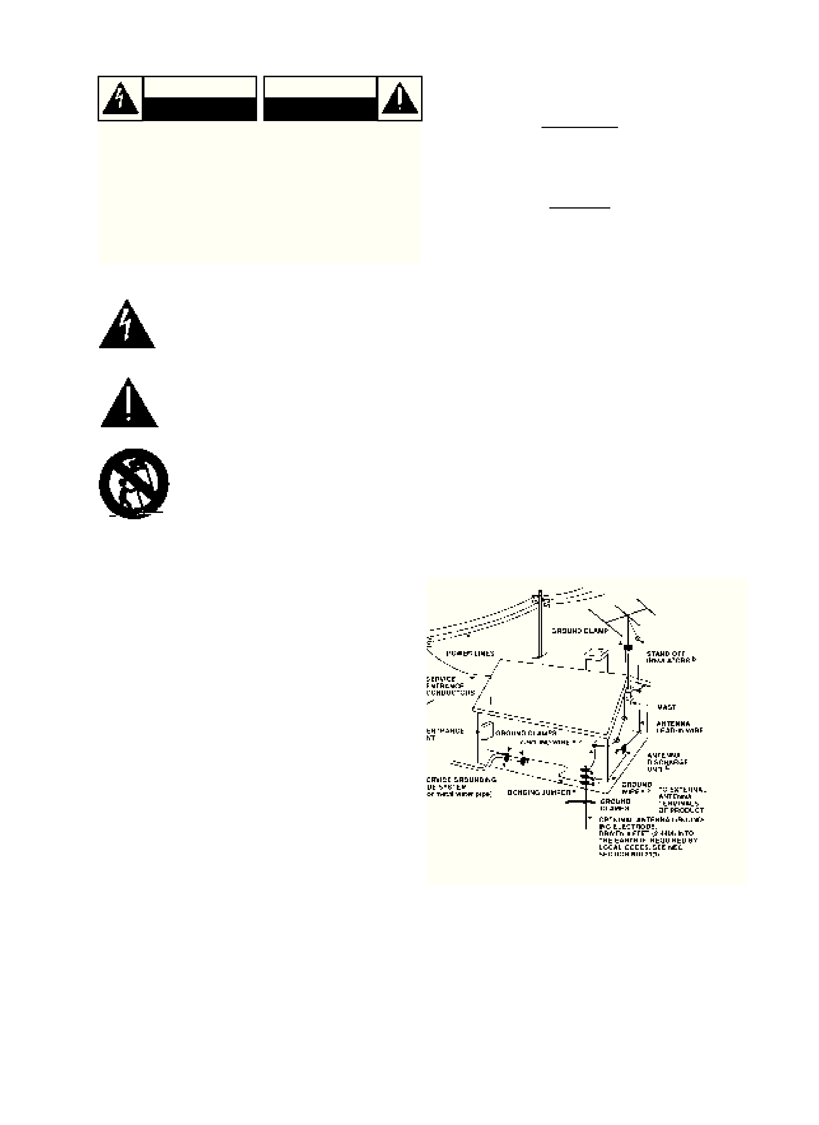
OUTDOOR ANTENNA GROUNDING
If an outside antenna is connected to your tuner or tuner-preamplifier, be
sure the antenna system is grounded so as to provide some protection
against voltage surges and built-up static charges. Section 810 of the
National Electrical Code, ANSI/NFPA No. 70-1984, provides information
with respect to proper grounding of the mast and supporting structure,
grounding of the lead-in wire to an antenna discharge unit, size of
grounding conductors, location of antenna discharge unit, connection to
grounding electrodes and requirements for the grounding electrode.
a. Use No. 10 AWG (5.3mm2) copper, No. 8 AWG (8.4mm2) aluminium,
No. 17 AWG (1.0mm2) copper-clad steel or bronze wire, or larger, as a
ground wire.
b. Secure antenna lead-in and ground wires to house with stand-off insu-
lators spaced from 4-6 feet (1.22 - 1.83 m) apart.
c. Mount antenna discharge unit as close as possible to where lead-in
enters house.
d. Use jumper wire not smaller than No.6 AWG (13.3mm2) copper, or the
equivalent, when a separate antenna-grounding electrode is used. see
NEC Section 810-21 (j).
EXAMPLE OF ANTENNA GROUNDING AS PER NATIONAL ELECTRI-
CAL CODE INSTRUCTIONS CONTAINED IN ARTICLE 810 - RADIO
AND TELEVISION EQUIPMENT.
NOTE TO CATV SYSTEM INSTALLER: This reminder is pro-
vided to call the CATV system installer's attention to Article 820-
22 of the National Electrical Code that provides guidelines for
proper grounding and, in particular, specifies that the ground
cable ground shall be connected to the grounding system of the
building, as close to the point of cable entry as practical.
CAUTION: TO REDUCE THE RISK OF ELECTRIC
SHOCK, DO NOT REMOVE COVER (OR BACK)
NO USER SERVICEABLE PARTS INSIDE. REFER SER-
VICING TO QUALIFIED SERVICE PERSONNEL.
ATTENTION: AFIN DEVITER UN CHOC ELECTRIQUE,
ET LES CONSEQUENCES GRAVES QUI POURRAIENT
EN RESULTER, TENTEZ PAS D'OUVRIR L'APPAREIL ET
DE TOUCHER AUX COMPOSANTS INTERNES SANS LA
PRESENCE D'UNE SERVICE PERSONNEL.
IMPORTANT SAFETY INSTRUCTIONS
CAUTION
RISK OF ELECTRIC
SHOCK DO NOT OPEN
ATTENTION:
RISQUE DE CHOC ELECTRIQUE
NE PAS OUVRIR
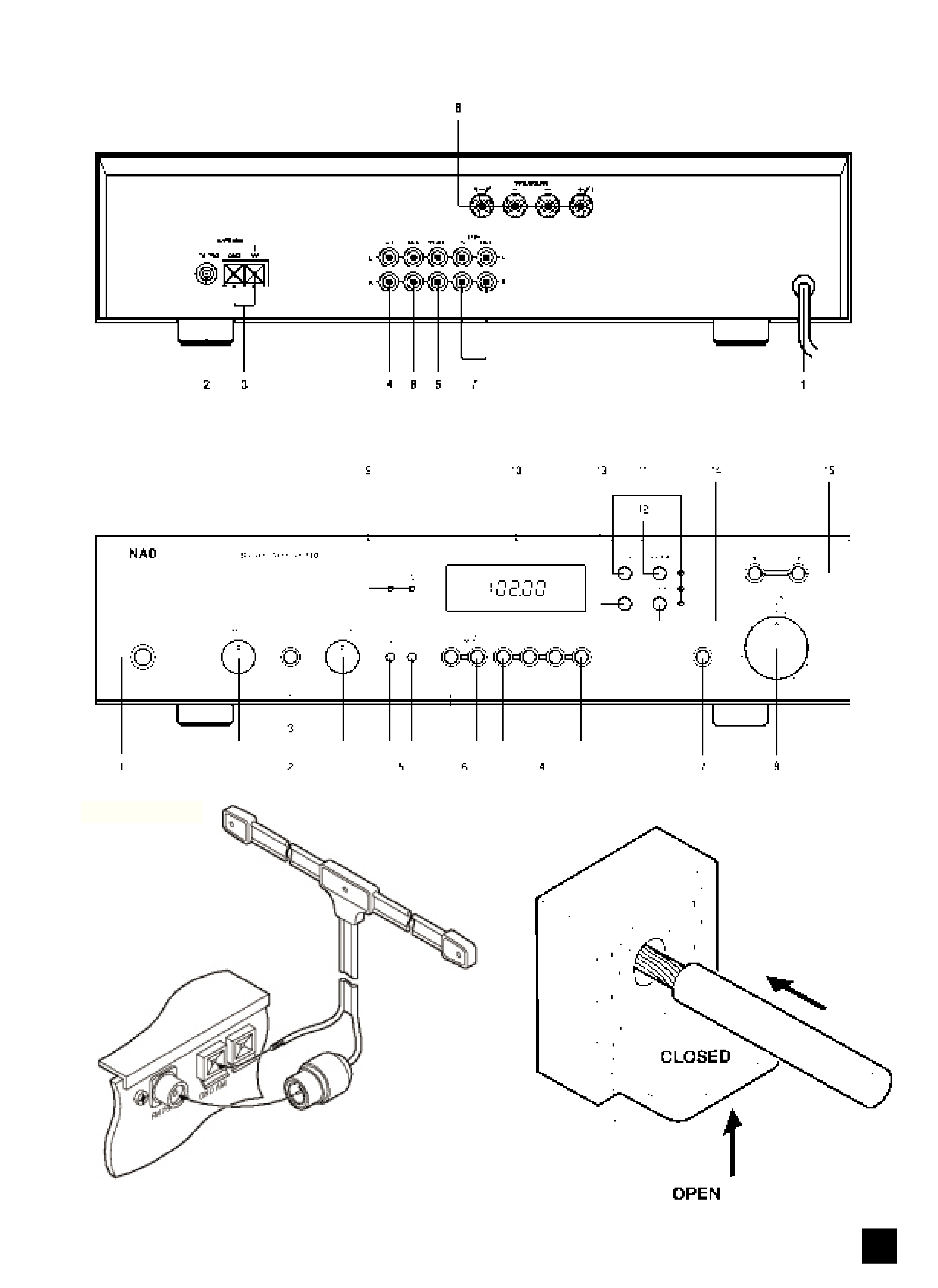
REAR PANEL CONNECTIONS - NAD 710
FRONT PANEL CONTROLS - NAD 710
NAD
3
Figure 1
Figure 2

NAD
4
GB
NAD 710 STEREO AM/FM RECEIVER
QUICK START
1. Connect the speakers and any other sources to
the relevant rear sockets.
2. Connect the AM and FM antenna.
3. Plug in the AC power cord.
4. Press the POWER button to turn the NAD-710 on.
5. Press an input selector or the tuner button.
NOTES ON INSTALLATION.
Your NAD-710 should be placed on a firm, level sur-
face. Avoid placing the unit in direct sunlight or near
sources of heat and damp.
Allow adequate ventilation. Do not place the unit on a
soft surface like a carpet. Do not put it in an enclosed
position such a bookcase or cabinet that may impede
the air-flow through the ventilation slots.
Switch the unit off before making any connections.
Use high quality RCA leads and connectors for opti-
mum performance and reliability. Ensure that leads and
connectors are not damaged in any way and all con-
nectors are firmly pushed home. The RCA connectors
on your NAD-710 are colour coded red and white for
Right and Left audio respectively.
For best performance, use quality speaker leads of
16 gauge thickness or more.
If the unit is not going to be used for some time, dis-
connect the plug from the AC socket.
Should water get into your NAD-710, shut off the
power to the unit and remove the plug from the AC
socket. Have the unit inspected by a qualified service
technician before attempting to use it again.
Do not remove the cover, there are no user-service-
able parts inside.
Use a dry soft cloth to clean the unit. If necessary,
lightly dampened the cloth with soapy water. Do not
use solutions containing benzol or other volatile agents.
REAR PANEL CONNECTIONS.
1. AC POWER CORD
Connect the AC Power cord to a suitable AC outlet
socket.
2. FM ANTENNA
A ribbon wire FM antenna is included and should be
connected to the FM connector at the rear of the unit
using the `balun' adapter supplied (see fig 1). The rib-
bon aerial should be mounted on a vertical surface and
placed so that it forms a `T'.
Experiment with placement of the antenna to find the
position that gives the best signal strength and lowest
background noise.
An inadequate FM signal normally results in high lev-
els of hiss, especially in stereo, and interference from
external electrical sources. The tuner section's perfor-
mance can be improved by using an externally mount-
ed FM antenna. A qualified aerial installer will be able
to advise and fit a recommended aerial for your recep-
tion conditions.
3. AM ANTENNA
An AM wire antenna is supplied with the NAD-710
and is required for AM reception. To connect the AM
antenna, press the key on the AM Antenna terminal
downwards. Insert the bare antenna wire into the AM
terminal hole and push the connector key upwards
again to secure the connection (see fig 2).
Test various positions for the antenna wire for best
reception. Placing the antenna close to large metal
items such as metal shelves or radiators may interfere
with reception .
Connecting the Ground (G) terminal to a true-ground
(such as an electrical ground terminal, a cold water
supply pipe or a copper-plated rod driven several feet
into the ground) may also improve reception.
To improve reception of distant AM stations, use a
longer wire (up to 30 meters) preferably placed horizon-
tally, high up and outside. A qualified aerial installer will
be able to advise on a recommended aerial for your
reception conditions.
4. CD INPUT
Input for a CD or other line-level signal source. Use a
twin RCA-to-RCA lead to connect the left and right ana-
logue Audio Outputs of a CD player to this input.
5. VIDEO INPUT
Input for the audio signal from a stereo VCR (or
stereo TV/Satellite/Cable receiver) or other line-level
audio source. Using twin RCA-to-RCA leads or a
SCART/RCA Adapter, connect to the left and right
`Audio Out' of the unit to these inputs.
Note: These are audio inputs only.
6. AUX INPUT
Input for additional line level input signals such as
another CD player. Use a twin RCA-to-RCA lead to
connect the auxiliary unit's left and right `Audio Outputs'
to this input.
7. TAPE IN, OUT
Connections for analogue recording and playback to
an audio tape recorder of any type. Using twin RCA-to-
RCA leads, connect to the left and right `Audio Output'
of the tape machine to the TAPE IN connectors for
playback and tape monitoring. Connect the left and
right `Audio Input' of the tape machine to the TAPE
OUT connectors for recording.
8. SPEAKERS
Outputs for speakers with an impedance of 4
or
more.
The `RIGHT+' terminal should be connected to the
`+' terminal on your right-hand loudspeaker and the
`RIGHT-' connected to the loudspeaker's `-' terminal.
Connect the terminals marked `LEFT+' and `LEFT-'
to the left-hand speaker in the same way.
Always use heavy duty stranded wire or specialist
speaker cables to connect the loudspeakers to your
NAD-710.
The high-current binding post terminals can be used
as a screw terminal for cables terminating in spade or
pin connectors, or for cables with bare wire ends.

NAD
5
GB
SPADE CONNECTORS.
These should be slotted under the terminal's screw
bushing, which is then fully tightened. Ensure the con-
nector is tightly secured and there is no danger of bare
metal from spade connectors touching the back panel
or another connector, as this may cause damage.
BARE WIRES AND PIN CONNECTORS.
Bare wires and pin connectors should be inserted
into the hole in the shaft of the terminal. Unscrew the
speaker terminal's plastic bushing until the hole in the
screw shaft is revealed. Insert the pin or bare cable end
into the hole and secure the cable by tightening down
the terminal's bushing.
Avoid any danger of bare metal from the speaker
cables touching the back panel or another connector.
Ensure that there is only 1/2" (1cm) of bare cable or pin
and no loose strands of speaker wire.
FRONT PANEL CONTROLS.
1. POWER
Press the POWER switch to turn the receiver On.
The Display Panel will illuminate. Press the POWER
switch again to turn the receiver Off.
The NAD-710 uses non-volatile memory to store pre-
set information for the tuner so that these are not lost
when the unit is switched off or unplugged.
2. BASS & TREBLE CONTROLS
The BASS and TREBLE tone controls adjust the
tonal balance of your system.
The 12 o'clock position is `flat' with no boost or cut
and a detent indicates this position. Rotate the controls
clockwise to increase, or anti-clockwise to decrease,
the amount of Bass or Treble. The Tone controls do not
affect recordings made using the TAPE or PORTABLE
Outputs.
3. TONE DEFEAT
The TONE DEFEAT switch by-passes the tone con-
trol section of the NAD-710. If you normally leave the
Tone Controls in the 12 o'clock position, then it is
advisable to switch out the tone control section alto-
gether by depressing the TONE DEFEAT switch. By-
passing the Tone Control electronics ensures a slightly
improved audio quality and an unaltered frequency
response.
4. INPUT SELECTORS
These buttons select the active input to the NAD-710
and the signal sent to the loudspeakers, the TAPE and
PORTABLE OUTPUTS. Press the button to latch it in
and select the input. It will be released when a different
input is selected.
VIDEO
Selects the VCR (or stereo TV/Satellite/Cable receiv-
er) connected to the VCR sockets as the active input.
AUX
Selects a line-level source connected to the AUX
sockets as the active input.
CD
Selects the CD (or other line-level source) connected
to the CD sockets, as the active input.
TUNER
Selects the NAD-710's Tuner Section as the active
input.
5. PORTABLE/INPUT CONNECTORS
Your
NAD-710
has
additional
front
panel
PLAY/RECORD connectors to playback or record
using a second system temporarily connected to the
receiver. 3.5mm stereo mini-jack sockets are provided
so that personal or portable stereo systems can be
easily connected to your receiver. Standard Hi-Fi com-
ponents that have RCA sockets can also be connected
to these PLAY/RECORD sockets using a suitable
3.5mm/twin RCA adapter.
Press the PORTABLE button In to select the front
panel Portable Input, and Out to return to normal oper-
ation.
The PORTABLE input will mix with any other input
signal selected. So for example, by pressing CD and
then selecting PORTABLE, you can use the NAD-710
to mix between two CD players (one connected CD
and the other connected to PORTABLE).
6. TAPE MONITOR
Selects the output from a tape recorder when playing
back tapes or monitoring recordings being made
through the rear TAPE sockets. Press the TAPE MONI-
TOR button once to select it, and again to return to the
normal input selection.
This is a Tape Monitor function and will not cancel
the current input selection. For example, if the CD is
the active input when TAPE MONITOR is selected, CD
will remain selected and its signal sent to the TAPE
and PORTABLE output sockets. However the sound
heard through the loudspeakers will be coming back
from recorder connected to your receivers TAPE IN
sockets.
TO MAKE A RECORDING.
When any source is selected, the signal is also fed
directly to any tape machine connected to the TAPE or
PORTABLE output, ready for recording.
TAPE-TO-TAPE COPYING.
You can copy between two tape machines connected
to your NAD-710. Put the source tape in the recorder
connected to PORTABLE and the blank tape into the
recorder connected to TAPE. By selecting the
PORTABLE input and then TAPE MONITOR you can
now record from Portable to Tape and monitor the sig-
nal being recorded.
Note: Copying may be violating the copyright or prop-
erty rights of the recordings owner.
VOLUME AND MONO.
7. MONO
Pressing the MONO button in switches the NAD-710
amplifier and tuner sections between Stereo and Mono
Modes. Use Mono mode when the signal is present on
only one of the two stereo input channels (left or right)
or when receiving weak and hissy stereo FM signals.
Pressing the button out returns to Stereo operation.