
GB
F
D
E
I
S
NAD
310
· OWNER'S MANUAL
· MANUEL D'INSTALLATION
· BEDIENUNGSANLEITUNG
· MANUAL DEL USUARIO
· MANUALE DELLE ISTRUZIONI
· BRUKSANVISNINGARNA
REAR PANEL CONNECTIONS
WARNING:TO PREVENT FIRE OR ELECTRIC
SHOCK, DO NOT EXPOSE THIS APPLIANCE
TO RAIN OR MOISTURE
CAUTION: TO PREVENT ELECTRIC SHOCK,
MATCH WIDE BLADE OF PLUG TO WIDE
SLOT, FULLY INSERT.
ATTENTION: POUR EVITER LES CHOCS
ELECTRIQUES, INTRODUIRE LA LAME LA
PLUS LARGE DE LA FICHE DANS LA BORNE
CORRESPONDANTE DE LA PRISE ET
POUSSER JUSQU'AU FOND.
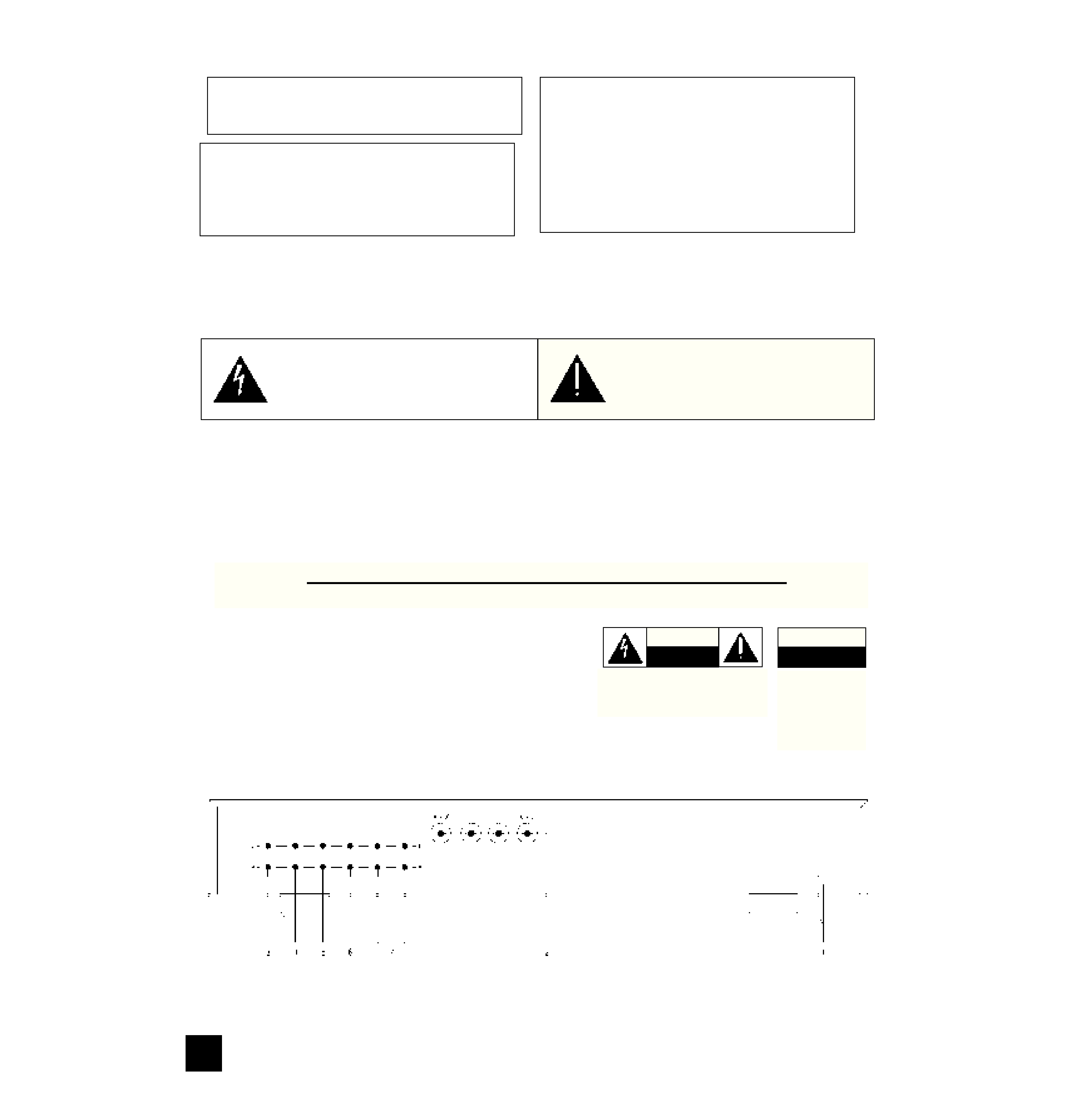
The lightning flash with arrowhead, within an equilateral tri-
angle is intended to alert the user of the presence of unin-
sulated "dangerous voltage" within the product's enclo-
sure; that may be of sufficient magnitude to constitute a
risk of electric shock to persons.
The exclamation point within an equilateral triangle is intend-
ed to alert the user of the presence of important operating
and maintenance (servicing) instructions in the literature
accompanying the appliance
Note to CATV system installer: This reminder is provided
to call the CATV installer's attention to Article 820-40 of the
NEC , which provides guidelines for proper grounding and,
in particular, specifies that the cable should be connected
to the grounding system of the building, as close to the
point of cable entry as practical.
NAD
2
NAD 310 STEREO INTEGRATED AMPLIFIER
CAUTION
RISK OF ELECTRIC
SHOCK DO NOT OPEN
ATTENTION:
RISQUE DE CHOC ELECTRIQUE
NE PAS OUVRIR
CAUTION: TO REDUCE THE RISK OF ELECTRIC
SHOCK, DO NOT REMOVE COVER (OR BACK).
NO USER SEVICEABLE PARTS INSIDE.
REFER SERVICING TO QUALIFIED
SERVICE PERSONNEL.
AFIN DEVITER UN CHOC
ELECTRIQUE, ET LES
CONSEQUENCES GRAVES
QUI POURRAIENT EN
RESULTER, TENTEZ PAS
D'OUVRIR L'APPAREIL ET
DE TOUCHER AUX
COMPOSANTS INTERNES
SANS LA PRESENCE D'UNE
SERVICE PERSONNEL.
NAD
3
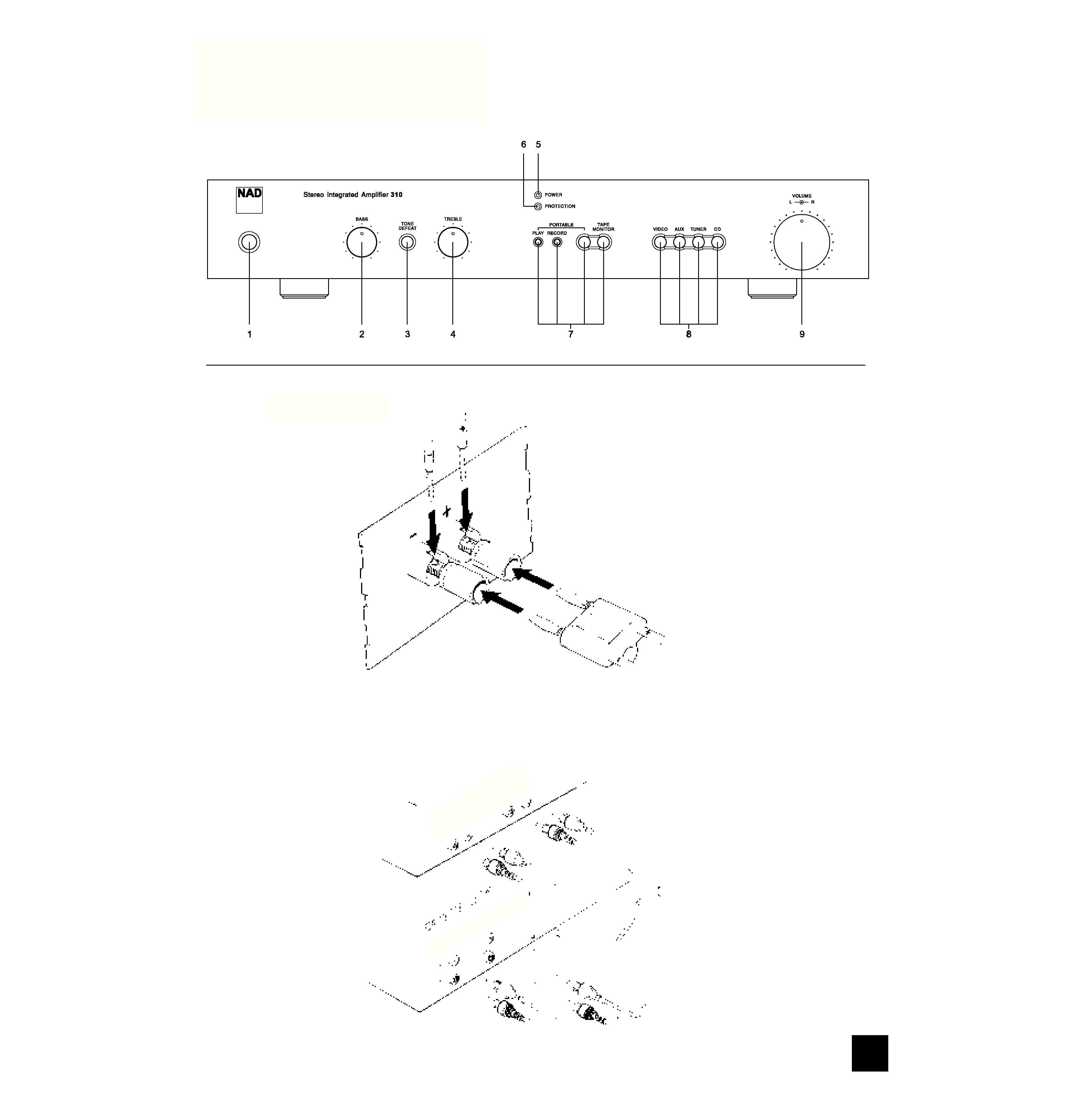
FRONT PANEL CONTROLS
FIGURE 1.
FIGURE 2.
PL
AY
TA
PE
RE
C
R
L
R
L
IN
PU
T T
AP
E O
UT
PU
T

INSTRUCTIONS FOR INSTALLATION
AND OPERATION
A NOTE ON INSTALLATION
This unit may be installed on any stable surface.
Since its power transformer (near the left-rear corner)
generates a magnetic hum field of moderate strength,
an LP turntable should not be located directly to its
left.
The amplifier also generates a modest amount of
heat and thus requires some ventilation. Do not
place it on a rug or other soft surface that it could sink
into, obstructing the air inlets on its bottom. And do
not allow papers or cloth to obstruct the ventilation
grille in the top cover.
CAUTION: To prevent a fire or shock hazard, do
not permit this product to become wet. If liquid is
accidentally spilled on it, immediately shut off its
power and unplug the AC power cord. Allow suffi-
cient time for complete evaporation to occur before
operating the amplifier again. If the liquid is anything
but water and/or alcohol, the amplifier should be
examined by a service technician before power is
applied to it.
Do not remove the cover, or attempt to modify or
repair the amplifier yourself. Refer all servicing to a
qualified technician.
REAR PANEL CONNECTIONS
1. AC LINE CORD
After you have completed all connections to the
amplifier, plug the AC line cord into a "live" wall sock-
et or into a heavy-duty extension cord.
WARNING TO UK USERS. If this appartus is not
fitted with a UK three-pin plug, do not attempt to
insert the attached plug into a UK mains socket.
Instead, cut the plug from the mains lead and attach
a fused UK three-pin plug using the following safety
advice on wiring.
IMPORTANT. The wires in this mains lead are
coloured BLUE and BROWN;
BLUE: NEUTRAL
BROWN: LIVE
The colours of these mains lead wires may not corre-
spond with the coloured markings identifying the ter-
minals in your plug. In this case the BROWN wire
must be connected to the terminal which is marked
L(ive) or coloured RED. The BLUE wire must be con-
nected to the terminal marked N(eutral) or coloured
BLACK. No connection should be made to the termi-
nal marked E or coloured green or green and yellow
2. SPEAKER TERMINALS.
Use these high-current binding-post terminals to
connect your main stereo speakers.
Each binding
post consists of a threaded metal shaft and a red or
black plastic screw-on bushing.
Connect the wires from your left-channel speaker
to the (L+) and (L-) terminals, and connect the wires
from the right-channel speaker to the (R+) and (R-)
terminals. In each channel the red terminal is the
positive (+) output, and the black terminal is the nega-
tive (-) or "ground" terminal. For best stereo imaging,
the left and right speakers should be located at equal
distances from your chair.
Use heavy-duty (1.5mm2, 16-gauge, or thicker)
stranded wire, especially with 4-ohm loudspeakers.
Bare wires can be connected directly to the binding-
post terminals. For a longer-lasting and more corro-
sion-resistant connection you may purchase speaker
cables with nickel or gold-plated connectors (spade
lugs, banana plugs, or pin connectors), or install such
connectors on the wires yourself. Connections to
each binding post may be made in several ways, as
follows. [Figure 1.]
(1) Pin connectors. A pin connector is a slim metal
shaft that is crimped or soldered onto the end of a
wire. The binding posts accept pin connectors up to
3mm in diameter. Unscrew the plastic bushing on
each terminal to expose the hole in the metal shaft.
Insert the pin connector through the hole, and turn
the bushing clockwise until it is tight.
(2) Spade lugs. Unscrew the colored bushing,
insert the U-shaped spade lug behind the bushing,
and tighten the bushing down on it.
(3) Banana plugs. Insert a banana plug directly
into the hollow end of each binding post. The termi-
nals are separated by 3/4 inch (19mm), so they will
accept dual-banana plugs. Before using banana
plugs, the red and black inserts have to be removed
with the aid of a small screwdriver.
(4) Bare wires. Separate the two conductors of the
cord, and strip off a half-inch (1 cm) of insulation from
each. In each conductor, twist together the exposed
wire strands. Unscrew the red or black bushing,
insert the bare wire through the hole in the metal
shaft, and tighten the plastic bushing until it grasps
the wire securely. Check to be sure that no loose
strand of wire is touching the chassis or an adjacent
terminal.
Phasing. Stereo speakers must operate "in phase"
with each other in order to produce a focused stereo
image and to reinforce rather than cancel each
other's output at low frequencies. An in-phase con-
nection is assured if the red (positive) terminal on the
amplifier is connected to the red (positive) terminal on
the loudspeaker, in each channel. Methods of check-
ing for correct phasing are described in the Appendix.
3. CD INPUT.
Connect the audio signal cables from a Compact
Disc player to these jacks. (NOTE: this input is for an
audio signal, not for the digital-code output of a CD
player.) If you don't have a CD player, any other line-
level signal source (such as a MiniDisc player or a
spare tape deck) may be connected to the CD input.
4. TUNER INPUT.
Connect the audio signal cable from a radio tuner
(AM, FM, or digital radio) to this pair of jacks.
NAD
4
GB
NAD 310 STEREO INTEGRATED AMPLIFIER

5. AUX INPUT.
Any "line-level" audio signal can be connected
here, such as the playback signal from a second CD
player, or with an external step-up amplifier, a
turntable.
6. VIDEO SOUND INPUT.
Connect a video-related audio signal here, such
as the audio output from a video cassette recorder,
laserdisc player, TV monitor/receiver, or stereo televi-
sion decoder. Alternatively, any "line-level" audio sig-
nal may be connected here, such as the playback
from a spare tape deck.
7. TAPEPLAY/REC.
These jacks allow you to connect tape recorder of
any type, especially a high-performance cassette or
open-reel recorder whose independent recording and
playback heads allow you to monitor the signal on the
tape immediately after it is recorded. Connect a
stereo cable from the TAPE REC jacks of this amplifi-
er to the recorder's LINE IN jacks, and a second
cable from the recorder's LINE OUT jacks to these
TAPE PLAY jacks.
The TAPE jacks may be used for a signal-process-
ing accessory instead of a tape recorder. Examples
of such accessories include a dynamic range proces-
sor, a noise filter, or a graphic equalizer. Connect a
patch cord from the TAPE REC jacks to the proces-
sor's inputs, and another patch cord from processor's
outputs to the TAPE PLAY jacks.
FRONT PANEL CONTROLS
1. POWER.
Press this button to switch on the amplifier. To
switch the power off, press the button again and
release it.
NOTE: When the amplifier is switched off with a
source (such as a CD) still playing there will still be
sound for as much as several seconds, depending on
the volume level, before it eventually dies out.
Although completely harmless, it can be avoided
switching off the source first or by turning down the
volume first.
CAUTION: In the off position the unit is still con-
nected to the mains. Disconnect the power cable
when the unit is not to be used for a long time.
2. BASS.
The Bass control adjusts the relative level of the
low frequencies in the sound. The response of the
amplifier is flattest when the control is set in the
detent at the 12 o'clock position. Rotation of the knob
to the right (clockwise) increases the level of low-fre-
quency sounds, and rotation counter-clockwise
decreases their level.
The Bass control has no effect if the TONE
DEFEAT button is engaged.
At moderate rotations away from center the effect
of the Bass control is subtle, because its action is
confined to the lowest audible frequencies, which are
not present in some recordings. Only at large rota-
tions away from center is there a substantial boost or
cut at the mid-bass frequencies that are common in
music.
3. TONE DEFEAT.
When this button is pressed the Bass and Treble
circuits are completely bypassed, restoring precisely
flat frequency response. When this button is OUT the
tone controls operate normally. By adjusting the tone
controls and then switching them in and out of the
signal path, you can evaluate their effect on the
sound.
4. TREBLE.
The Treble control adjusts the relative level of the
high frequencies in the sound. The response of the
amplifier is flattest when the control is set in the
detent at the 12 o'clock position. Rotation of the
Treble control to the right (clockwise) increases the
level of high-frequency sounds, and rotation counter-
clockwise decreases their level. Adjust the Treble
control to achieve the tonal balance that sounds most
natural to you.
Boosting the Treble increases the brilliance and
clarity of details in the sound, but also makes any
noise more prominent. Turning down the Treble
makes the sound mellower while suppressing hiss
and record surface noise; but too much Treble roll-off
will make the sound dull.
The Treble control has no effect if the TONE
DEFEAT button is engaged.
NOTE: At high volume settings (with the volume
control over the 12 o'clock position) both the Bass
and Treble controls do not have any effect anymore.
5. POWER INDICATOR.
The POWER indicator glows green when the ampli-
fier is switched on and ready for use.
6. PROTECTION INDICATOR.
The amplifier incorporates protection circuitry
against conditions such as overheating, short circuits,
and DC off-set. Under normal conditions, this indica-
tor will not light up and the unit will operate normally.
If however one of the decribed conditions occur, the
indicator will light up red and the unit will stop work-
ing.
TURN DOWN the volume all the way and SWITCH
OFF the amplifier IMMEDIATLY.
Investigate the cause for the protection circuitry to
trip, such as a short circuit in any of the speaker
leads or any wire touching an adjecant terminal at
either the amplifier's or loudspeaker's end.
If overheating was the cause (the amplifier's casing
will be very warm) ensure the ventilation slots at the
bottom and top are not blocked. Overheating can also
occur by playing very loud for a prolonged time. Wait
for a couple of minutes for the amplifier to cool down
before switching it on again.
If the protection circuitry remains engaged, even
after the amplifier has cooled down sufficiently and all
NAD
5
GB