GB
F
D
E
I
S
P
NAD
218 THX
· OWNER'S MANUAL
· MANUEL D'INSTALLATION
· BEDIENUNGSANLEITUNG
· MANUAL DEL USUARIO
· MANUALE DELLE ISTRUZIONI
· BRUKSANVISNING
· MANUAL DO PROPRIETÁRIO
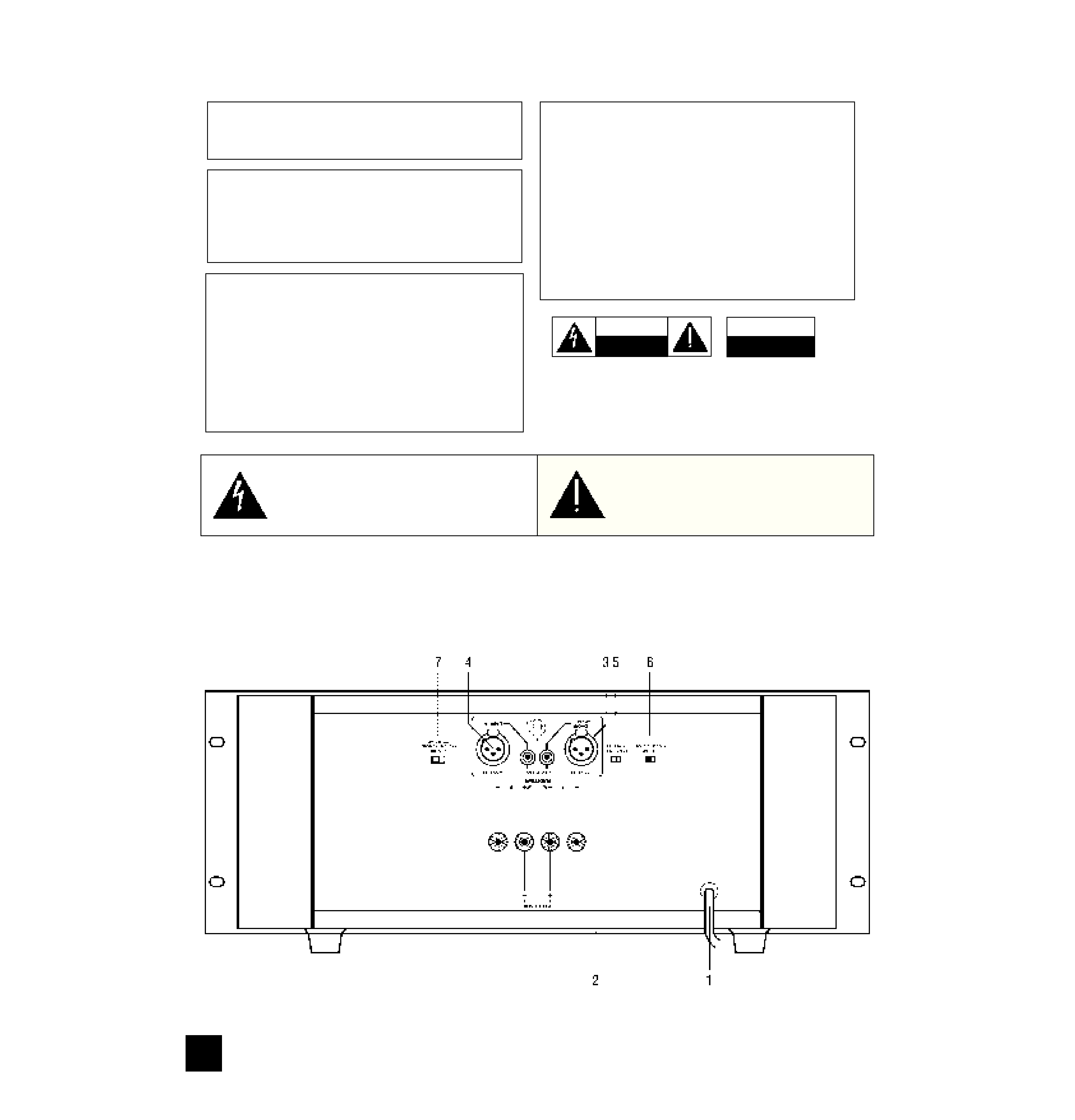
REAR PANEL CONNECTIONS
WARNING:TO PREVENT FIRE OR ELECTRIC
SHOCK, DO NOT EXPOSE THIS APPLIANCE
TO RAIN OR MOISTURE
CAUTION: TO PREVENT ELECTRIC SHOCK DO
NOT USE THIS POLARISED PLUG WITH AN
EXTENSION CORD RECEPTACLE OR OTHER
OUTLET UNLESS THE BLADES CAN BE FULLY
INSERTED TO PREVENT BLADE EXPOSURE.
ATTENTION: POUR PREVENIR LES CHOCS ELEC-
TRIQUES NE PAS UTILISER CETTE FICHE
POLARISEE AVEC UN PROLONGATEUR, UNE
PRISE DE COURANT OU UNE AUTRE SORTIE DE
COURANT, SAUF SI LES LAMES PEUVENT ETRE
INSEREES A FOND SANS EN LAISSER AUCUNE
PARTIE A DECOUVERT.
The lightning flash with arrowhead, within an equilateral tri-
angle is intended to alert the user of the presence of unin-
sulated "dangerous voltage" within the product's enclo-
sure; that may be of sufficient magnitude to constitute a
risk of electric shock to persons.
The exclamation point within an equilateral triangle is intend-
ed to alert the user of the presence of important operating
and maintenance (servicing) instructions in the literature
accompanying the appliance
Note to CATV system installer: This reminder is provided
to call the CATV installer's attention to Article 820-40 of the
NEC , which provides guidelines for proper grounding and,
in particular, specifies that the cable should be connected
to the grounding system of the building, as close to the
point of cable entry as practical.
NAD
2
CAUTION
RISK OF ELECTRIC
SHOCK DO NOT OPEN
ATTENTION:
RISQUE DE CHOC ELECTRIQUE
NE PAS OUVRIR
CAUTION: TO REDUCE THE RISK OF ELECTRIC
SHOCK, DO NOT REMOVE COVER (OR BACK).
NO USER SEVICEABLE PARTS INSIDE.
REFER SERVICING TO QUALIFIED
SERVICE PERSONNEL.
AFIN DEVITER UN CHOC
ELECTRIQUE, ET LES
CONSEQUENCES GRAVES
QUI POURRAIENT EN
RESULTER, TENTEZ PAS
D'OUVRIR L'APPAREIL ET
DE TOUCHER AUX
COMPOSANTS INTERNES
SANS LA PRESENCE D'UNE
SERVICE PERSONNEL.
THIS DIGITAL APPARATUS DOES NOT EXCEED THE CLASS B
LIMITS FOR RADIO NOISE EMISSIONS FROM DIGITAL
APPARATUS AS SET OUT IN THE RADIO INTERFERENCE
REGULATIONS OF THE CANADIAN DEPARTMENT OF
COMMUNICATIONS.
LE PRESENT APPAREIL NUMVERIQUE N'EMET PAS DE
BRUITS RADIOELECTRIQUES DEPASSANT LES LIMITES
APPLICABLES AUX APPAREILS NUMERIQUES DE LA CLASSE
B PRESCRITES DANS LE REGLEMENT SUR LE BROUILLAGE
RADIO ELECTRIQUE EDICTE PAR LE MINISTERE DES
COMMUNICATIONS DU CANADA.
NAD
3
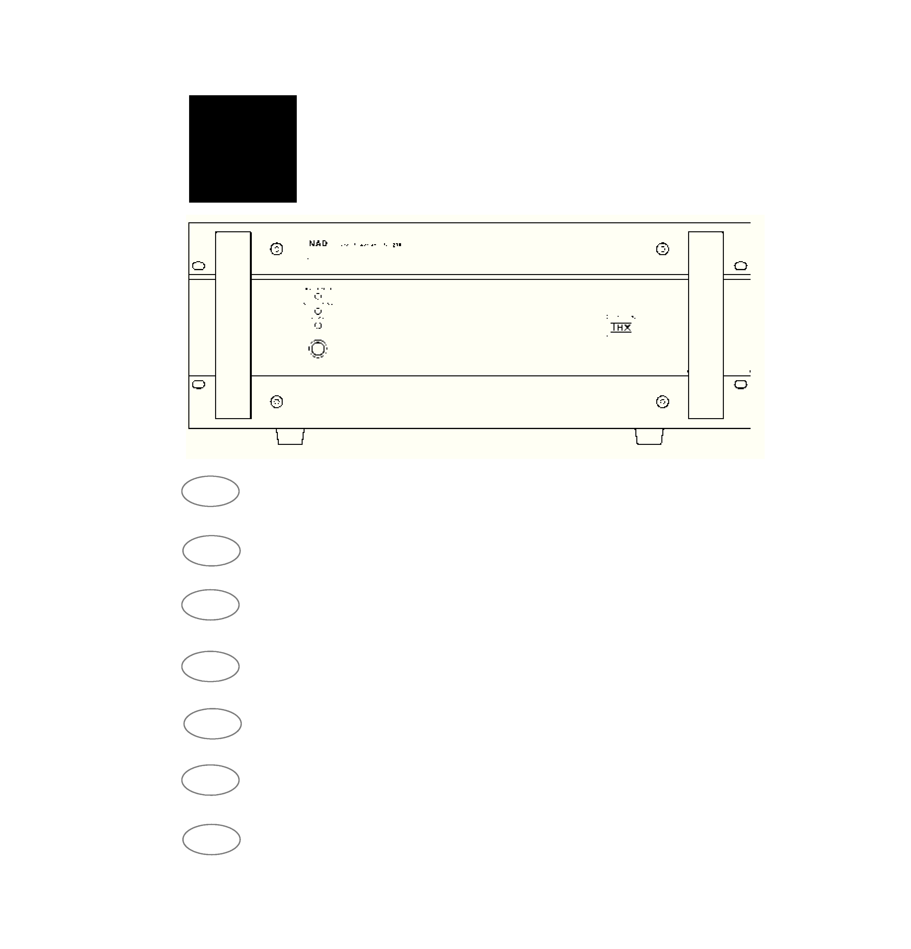
FRONT PANEL CONTROLS
Figure 1.
(120V version only)

A NOTE ON INSTALLATION
This unit may be installed on any level surface that
is strong enough to support its weight. Since its
power transformer generates a significant magnetic
hum field, a turntable (especially one with a moving-
coil pickup cartridge) should not be located adjacent
to the amplifier nor directly above it.
The heat-sink fins make it awkward to lift the 218
THX by grasping the left and right sides. You may
find it more practical to place your hands under the
front and rear panels. Much of the amplifier's weight
is near the front panel.
CAUTION: The amplifier's weight must always rest
on its bottom feet. Never put the amp down on its
rear panel, with its front panel facing up. Doing so
risks damage to the input/output connectors.
The amplifier generates a moderate amount of
heat, requiring internal ventilation. Do not permit the
air outlet grille on the top cover to be obstructed by
papers or articles of clothing. If you want to locate
the amplifier on a carpeted floor, place a board under
the amp in order to prevent it from sinking into the
carpet, blocking the air inlets on its bottom.
CAUTION: To prevent a fire or shock hazard, do
not permit liquid or moisture to enter the amplifier. If
liquid is accidentally spilled on it, immediately shut off
the power and unplug the AC power cord. Allow time
for complete evaporation to occur before operating
the amplifier again. (If the liquid is anything but water
and/or alcohol, the amplifier should be examined by a
service technician before power is applied to it.)
Do not open the amplifier, or attempt to modify or
repair it yourself. Refer all servicing to a qualified
technician.
REAR PANEL CONNECTIONS
1. AC POWER CORD
Plug the AC power cord into a live wall socket. If
you must use an extension cord, select a heavy-duty
cord of the type used for large electrical appliances.
Do not connect the amplifier's power cord to the
accessory AC outlets on a preamplifier. Such conve-
nience outlets are not designed to supply the high
power levels, up to 800 watts, that the 218 THX
requires. If you wish to switch your entire audio sys-
tem on and off at once, plug both the 218 THX and
your preamp into a "power strip" containing several
grounded AC outlets and a high-current on/off switch.
Voltage conversion. A notice printed on the rear
indicates the AC power-line voltage that the amplifier
requires. However every Model 218 THX amplifier
has a "universal" power supply that can be modified
easily for operation in other countries. If you wish to
transport your 218 THX to a nation that employs a dif-
ferent power-line voltage, an authorised NAD dealer
or service agency can convert it for such use.
2. SPEAKERS
This amplifier is equipped with special high-current
binding-post speaker terminals to handle the highest
peak power levels that may occur in the "bridged"
mode or with low-impedance speakers. At moments
when the amplifier is producing maximum power,
voltages of nearly 100V may be present on the
speaker terminals, so the terminals are protected by
hinged plastic safety covers.
To connect loudspeaker cables, first switch off the
amplifier's power. If you are connecting a pair of
speakers for normal stereo operation, be sure that
the Bridging switch is set to OFF (STEREO). Raise
the
plastic
cover
to
gain
access
to
the
SPEAKERSterminals.
For best stereo imaging, the left and right speakers
should be located at equal distances from your chair.
To minimize the effect of speaker cables on the
sound, locate the amplifier near the speakers and use
short cables to connect the speakers. If your pream-
plifier is located at the opposite end of the room near
your chair, you will need a long cable to connect it to
the power amplifier.
All NAD preamplifiers have the
low output impedance required to drive long connect-
ing cables.
Connect the wires from your left-channel speaker
to the (L+) and (L-) terminals in the SPEAKERS
group, and connect the wires from the right-channel
speaker to the (R+) and (R-) terminals. In each chan-
nel the red terminal is the positive (+) output, and the
black terminal is the negative (-) or "ground" terminal.
Use heavy-duty (16-gauge or thicker) stranded
wire, especially with 4-ohm loudspeakers. Bare wires
can be connected directly to the binding-post termi-
nals. For a longer-lasting and more corrosion-resis-
tant connection you may purchase speaker cables
with nickel or gold-plated connectors (pin connectors,
spade lugsfor 230V versions, or banana plugs for
120V versions), or you can install such connectors on
the wires yourself. Connections to each binding post
may be made in several ways, as follows.
(1) Pin connectors. A pin connector is a slim metal
shaft that is crimped or soldered onto the end of a
wire. The threaded shaft of each binding post con-
tains an opening that accepts pin connectors up to
3mm in diameter. Unscrew the red or black plastic
bushing on each terminal to expose the hole in the
metal shaft. Insert the pin connector through the
hole, and turn the bushing clockwise until it is tight.
(2) Spade lugs. Unscrew the colored bushing,
insert the U-shaped spade lug behind the bushing,
and tighten the bushing down on it.
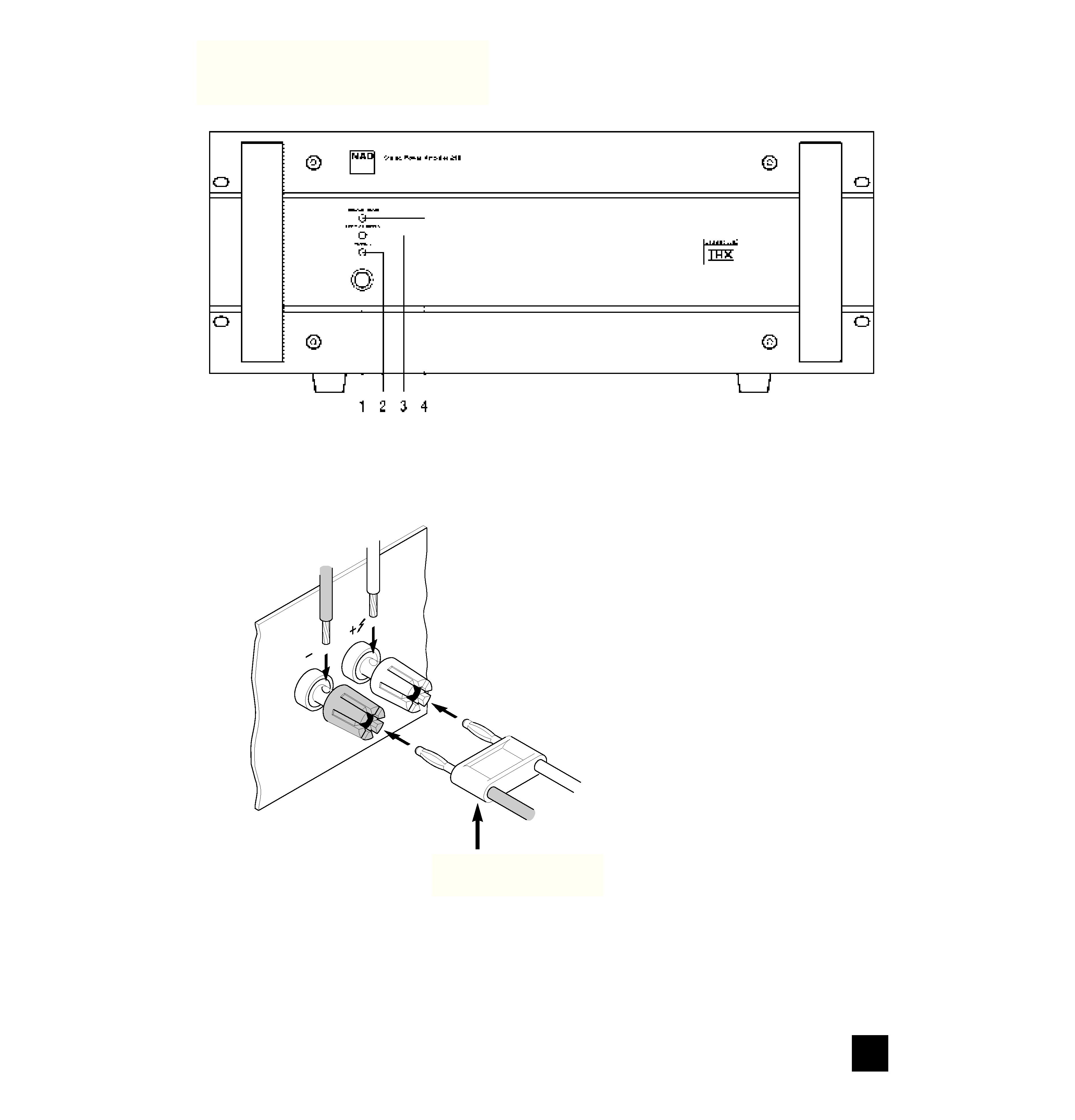
(3) Bare wires [See Figure 1]. Separate the two
conductors of the cord, and strip off a half-inch (1 cm)
of insulation from each. In each conductor, twist
together the exposed wire strands. Unscrew the red
or black bushing, insert the bare wire through the
hole in the metal shaft, and tighten the plastic bush-
ing until it grasps the wire securely. Check to be sure
that no loose strand of wire is touching the chassis or
an adjacent terminal. (Loose strands can be prevent-
ed by "tinning" the bare wire with melted solder
before you connect it to the amplifier.)
CAUTION: Safety organizations recommend that
the speaker terminals of a very powerful amplifier
should be covered. Potentially dangerous voltages
NAD
4
GB
NAD 218 THX POWER AMPLIFIER

are present on these terminals when the amplifier is
producing maximum power. After you have connect-
ed the speaker cables, bend the protective cover
down against the rear panel and fasten it in place. It
is particularly important that curious children and
small pets be prevented from touching the terminals.
Phasing. Stereo speakers must operate "in phase"
with each other in order to produce a focused stereo
image and to reinforce rather than cancel each
other's output at low frequencies. An in-phase con-
nection is assured if the red (positive) terminal on the
amplifier is connected to the red (positive) terminal on
the loudspeaker, in each channel.
If your speakers are easily moved, their phasing
can easily be checked. Make the connections to both
speakers, place the speakers face-to-face only a few
inches apart, play some music, and listen. Then
swap the connection of the two wires at the back of
ONE of the speakers, and listen again. The connec-
tion which produces the fullest, boomiest bass output
is the correct one. Connect the wires securely to the
speaker terminals, being careful not to leave any
loose strands of wire that might touch the wrong ter-
minal and create a partial short-circuit; then move
the speakers to their intended locations.
If the speakers cannot easily be set face-to-face,
then phasing must rely on the "polarity" of the con-
necting wires. The speaker terminals on the amplifier
are identified as red (+) and black (-) in each channel.
The terminals at the rear of the speakers are also
marked for polarity, either via red and black connec-
tors or by labels: "+", 1, or 8 ohms for positive, "-", 0,
or G for negative. The red (+) terminal on the amplifi-
er should be connected to the red (positive) terminal
of the speaker, in each channel.
To facilitate this, the two conductors comprising the
speaker wire in each channel are different, either in
the color of the wire itself (copper vs. silver) or in the
presence of a small ridge or rib pattern on the insula-
tion of one conductor. Use this pattern to establish
consistent wiring to both speakers of a stereo pair.
Thus if you connect the copper colored wire (or
ribbed insulation) to the (+) amplifier terminal in the
Left channel, do the same in the Right channel. At
the other end of the wire, if you connect the copper
colored wire (or the ribbed insulation) to the red or
positive terminal on the left-channel speaker, do the
same at the right-channel speaker.
3. LEFT CHANNEL INPUTS (Balanced,
Unbalanced).
Before making or changing input connections to the
amplifier, make certain that the Power is OFF.
The 218 THX amplifier is equipped with two input
connectors for each channel. The RCA phono jack is
a conventional "unbalanced" input. The three-hole
XLR socket is a professional "balanced" input. You
may use either type of input, but not both.
If your preamplifier has only conventional outputs
with RCA phono jacks, connect an audio connecting
cable from the left channel output of the preamp to
the left channel UNBALanced input of the 218 THX.
Set the BALANCE switch to UNBAL.
If your preamplifier has balanced XLR outputs, con-
nect a three-conductor cable from your left-channel
preamp output to the left-channel XLR input on the
218 THX, and set the BALANCE switch to BAL. If
your audio dealer does not have the appropriate
cables, purchase balanced "microphone" cables from
a shop that sells professional recording equipment.
The end of the cable that has a "male" XLR plug (with
three metal pins) should be connected to the 218
THX amplifier. The end of the cable that has a
"female" XLR socket (with three holes) should be
connected to your preamp.
An XLR plug is "keyed" so that it fits into the socket
only one way. If there is a set-screw in the barrel of
the plug, align it with the top of the connector. Push
the plug fully into the XLR socket until it latches in
place.
The three pins of an XLR-type ("Cannon") connec-
tor are numbered. Pin 2 is the signal "hot" connec-
tion; in the 218 THX, Pin 2 is connected directly to the
center pin of the unbalanced RCA phono jack. Pin 3
is the signal return (signal ground) connection. Pin 1
is the chassis earth (ground), to which the shield of a
balanced-wire cable is connected.
UNPLUGGING. The XLR socket has a latching
feature that prevents the connector from being pulled
out by accident. Before disconnecting an input cable,
turn off the Power. Use one hand to press the latch-
ing tab above the XLR socket while using the other
hand to pull the XLR plug out.
4. RIGHT CHANNEL INPUTS (Balanced,
Unbalanced).
Make connections to the right-channel input in the
same way that you did for the left channel.
5. INPUT SELECT (Balanced/Unbalanced).
Set this switch to match your selection of input
connector. Set to UNBAL if you have connected a
cable from your preamp to the RCA phono input
jacks. Set the switch to BAL if you are making con-
nections to the balanced XLR inputs.
Normally the choice of input connector is deter-
mined by the output connectors on your preamp. If
your preamp has balanced outputs, use three-con-
ductor cables equipped with XLR connectors. If your
preamp has only "unbalanced" connections with RCA
phono jacks, use the corresponding inputs on the 218
THX.
It is possible to connect an "unbalanced" source
(such as a CD player) to the XLR inputs, by means of
adapter cable in which the audio-return wire (Pin 3)
and the cable shield (Pin 1) are both connected to the
collar of the RCA phono plug at the source end of the
cable. With such a connection you may wish to
experiment with the setting of the BAL/UNBAL switch.
In the UNBAL position Pins 3 and 1 are short-circuit-
ed together at the amplifier input, effectively convert-
ing a three-wire cable into a conventional two-con-
ductor cable.
GB
NAD
5