NAD
118
· OWNER'S MANUAL
· MANUEL D'INSTALLATION
· BEDIENUNGSANLEITUNG
GB
F
D
©
1996.
118.
NAD
ELECTRONICS
LTD

Warning: To reduce the risk of fire or electric shock, do not expose
this unit to rain or moisture.
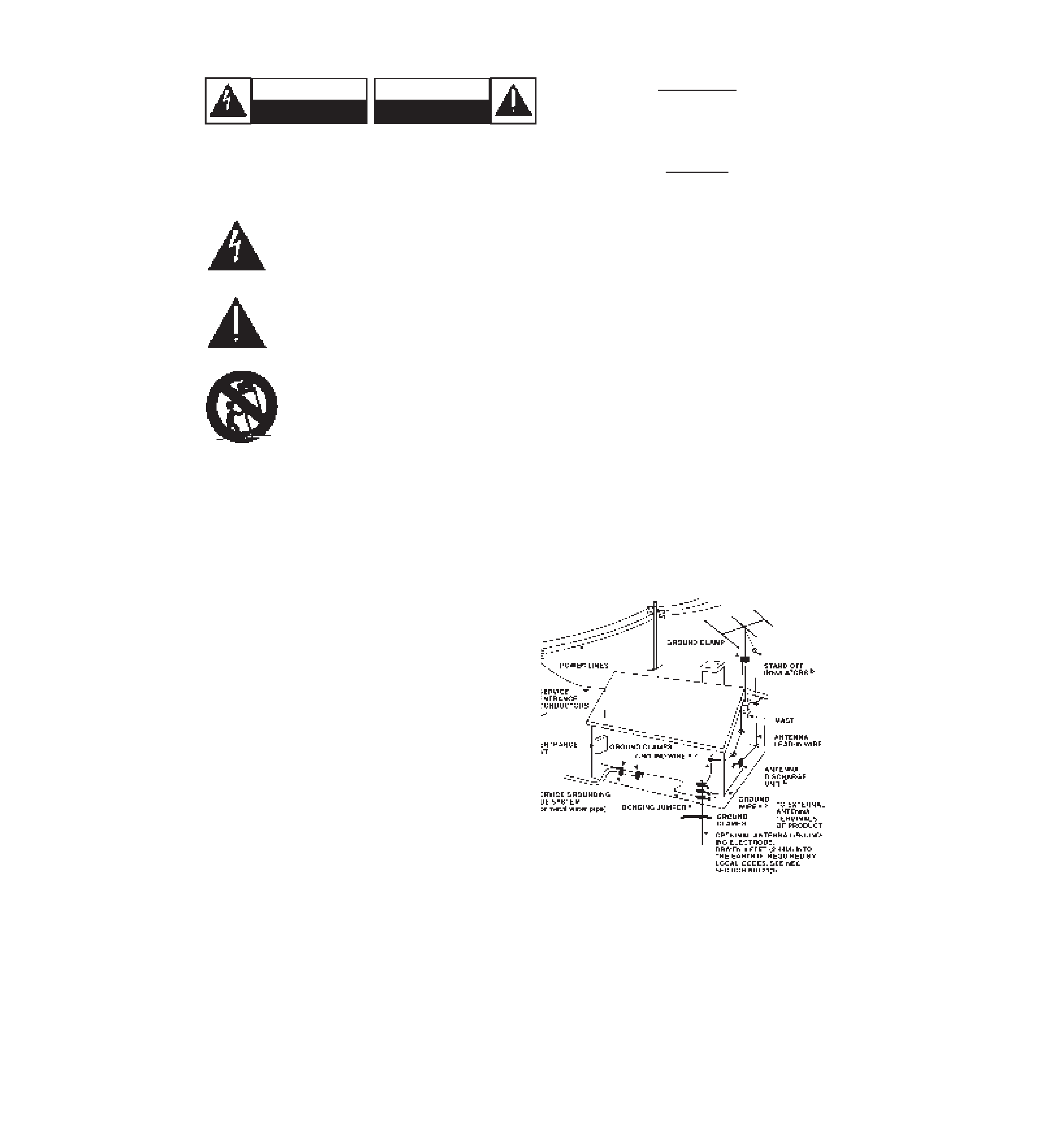
The graphic symbol of a lightning flash with an arrow point within
a triangle signifies that there is dangerous voltage within the
unit and it poses a hazard to anyone removing the cover to
gain access to the interior of the unit. Only qualified
service personnel should make any such attempt.
The graphic symbol of an exclamation point within an equilateral
triangle warns a user of the device that it is necessary to refer
to the instruction manual and its warnings for proper opera-
tion of the unit.
Do not place this unit on an unstable cart, stand or tri-
pod, bracket or table. The unit may fall, causing seri-
ous injury to a child or adult and serious damage to the
unit. Use only with a cart, stand, tripod, bracket or
table recommended by the manufacturer or sold with
the unit. Any mounting of the device on a wall or ceil-
ing should follow the maufacturer's instructions and
should use a mounting accessory recommended
by the manufacturer.
An appliance and cart combination should be moved with care. Quick
stops, excessive force and uneven surfaces may cause the appliance
and cart combination to overturn.
Read and follow all the safety and operating instructions before connect-
ing or using this unit. Retain this notice and the owner's manual for future
reference.
All warnings on the unit and in it's operating instructions should be
adhered to.
Do not use this unit near water; for example, near a bath tub, washbowl,
kitchen sink, laundry tub, in a wet basement or near a swimming pool.
The unit should be installed so that its location or position does not inter-
fere with its proper ventilation. For example, it should not be situated on
a bed, sofa, rug or similar surface that may block the ventilation open-
ings; or placed in a built-in installation, such as a bookcase or cabinet,
that may impede the flow of air through its ventilation openings.
The unit should be situated from heat sources such as radiators, heat
registers, stoves or other devices (including amplifiers) that produce heat.
The unit should be connected to a power supply outlet only of the voltage
and frequency marked on its rear panel.
The power supply cord should be routed so that it is not likely to be
walked on or pinched, especially near the plug, convenience receptacles,
or where the cord exits from the unit.
Unplug the unit from the wall outlet before cleaning. Never use benzine,
thinner or other solvents for cleaning. Use only a soft damp cloth.
The power supply cord of the unit should be unplugged from the wall out-
let when it is to be unused for a long period of time.
Care should be taken so that objects do not fall, and liquids are not
spilled into the enclosure through any openings.
This unit should be serviced by qualified service personnel when:
A. The power cord or the plug has been damaged; or
B. Objects have fallen, or liquid has been spilled into the unit; or
C. The unit has been exposed to rain or liquids of any kind; or
D. The unit does not appear to operate normally or exhibits a marked
change in performance; or
E. The device has been dropped or the enclosure damaged.
DO NOT ATTEMPT SERVICING OF THIS UNIT YOUR-
SELF. REFER SERVICING TO QUALIFIED SERVICE
PERSONNEL.
Upon completion of any servicing or repairs, request the service shop's
assurance that only Factory Authorized Replacement Parts with the
same characteristics as the original parts have been used, and that the
routine safety checks have been performed to guarantee that the equip-
ment is in safe operating condition.
REPLACEMENT WITH UNAUTHORIZED PARTS MAY RESULT IN
FIRE, ELECTRIC SHOCK OR OTHER HAZARDS.
ATTENTION
POUR EVOTER LES CHOC ELECTRIQUES, INTRODUIRE LA
LAME LA PLUS LARGE DE LA FICHE DANS LA BORNE
CORRESPONDANTE DE LA PRISE ET POUSSER JUSQU'AU
FOND.
CAUTION
TO PREVENT ELECTRIC SHOCK MATCH WIDE BLADE OF
PLUG TO WIDE SLOT FULL INSERT.
If an indoor antenna is used (either built into the set or installed separate-
ly), never allow any part of the antenna to touch the metal parts of other
electrical appliances such as a lamp, TV set etc.
CAUTION
POWER LINES
Any outdoor antenna must be located away from all power lines.
OUTDOOR ANTENNA GROUNDING
If an outside antenna is connected to your tuner or tuner-preamplifier, be
sure the antenna system is grounded so as to provide some protection
against voltage surges and built-up static charges. Section 810 of the
National Electrical Code, ANSI/NFPA No. 70-1984, provides information
with respect to proper grounding of the mast and supporting structure,
grounding of the lead-in wire to an antenna discharge unit, size of
grounding conductors, location of antenna discharge unit, connection to
grounding electrodes and requirements for the grounding electrode.
a. Use No. 10 AWG (5.3mm2) copper, No. 8 AWG (8.4mm2) aluminium,
No. 17 AWG (1.0mm2) copper-clad steel or bronze wire, or larger, as a
ground wire.
b. Secure antenna lead-in and ground wires to house with stand-off insu-
lators spaced from 4-6 feet (1.22 - 1.83 m) apart.
c. Mount antenna discharge unit as close as possible to where lead-in
enters house.
d. Use jumper wire not smaller than No.6 AWG (13.3mm2) copper, or the
equivalent, when a separate antenna-grounding electrode is used. see
NEC Section 810-21 (j).
EXAMPLE OF ANTENNA GROUNDING AS PER NATIONAL ELECTRI-
CAL CODE INSTRUCTIONS CONTAINED IN ARTICLE 810 - RADIO
AND TELEVISION EQUIPMENT.
NOTE TO CATV SYSTEM INSTALLER: This reminder is pro-
vided to call the CATV system installer's attention to Article 820-
22 of the National Electrical Code that provides guidelines for
proper grounding and, in particular, specifies that the ground
cable ground shall be connected to the grounding system of the
building, as close to the point of cable entry as practical.
CAUTION: TO REDUCE THE RISK OF ELECTRIC SHOCK, DO NOT REMOVE COVER
(OR BACK).
ATTENTION: AFIN DEVITER UN CHOC ELECTRIQUE, ET LES CONSEQUENCES GRAVES QUI
POURRAIENT EN RESULTER, TENTEZ PAS D'OUVRIR L'APPAREIL ET DE TOUCHER AUX
COMPOSANTS INTERNES SANS LA PRESENCE D'UNE SERVICE PERSONNEL.
PRECAUTIONS AND SAFETY INSTRUCTIONS
CAUTION
RISK OF ELECTRIC
SHOCK DO NOT OPEN
ATTENTION:
RISQUE DE CHOC ELECTRIQUE
NE PAS OUVRIR

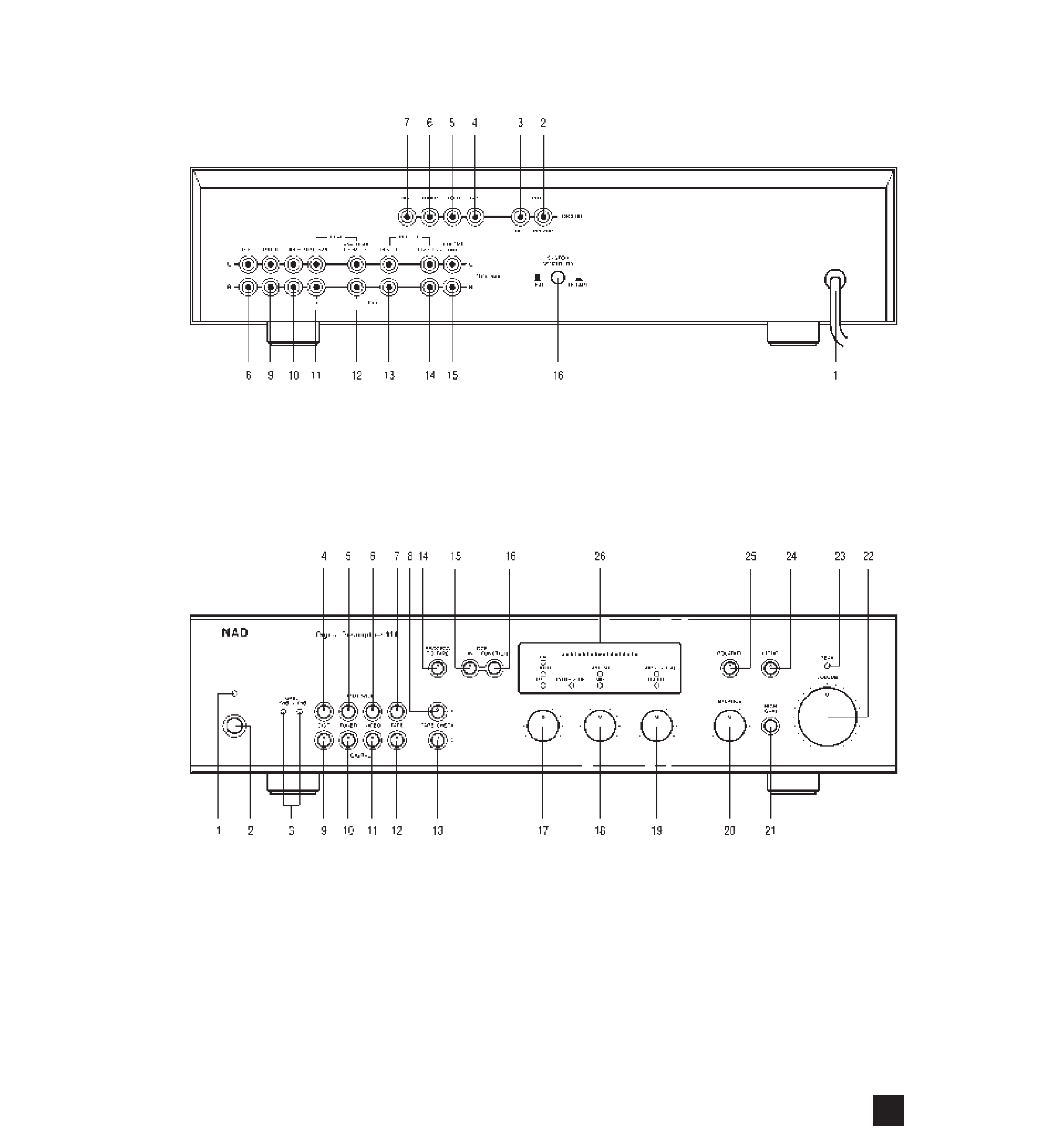
REAR PANEL CONNECTIONS - NAD 118
FRONT PANEL CONTROLS - NAD 118
NAD
3
©
1996.
118
I.M.
NAD
ELECTRONICS
LTD
©
1996.
118
I.M.
NAD
ELECTRONICS
LTD

NAD
4
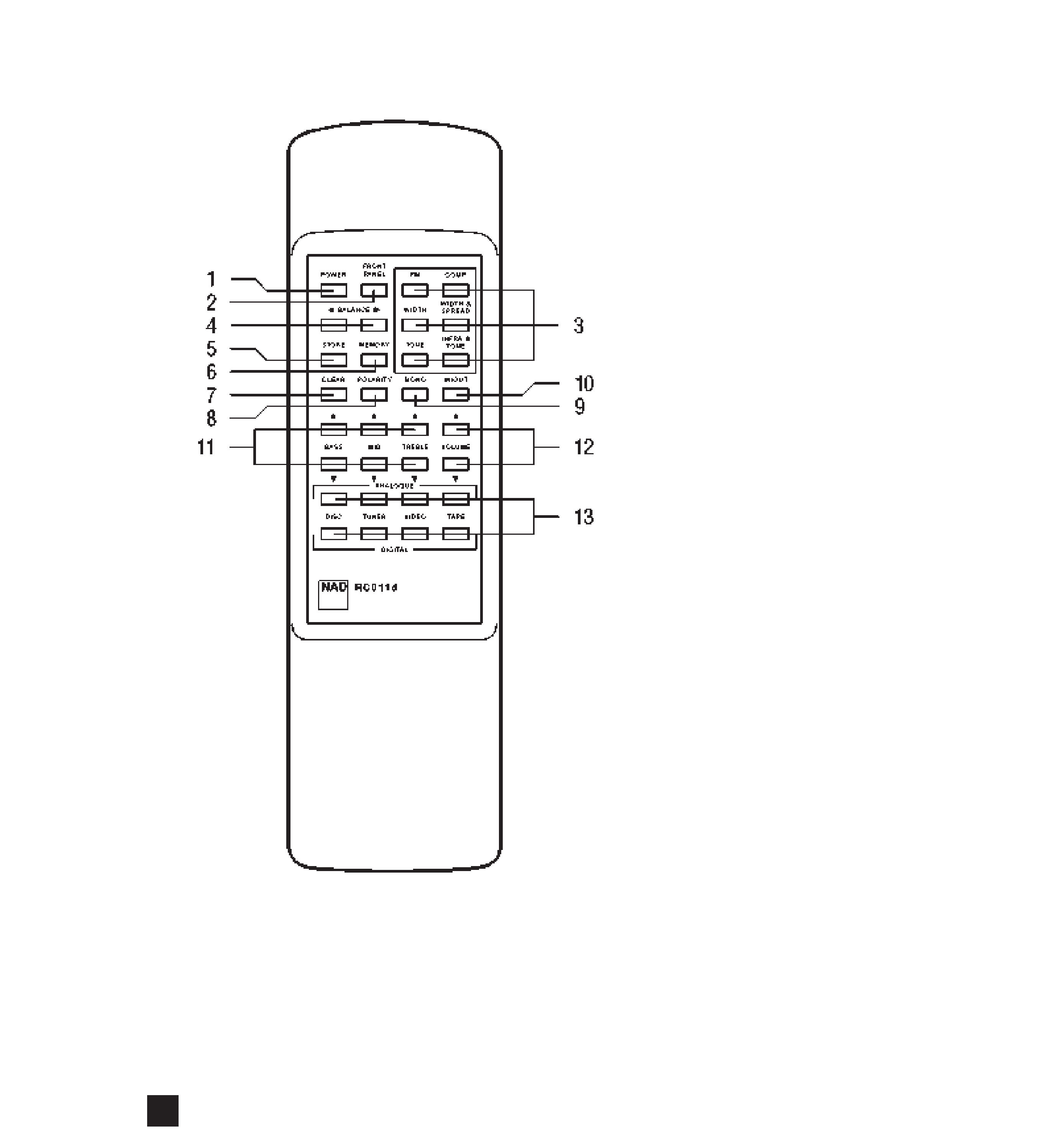
REMOTE CONTROL
©
1996.
118
I.M.
NAD
ELECTRONICS
LTD

NAD
5
GB
Thank you for purchasing the NAD Model 118 Digital pre-amplifier. The Model 118 represents the very latest in
Digital circuitry and Digital Signal Processing. Please read this manual carefully before installation and operation in
order to gain the maximum benefits of its state-of-the-art performance and possibilities.
CONTENTS
PAGE
1. INTRODUCTION. . . . . . . . . . . . . . . . . . . . . . . . . . . . . . . . . . . . . . . . . . . . . . . . 6
About digital and analogue processing and sound . . . . . . . . . . . . . . . . . . . . . . . . . . . . . . . . . . . . . . 6
2. INSTALLATION: REAR PANEL CONNECTIONS & CONTROLS . . . . . . . . . . . . . . .
6
AC Power cord . . . . . . . . . . . . . . . . . . . . . . . . . . . . . . . . . . . . . . . . . . . . . . . . . . . . . . . . . . . . . . . . . 6
Analogue source inputs and recording outputs . . . . . . . . . . . . . . . . . . . . . . . . . . . . . . . . . . . . . . . . . 6
Digital source inputs and recording output . . . . . . . . . . . . . . . . . . . . . . . . . . . . . . . . . . . . . . . . . . . . 7
Digital and analogue pre-amplifier outputs . . . . . . . . . . . . . . . . . . . . . . . . . . . . . . . . . . . . . . . . . . . . 8
3. SET-UP AND INITIALISATION. . . . . . . . . . . . . . . . . . . . . . . . . . . . . . . . . . . . . . . . . . . 8
Gain (input sensitivity) for analogue inputs . . . . . . . . . . . . . . . . . . . . . . . . . . . . . . . . . . . . . . . . . . . . 8
System Sensitivity switch
4. OPERATION INSTRUCTIONS . . . . . . . . . . . . . . . . . . . . . . . . . . . . . . . . . . . . . . . . . . . 9
Power On/Off . . . . . . . . . . . . . . . . . . . . . . . . . . . . . . . . . . . . . . . . . . . . . . . . . . . . . . . . . . . . . . . . . . . 9
Input selector . . . . . . . . . . . . . . . . . . . . . . . . . . . . . . . . . . . . . . . . . . . . . . . . . . . . . . . . . . . . . . . . . . 9
Tape Check 1 & 2 . . . . . . . . . . . . . . . . . . . . . . . . . . . . . . . . . . . . . . . . . . . . . . . . . . . . . . . . . . . . . . . 9
Volume Control
. . . . . . . . . . . . . . . . . . . . . . . . . . . . . . . . . . . . . . . . . . . . . . . . . . . . . . . . . . . . . . . 10
DSP Functions:
. . . . . . . . . . . . . . . . . . . . . . . . . . . . . . . . . . . . . . . . . . . . . . . . . . . . . . . . . . . . . . 10
Bass, Mid & Treble tone controls . . . . . . . . . . . . . . . . . . . . . . . . . . . . . . . . . . . . . . . . . . . . . . . . . . 11
Infrasonic, Mid & Treble tone controls . . . . . . . . . . . . . . . . . . . . . . . . . . . . . . . . . . . . . . . . . . . . . . 11
FM . . . . . . . . . . . . . . . . . . . . . . . . . . . . . . . . . . . . . . . . . . . . . . . . . . . . . . . . . . . . . . . . . . . . . . . . . 11
Width . . . . . . . . . . . . . . . . . . . . . . . . . . . . . . . . . . . . . . . . . . . . . . . . . . . . . . . . . . . . . . . . . . . . . . . 11
Width & Spread . . . . . . . . . . . . . . . . . . . . . . . . . . . . . . . . . . . . . . . . . . . . . . . . . . . . . . . . . . . . . . . . 12
Compression . . . . . . . . . . . . . . . . . . . . . . . . . . . . . . . . . . . . . . . . . . . . . . . . . . . . . . . . . . . . . . . . . . 12
Other features:
Balance . . . . . . . . . . . . . . . . . . . . . . . . . . . . . . . . . . . . . . . . . . . . . . . . . . . . . . . . . . . . . . . . . . . . . . 13
High Gain. . . . . . . . . . . . . . . . . . . . . . . . . . . . . . . . . . . . . . . . . . . . . . . . . . . . . . . . . . . . . . . . . . . . . 13
Mono . . . . . . . . . . . . . . . . . . . . . . . . . . . . . . . . . . . . . . . . . . . . . . . . . . . . . . . . . . . . . . . . . . . . . . . . 13
Polarity. . . . . . . . . . . . . . . . . . . . . . . . . . . . . . . . . . . . . . . . . . . . . . . . . . . . . . . . . . . . . . . . . . . . . . . 13
Making recordings; Process to Tape . . . . . . . . . . . . . . . . . . . . . . . . . . . . . . . . . . . . . . . . . . . . . . . . 13
Record Direct output . . . . . . . . . . . . . . . . . . . . . . . . . . . . . . . . . . . . . . . . . . . . . . . . . . . . . . . . . . . . 14
Record Process output . . . . . . . . . . . . . . . . . . . . . . . . . . . . . . . . . . . . . . . . . . . . . . . . . . . . . . . . . . 14
Making recordings with an analogue recorder. . . . . . . . . . . . . . . . . . . . . . . . . . . . . . . . . . . . . . . . . 14
Making recordings with a digital recorder . . . . . . . . . . . . . . . . . . . . . . . . . . . . . . . . . . . . . . . . . . . . 14
Making copies from an analogue recorder to a digital recorder . . . . . . . . . . . . . . . . . . . . . . . . . . . 14
Making copies from a digital recorder to an analogue recorder . . . . . . . . . . . . . . . . . . . . . . . . . . . 15
5. REMOTE CONTROL. . . . . . . . . . . . . . . . . . . . . . . . . . . . . . . . . . . . . . . . . . . . . . . . . . 15
Inserting batteries . . . . . . . . . . . . . . . . . . . . . . . . . . . . . . . . . . . . . . . . . . . . . . . . . . . . . . . . . . . . . . 15
Front Panel button . . . . . . . . . . . . . . . . . . . . . . . . . . . . . . . . . . . . . . . . . . . . . . . . . . . . . . . . . . . . . . 15
Clear button . . . . . . . . . . . . . . . . . . . . . . . . . . . . . . . . . . . . . . . . . . . . . . . . . . . . . . . . . . . . . . . . . . . 15
Memory Banks; Store & Memory buttons . . . . . . . . . . . . . . . . . . . . . . . . . . . . . . . . . . . . . . . . . . . . 15
6. ADVANCED OPERATION INSTRUCTIONS . . . . . . . . . . . . . . . . . . . . . . . . . . . . . . . 16
Dither & Digital Record Output. . . . . . . . . . . . . . . . . . . . . . . . . . . . . . . . . . . . . . . . . . . . . . . . . . . . . 16
Factory default settings & Special functions . . . . . . . . . . . . . . . . . . . . . . . . . . . . . . . . . . . . . . . . . . 16
Changing sampling frequency of ADC. . . . . . . . . . . . . . . . . . . . . . . . . . . . . . . . . . . . . . . . . . . . . . . 17
Enabling / disabling Digital Pre-Out . . . . . . . . . . . . . . . . . . . . . . . . . . . . . . . . . . . . . . . . . . . . . . . . . 17
Enabling / disabling Volume Control . . . . . . . . . . . . . . . . . . . . . . . . . . . . . . . . . . . . . . . . . . . . . . . . 17
Clear Memory (EEPROM); return to default settings. . . . . . . . . . . . . . . . . . . . . . . . . . . . . . . . . . . . 17
Enabling / disabling Dither On/Off tape output . . . . . . . . . . . . . . . . . . . . . . . . . . . . . . . . . . . . . . . . 17
7. GLOSSARY. . . . . . . . . . . . . . . . . . . . . . . . . . . . . . . . . . . . . . . . . . . . . . . . . . . . . . . . . 18
TROUBLE SHOOTING GUIDE . . . . . . . . . . . . . . . . . . . . . . . . . . . . . . . . . . . . . . . . . . . . . 19
NAD 118 DIGITAL PREAMPLIFIER
