GB
F
D
E
I
P
S
NAD
114
· OWNER'S MANUAL
· MANUEL D'INSTALLATION
· BEDIENUNGSANLEITUNG
· MANUAL DEL USUARIO
· MANUALE DELLE ISTRUZIONI
· MANUAL DO PROPRIETÁRIO
· BRUKSANVISNING
Warning: To reduce the risk of fire or electric shock, do not expose this
unit to rain or moisture.
The graphic symbol of a lightning flash with an arrow point within a trian-
gle signifies that there is dangerous voltage within the unit and it
poses a hazard to anyone removing the cover to gain access to the
interior of the unit. Only qualified service personnel should
make any such attempt.
The graphic symbol of an exclamation point within an equilateral trian-
gle warns a user of the device that it is necessary to refer to the
instruction manual and its warnings for proper operation of the unit.
Do not place this unit on an unstable cart, stand or tripod,
bracket or table. The unit may fall, causing serious injury to a
child or adult and serious damage to the unit. Use only with a
cart, stand, tripod, bracket or table recommended by the man-
ufacturer or sold with the unit. Any mounting of the device on a
wall or ceiling should follow the maufacturer's instructions and
should use a mounting accessory recommended by the manu-
facturer.
An appliance and cart combination should be moved with care. Quick stops,
excessive force and uneven surfaces may cause the appliance and cart combi-
nation to overturn.
Read and follow all the safety and operating instructions before connecting or
using this unit. Retain this notice and the owner's manual for future reference.
All warnings on the unit and in it's operating instructions should be adhered to.
Do not use this unit near water; for example, near a bath tub, washbowl, kitchen
sink, laundry tub, in a wet basement or near a swimming pool.
The unit should be installed so that its location or position does not interfere with
its proper ventilation. For example, it should not be situated on a bed, sofa, rug
or similar surface that may block the ventilation openings; or placed in a built-in
installation, such as a bookcase or cabinet, that may impede the flow of air
through its ventilation openings.
The unit should be situated from heat sources such as radiators, heat registers,
stoves or other devices (including amplifiers) that produce heat.
The unit should be connected to a power supply outlet only of the voltage and
frequency marked on its rear panel.
The power supply cord should be routed so that it is not likely to be walked on or
pinched, especially near the plug, convenience receptacles, or where the cord
exits from the unit.
Unplug the unit from the wall outlet before cleaning. Never use benzine, thinner
or other solvents for cleaning. Use only a soft damp cloth.
The power supply cord of the unit should be unplugged from the wall outlet when
it is to be unused for a long period of time.
Care should be taken so that objects do not fall, and liquids are not spilled into
the enclosure through any openings.
This unit should be serviced by qualified service personnel when:
A. The power cord or the plug has been damaged; or
B. Objects have fallen, or liquid has been spilled into the unit; or
C. The unit has been exposed to rain or liquids of any kind; or
D. The unit does not appear to operate normally or exhibits a marked change in
performance; or
E. The device has been dropped or the enclosure damaged.
DO NOT ATTEMPT SERVICING OF THIS UNIT YOURSELF.
REFER SERVICING TO QUALIFIED SERVICE
PERSONNEL.
Upon completion of any servicing or repairs, request the service shop's assur-
ance that only Factory Authorized Replacement Parts with the same characteris-
tics as the original parts have been used, and that the routine safety checks
have been performed to guarantee that the equipment is in safe operating condi-
tion.
REPLACEMENT WITH UNAUTHORIZED PARTS MAY RESULT IN FIRE,
ELECTRIC SHOCK OR OTHER HAZARDS.
ATTENTION
POUR EVOTER LES CHOC ELECTRIQUES, INTRODUIRE LA LAME
LA PLUS LARGE DE LA FICHE DANS LA BORNE CORRESPON-
DANTE DE LA PRISE ET POUSSER JUSQU'AU FOND.
CAUTION
TO PREVENT ELECTRIC SHOCK MATCH WIDE BLADE OF PLUG
TO WIDE SLOT FULL INSERT.
If an indoor antenna is used (either built into the set or installed separately),
never allow any part of the antenna to touch the metal parts of other electrical
appliances such as a lamp, TV set etc.
CAUTION
POWER LINES
Any outdoor antenna must be located away from all power lines.
OUTDOOR ANTENNA GROUNDING
If an outside antenna is connected to your tuner or tuner-preamplifier, be sure
the antenna system is grounded so as to provide some protection against volt-
age surges and built-up static charges. Section 810 of the National Electrical
Code, ANSI/NFPA No. 70-1984, provides information with respect to proper
grounding of the mast and supporting structure, grounding of the lead-in wire to
an antenna discharge unit, size of grounding conductors, location of antenna dis-
charge unit, connection to grounding electrodes and requirements for the
grounding electrode.
a. Use No. 10 AWG (5.3mm2) copper, No. 8 AWG (8.4mm2) aluminium, No. 17
AWG (1.0mm2) copper-clad steel or bronze wire, or larger, as a ground wire.
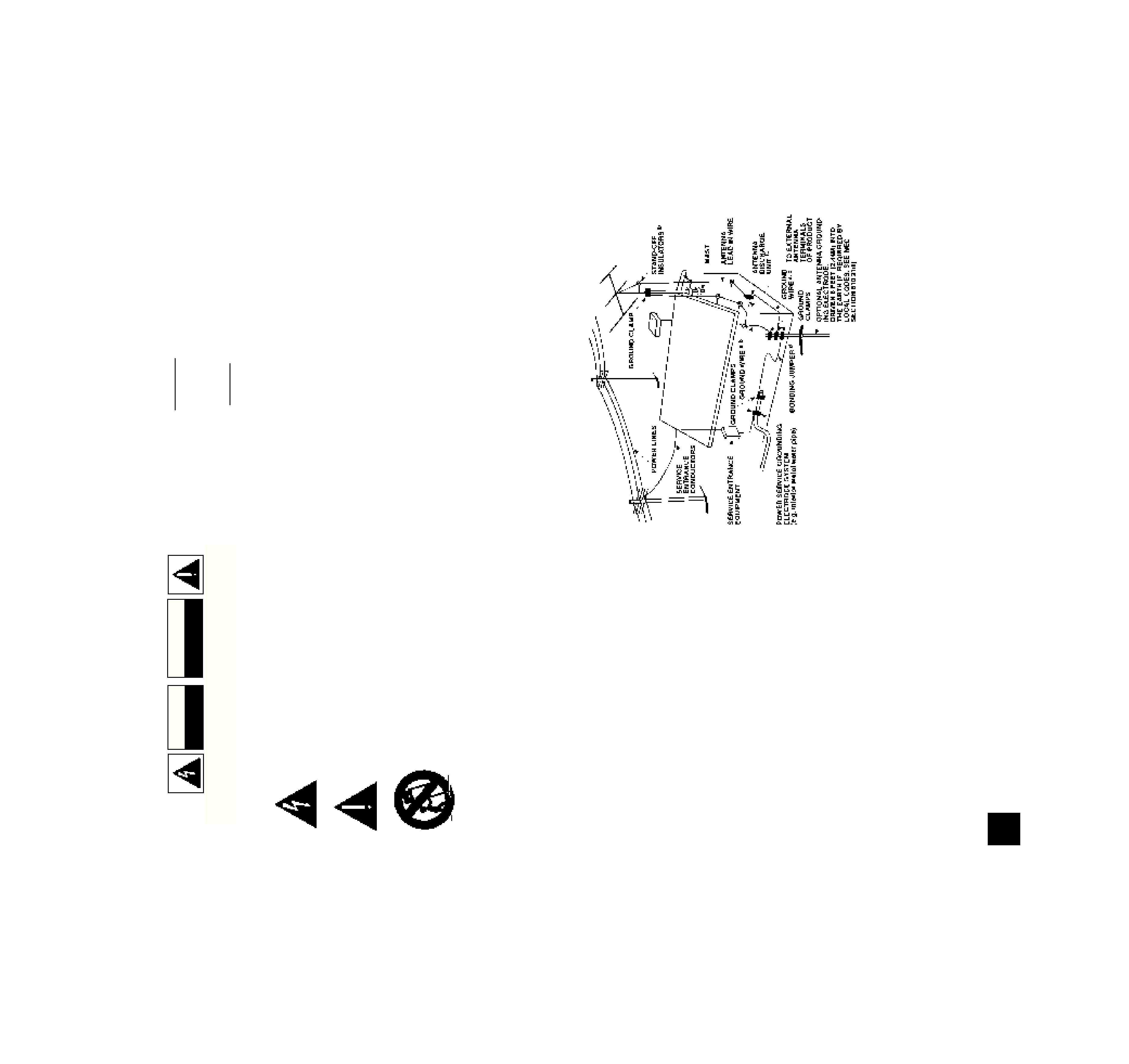
b. Secure antenna lead-in and ground wires to house with stand-off insulators
spaced from 4-6 feet (1.22 - 1.83 m) apart.
c. Mount antenna discharge unit as close as possible to where lead-in enters
house.
d. Use jumper wire not smaller than No.6 AWG (13.3mm2) copper, or the equiva-
lent, when a separate antenna-grounding electrode is used. see NEC Section
810-21 (j).
EXAMPLE OF ANTENNA GROUNDING AS PER NATIONAL ELECTRICAL
CODE INSTRUCTIONS CONTAINED IN ARTICLE 810 - RADIO AND TELEVI-
SION EQUIPMENT.
NOTE TO CATV SYSTEM INSTALLER: This reminder is provided to
call the CATV system installer's attention to Article 820-22 of the
National Electrical Code that provides guidelines for proper grounding
and, in particular, specifies that the ground cable ground shall be con-
nected to the grounding system of the building, as close to the point of
cable entry as practical.
NAD
2
CAUTION
RISK OF ELECTRIC
SHOCK DO NOT OPEN
ATTENTION:
RISQUE DE CHOC ELECTRIQUE
NE PAS OUVRIR
CAUTION: TO REDUCE THE RISK OF ELECTRIC SHOCK, DO NOT REMOVE COVER (OR BACK).
ATTENTION: AFIN DEVITER UN CHOC ELECTRIQUE, ET LES CONSEQUENCES GRAVES QUI
POURRAIENT EN RESULTER, TENTEZ PAS D'OUVRIR L'APPAREIL ET DE TOUCHER AUX
COMPOSANTS INTERNES SANS LA PRESENCE D'UNE SERVICE PERSONNEL.
THE FOLLOWING PRECAUTIONS AND SAFETY INSTRUCTIONS
ARE REQUIREMENTS OF UL AND CSA SAFETY REGULATIONS
NAD
3
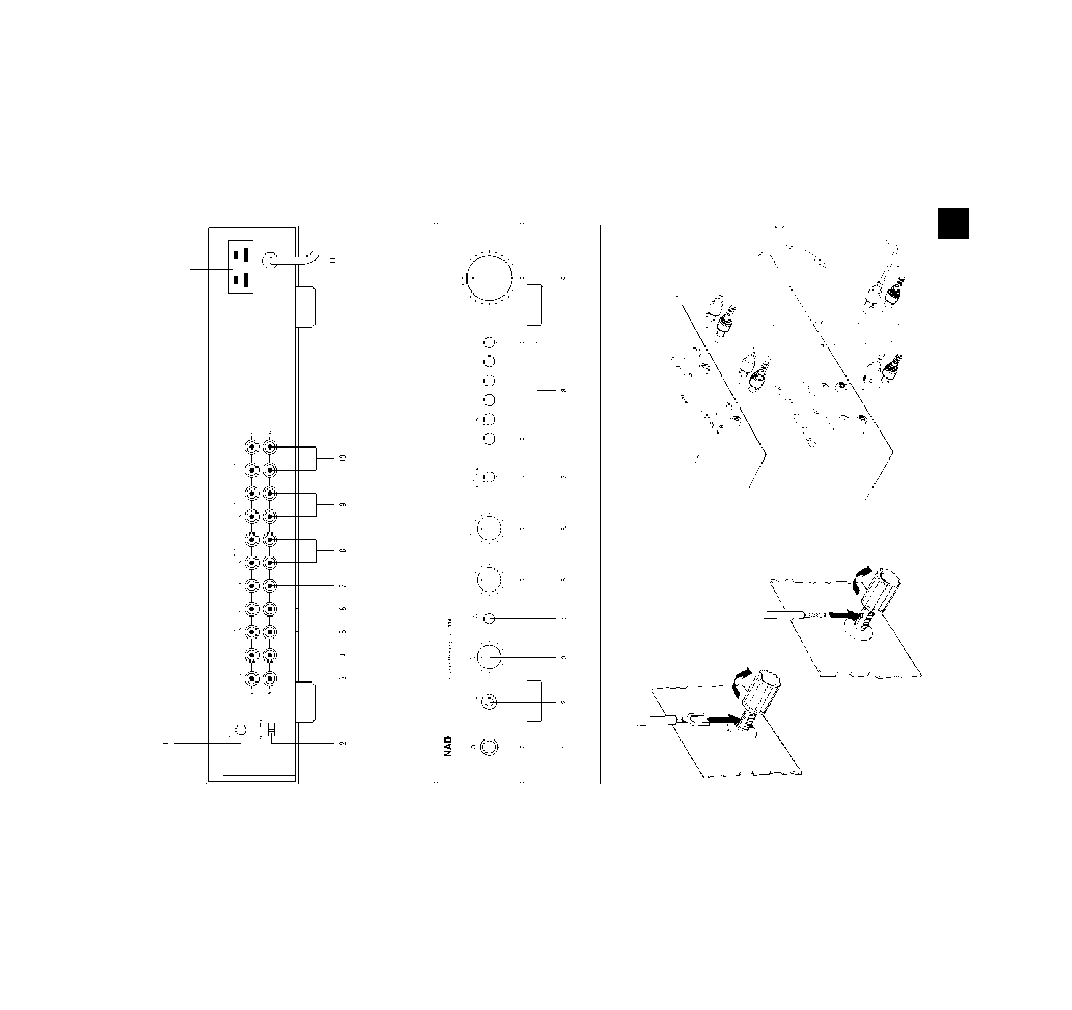
REAR PANEL CONNECTIONS
FIGURE 1.
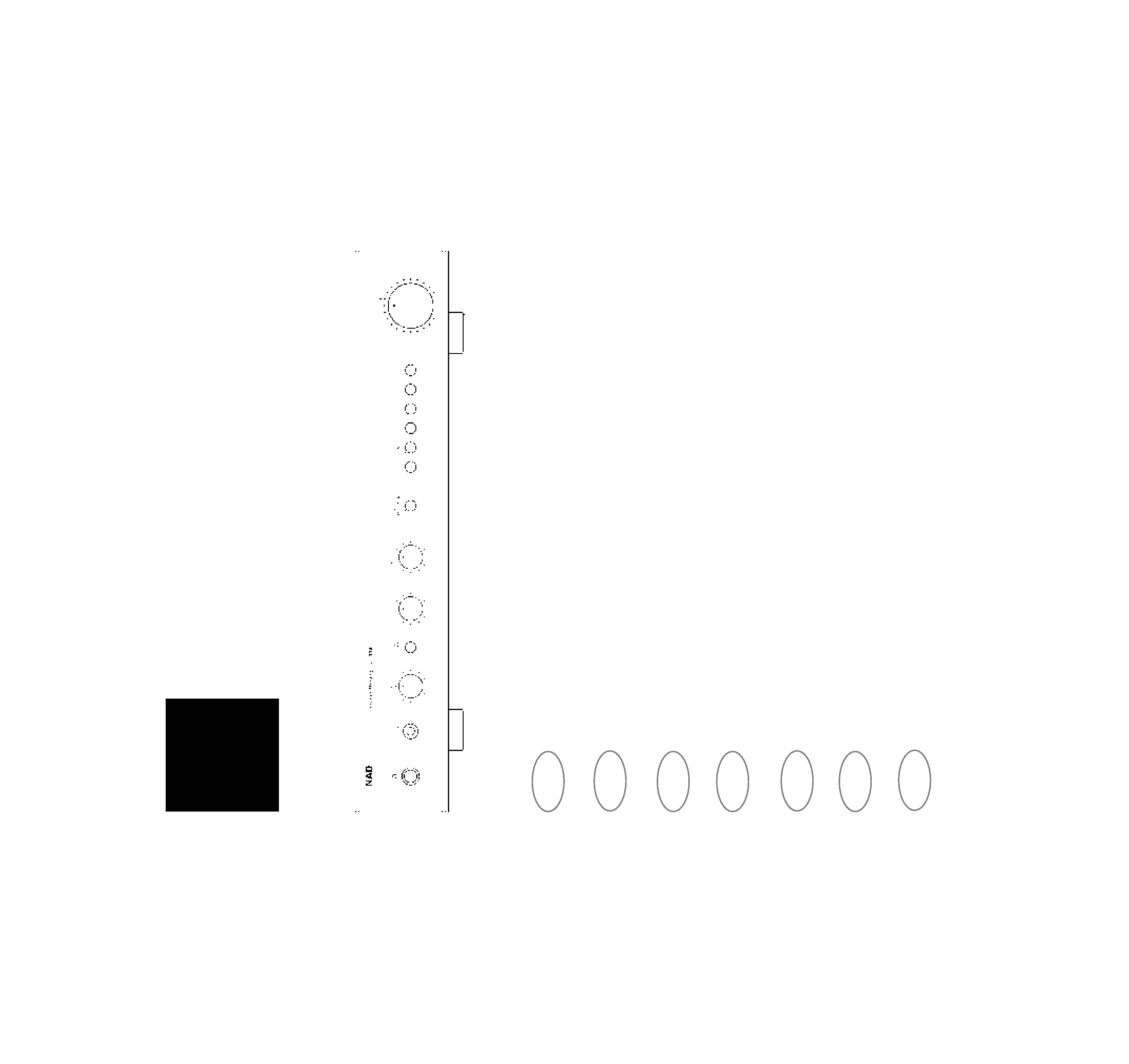
FIGURE 2.
FRONT PANEL CONTROLS
120V version only

INSTRUCTIONS FOR INSTALLATION
AND OPERATION
Your NAD114 should be placed on a firm, level
surface. Avoid placing the unit in direct sunlight, near
sources of heat and damp or in poorly ventilated posi-
tions.
If the unit is not going to be used for some time,
disconnect the plug from the AC socket.
Should water get into your NAD 114, shut off the
power to the unit and remove the plug from the AC
socket. Have the unit inspected by a qualified service
technician before attempting to use it again.
Do not remove the cover, there are no user-ser-
viceable parts inside.
Use a dry soft cloth to clean the unit. If necessary,
lightly dampen the cloth with soapy water. Do not use
solutions containing benzol or other volatile agents.
REAR PANEL CONNECTIONS
1. PHONO GROUND.
If your LP turntable is equipped with a grounding
wire (usually a green wire terminating in a U-shaped
spade lug), connect it to this terminal. Turn the
thumb-nut counter-clockwise, place the spade lug
under the nut, and tighten the thumb-nut clockwise to
secure the lug. If the grounding wire has no spade
lug, strip off 1 cm of insulation to expose the bare
wire, twist the wire strands tightly together, insert the
wire though the small hole in the shaft of the Ground
terminal, and tighten the thumb-nut to fasten the wire
in place. (Fig. 1).
If you encounter a persistent low-level hum or buzz
in the sound, connect a wire from the Ground termi-
nal to a true earth-ground, i.e. a copper-plated rod
driven several feet into the earth. A substitute electri-
cal ground, such as a cold water pipe, may also
prove effective.
2. MM/MC SELECTOR.
This switch sets the input sensitivity and gain of the
phono preamplifier circuit. Set it according to the out-
put level of your phono pickup cartridge. Set the
switch at MM for cartridges of the moving magnet,
induced magnet, moving flux, and moving iron (vari-
able reluctance) types, and for "high-output" moving-
coil pickups, i.e. those with a rated output of 1.0 mV
or greater. If your cartridge is a low-output moving-
coil pickup (with a rated output of less than 1.0 mV),
set the switch at MC.
Here is another way to determine the preferred set-
ting of the MM/MC switch. Begin by setting it to MM.
After you have completed the installation and wiring
of the system, play a record. You should obtain a
satisfyingly loud volume level with VOLUME control
set at 9 o'clock. If you have to turn up the VOLUME
control beyond 9 o'clock to get adequately loud
sound, turn the VOLUME back down and re-set the
MM/MC switch to MC.
3. PHONO INPUT.
Plug the signal cables from your turntable into
these jacks. If the cables or plugs are color-coded,
refer to your turntable's instruction manual to learn
which cable or plug is for the Left channel (upper
jack) and which for the Right (lower jack). Be careful
to insert each plug fully into the socket so that the
plug's metal skirt fits tightly over the exterior of the
socket. If necessary, crimp the plug's metal skirt
slightly so as to obtain a tight fit with the socket.
4. CD INPUT.
Connect the audio signal cables from a digital
Compact Disc player to these jacks. The input signal
will be fed to the Volume control before reaching any
active circuitry, so the preamplifier's circuits cannot
be overloaded by high-level signals from the digital
player.
If you don't have a CD player, any other line-level
signal source (such as a spare tape deck) may be
connected to the CD input.
5. VIDEO SOUND INPUT.
Connect a video-related audio signal here, such as
the audio output from a video cassette recorder,
video disc player, TV monitor/receiver, or stereo tele-
vision decoder. Alternatively, any "line-level" audio
signal may be connected here, such as the playback
from a spare tape deck.
If you don't have a VCR player, any other line-level
signal source (such as a spare tape deck) may be
connected to the Video Sound input.
6. AUXILIARY INPUT
Any "line-level"signal source may be connected
here, such as the audio output from a spare deck or
video product. For example. you could connect the
audio from a stereo television set here and the audio
from a stereo VCR to the Video input.
7. TUNER INPUT
Connect the audio signal cable from an AM/FM (or
video) tuner to this pair of jacks.
If you don't have a Tuner, any other line-level sig-
nal source (such as a spare tape deck) may be con-
nected to the Tuner input.
8. TAPE 1 INPUT/OUTPUT.
These jacks allow you to connect a second tape
recorder of any type, and the preamplifier is wired to
permit copying tapes from one recorder to the other.
Connect a cable from the TAPE 1 OUT jacks of the
114 to the recorder's LINE IN jacks, and another
cable from the recorder's LINE OUT jacks to the
TAPE 1 IN jacks.
The TAPE 1 jacks may be used for a signal-pro-
cessing accessory instead of a second tape recorder.
Examples of such accessories include a dynamic
range processor, a dynamic noise filter, or a graphic
equalizer. Connect a patch cord from the TAPE 1
OUT jacks to the processor's inputs, and another
NAD
4
GB
NAD 114 STEREO PREAMPLIFIER

GB
patch cord from processor's outputs to the TAPE 1 IN
jacks.
The tape connections may be used with recorders
of all types: cassette, micro-cassette, open-reel, digi-
tal, etc. To make recordings, connect a stereo patch
cord from the TAPE 1 OUT jacks of the 114 to the
recorder's LINE IN jacks (not its microphone inputs).
To play back tapes, connect a stereo patch cord from
the recorder's LINE OUT jacks to the TAPE 1 IN
jacks of the 114. (See Figure 2)
9. TAPE 2 INPUT/OUTPUT.
These jacks allow you to connect a second tape
recorder of any type, and the preamplifier is wired to
permit copying tapes from one recorder to the other.
Connect a cable from the TAPE 2 OUT jacks of the
114 to the recorder's LINE IN jacks, and another
cable from the recorder's LINE OUT jacks to the
TAPE 2 IN jacks.
10. PRE OUT 1 & 2.
Two pairs of RCA phono preamp output jacks are
provided for convenience. This is the normal output
from the preamplifier. Connect a stereo signal cable
from these jacks to the main input jacks on your
power amplifier.
The preamp has a low output impedance (220
ohms). It can drive several amplifiers connected in
parallel, and it can be used with long signal cables in
order to drive power amplifiers that are located near
the speakers (or "powered" speakers having built-in
power amplifiers).
If you have a special loudspeaker equalizer or
another signal processor that should be installed in
the signal path after the volume control, connect a
cable from either pair of the PRE OUT jacks to the
input of the processor, and a second cable from the
output of the processor to the main input of your
power amplifier.
11. AC LINE CORD.
After you complete all connections to the preampli-
fier, plug the AC line cord into a "live" AC socket.
FRONT PANEL CONTROLS
1. POWER
Press to switch on the power to the 114 (and to any
other products plugged into the SWITCHED conve-
nience outlets on the rear panel of 120V versions) .
To switch the power off, press the button again.
2. PHONES
Plug stereo headphones in here. The circuit will
provide proper drive signals for all conventional
stereo headphones regardless of their impedance,
with just one exception: electrostatic headphones
usually are supplied with an adapter unit which must
be connected directly to the speaker terminals on
your power amplifier.
Insertion of a plug into the PHONES socket auto-
matically mutes the signal at the PREAMP OUTPUT
jacks, silencing the loudspeakers. In order to resume
listening to loudspeakers you must unplug the head-
phones from the PHONES socket.
3. BASS.
The Bass control adjusts the relative level of the
low frequencies in the sound.
The electrical
response of the preamplifier is flattest when the con-
trol is set in the detent at the 12 o'clock position.
Rotation of the knob to the right (clockwise) increases
the level of low-frequency sounds, and rotation
counter-clockwise decreases their level. Adjust the
Bass control to achieve the tonal balance that sounds
most natural to you.
At moderate rotations away from center the effect
of the Bass control is subtle, because its action is
confined to the lowest audible frequencies where sig-
nificant energy is seldom found in recordings. Only at
large rotations away from center is there a substantial
boost or cut at the mid-bass frequencies that are
common in music.
When the TONE DEFEAT button is engaged, the
Bass and treble circuits are bypassed.
4. TONE DEFEAT.
When this button is pressed the Bass and Treble
circuits are bypassed, restoring precisely flat frequen-
cy response. This provides a convenient way to eval-
uate settings of the Bass and Treble controls. By
adjusting the tone controls and then switching them in
and out of the signal path, you can easily evaluate
their effect on the musical sound.
5. TREBLE.
The Treble control adjusts the relative level of the
high frequencies in the sound. The response of the
preamplifier is flattest when the control is set in the
detent at the 12 o'clock position. Rotation of the
Treble control to the right (clockwise) increases the
level of high-frequency sounds, and rotation counter-
clockwise decreases their level. Adjust the Treble
control to achieve the tonal balance that sounds most
natural to you.
Boosting the Treble increases the brilliance and
clarity of details in the sound, but also makes any
noise more prominent. Turning down the Treble
makes the sound mellower while suppressing hiss
and record surface noise; but too much Treble roll-off
will make the sound dull.
6. BALANCE.
The Balance control adjusts the relative levels of
the left and right channels. It has no effect on record-
ings being made. A detent at the 12 o'clock position
marks the point of equal balance. Rotation of the
Balance control to the right (clockwise) decreases the
level of the left channel so that only the right channel
is heard, thus shifting the sonic image to the right.
Rotation of the control to the left shifts the sonic
image toward the left speaker.
NAD
5