CAUTION:
Before servicing this chassis, it is important that the service person read the "SAFETY PRECAUTIONS" and
"PRODUCT SAFETY NOTICE" contained in this manual.
· Weight and dimensions shown are approximate.
· Design specifications are subject to change without notice.
MITSUBISHI DIGITAL ELECTRONICS AMERICA, INC.
9351 Jeronimo Road, Irvine, CA 92618-1904
Copyright © 2001 Mitsubishi Digital Electronics America, Inc.
All Rights Reserved
MITSUBISHIELECTRIC Ser
Ser
Ser
Ser
Service
vice
vice
vice
vice
Manual
Manual
Manual
Manual
Manual
2001
2001
2001
2001
2001
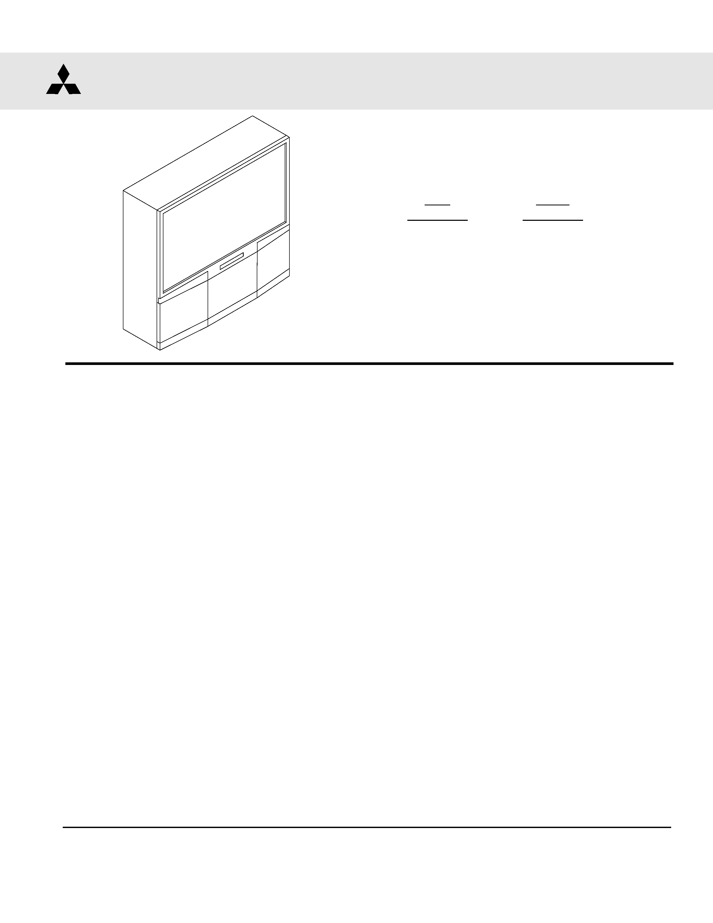
PROJECTION TELEVISION
V18 / V18+ CHASSIS
SPECIFICATIONS
· Power Input
: AC 120V, 60Hz
· Power
: 280W
Consumption
· Frequency
: VHF
54 ~ 470MHz
Range
UHF 470 ~ 806MHz
· Antenna Input
: VHF/UHF 75
unbalanced
Single axis input
·
CRT Size
: [7 inches]
·
High Voltage
: 32.0kV (at 0A)
·
Speaker
: [WT-46809 / WS-55809 / WS-65809
5" round type, full range 2 pcs. (8
10W)
: [WS-55819 / WS-65819 / WS-73907]
6" round type, full range 2 pcs. (8
10W)
·
Weight
: [WT-46809] 170 lbs
: [WS-55809] 250 lbs
: [WS-55819] 244.5 lbs
: [WS-65809] 323 lbs
: [WS-65819] 323 lbs
·
Cabinet
: [Model] (H)x(W)x(D)
Dimensions
: [WT-46809] 38.4"x42.8"x27.1"
: [WS-55809] 50"x50.6"x26.3"
: [WS-55819] 50.4"x50.6"x26.4"
: [WS-65809] 61.8"x58.7"x28.1"
: [WS-65819] 61.8"x58.8"x28.1"
·
Input Level
: VIDEO IN JACK (RCA Type)
1.0Vp-p 75
unbalanced
: AUDIO IN JACK (RCA Type)
-4.7dBm 43k
unbalanced
: S-VIDEO IN JACK
(Y/C separate type)
Y:1.0 Vp-p C:0.286Vp-p(BURST)
75
unbalanced
: DVD / Y, Cr, Cb (RCA Type)
Y: 1.0 Vp-p Cr, Cb: 700mVp-p
: ATV / Y(G), Pr(R), Pb(B), H, V
Y: 1.0Vp-p with sync 75
(BNC)
Pr, Pb: 700mV 75
H, V: 3.0Vp-p 75
·
Output Level
: VIDEO OUT JACK (RCA Type)
1.0Vp-p 75
unbalanced
: AUDIO OUT JACK (RCA Type)
-4.7dBm 4.7k
unbalanced
V18
MODELS
WT-46809
WS-55809
WS-65809
V18+
MODELS
WS-55819
WS-65819
WS-55809


MODELS: WT-46809 / WS-55809 / WS-55819 / WS-65809 / WS-65819
Page 3
INTRODUCTION ................................................................................................................................5
PRODUCT SAFETY NOTICE ............................................................................................................. 5
SAFETY PRECAUTIONS ................................................................................................................... 6
DISASSEMBLY
Cabinet Disassembly (Front View) .............................................................................................. 7
WT-46809 .............................................................................................................................. 7
WS-55809 / WS-65809 .......................................................................................................... 8
WS-55819 / WS-65819 .......................................................................................................... 9
Cabinet Disassembly (Rear View) ............................................................................................. 10
WT-46809 ............................................................................................................................ 10
WS-55809 / WS-55819 / WS-65809 / WS-65819 ................................................................. 11
SERVICING THE LENTICULAR SCREEN AND FRESNEL LENS
Lenticular Screen and Fresnel Lens Removal ......................................................................... 12
WT-46809 / WS-55809 / WS-65809 ..................................................................................... 12
WS-55819 / WS-65819 ........................................................................................................ 13
Lenticular Screen and Fresnel Lens Installation .................................................................... 14
SERVICING THE DIAMONDSHIELDSTM r
DiamondShield TM Removal & Installation ...................................................................................... 15
SERVICING PCBs
Chassis Removal .......................................................................................................................... 16
PCB Locations .............................................................................................................................. 16
Main Components Location ........................................................................................................... 16
CRT REPLACEMENT
CRT Removal ................................................................................................................................17
CRT Installation ............................................................................................................................ 18
ELECTRICAL ADJUSTMENTS
Test Equipment ............................................................................................................................. 20
Initial Setup ................................................................................................................................... 21
LED Indicator Diagnostics ............................................................................................................. 22
Circuit Adjustment Mode ............................................................................................................... 22
Convergence Adjustment Mode ..................................................................................................... 24
E2PROM Replacement ................................................................................................................. 27
Adjustment Items List ................................................................................................................... 27
Adjustment Test Points ................................................................................................................. 30
Adjustment Procedures ................................................................................................................ 31
Audio Circuit ........................................................................................................................ 31
High Voltage Regulation ....................................................................................................... 32
Main/Sub Y Level ................................................................................................................. 32
Side by Side Sub Picture Tint .............................................................................................. 33
Side by Side Sub Picture Color ............................................................................................ 33
CRT Cutoff ........................................................................................................................... 34
White Balance (NTSC) ......................................................................................................... 34
White Balance (HD) ............................................................................................................. 35
Cb, Cr Offset ........................................................................................................................ 35
Black Level .......................................................................................................................... 36
Sub Contrast ....................................................................................................................... 36
CONTENTS

MODELS: WT-46809 / WS-55809 / WS-55819 / WS-65809 / WS-65819
Page 4
Dynamic Focus Preset ........................................................................................................ 37
Electrostatic Focus & Alignment Magnet Adjustment .......................................................... 37
Lens Focus .......................................................................................................................... 38
Character Position ............................................................................................................... 38
Deflection/Convergence Geometry Presets .......................................................................... 39
Deflection Circuit Geometry Adjustments ............................................................................. 40
Convergence Circuit Geometry Adjustments ........................................................................ 41
Centering and Static Convergence ....................................................................................... 42
Coarse Convergence Adjustments ....................................................................................... 43
Fine Convergence Adjustments ............................................................................................ 44
CHIP PARTS REPLACEMENT ......................................................................................................... 45
REPLACEMENT PARTS
Parts Ordering .............................................................................................................................. 46
Critical and Warranty Parts Designation ........................................................................................ 46
Parts Tolerance Codes .................................................................................................................. 46
Quick Reference List .................................................................................................................... 47
Service Parts List .......................................................................................................................... 48
Screen Parts List .......................................................................................................................... 58
CIRCUITRY BLOCK DIAGRAMS
Standby Supplies Regulator .......................................................................................................... 60
Switched Supplies Regulator ........................................................................................................ 61
Video / Color A/V Switch Circuit ................................................................................................... 62
Video / Color Signal Path .............................................................................................................. 63
Sync Signal Path .......................................................................................................................... 64
Deflection / HV .............................................................................................................................. 65
X-Ray Protect ............................................................................................................................... 65
Sound Circuit ................................................................................................................................ 66
Convergence ................................................................................................................................. 67
Control Circuitry ............................................................................................................................ 68
Section 2 .... Schematic Diagrams
SCHEMATIC DIAGRAMS
Overall Block Diagram ................................................................................................................... 1
PCB-MAIN ..................................................................................................................................... 2
PCB-POWER ................................................................................................................................. 3
PCB-TERMINAL ............................................................................................................................ 4
PCB-SIGNAL-1 (AV I/O) .................................................................................................................. 5
PCB-SIGNAL-2 (MICRO) ................................................................................................................. 6
PCB-SIGNAL-3 (VC / SW) .............................................................................................................. 7
PCB-3DYC ..................................................................................................................................... 8
PCBs-CONV GEN / JUNGLE ..........................................................................................................9
PCBs - CRT / CONTROL / AI / SVM / DBF ................................................................................... 10
PCB-2HDW-1 ............................................................................................................................... 11
PCB-2HDW-2) .............................................................................................................................. 12
PCB-2HDW-3 ............................................................................................................................... 13
PCB LAYOUT DIAGRAMS ............................................................................................................... 14

Page 5
MODELS: WT-46809 / WS-55809 / WS-55819 / WS-65809 / WS-65819
INTRODUCTION
This service manual provides service instructions for PTV Models WT-46809, WS-55809 and WS-65809 which use
the V18 chassis, and PTV Models WS-55819, and WS-65819 which use the V18+ chassis. Service personnel should
read this manual thoroughly before servicing these chassis.
This service manual includes:
1. Assembly and disassembly instructions for the front and rear cabinet components.
2. Servicing of the Lenticular Screen and Fresnel Lens.
3. Servicing printed circuit boards (PCBs).
4. CRT replacement procedure.
5. Electrical adjustments.
6. Chip parts replacement procedures.
7. Circuit path diagrams.
The parts list section of this service manual includes:
1. Cabinet and screen parts.
2. Electrical parts.
Schematic and block diagrams of the above listed models are included in this service manual for better under-
standing of the circuitry. PCB drawings are also included for easy location of parts and test points.
PRODUCT SAFETY NOTICE
Many electrical and mechanical parts in television receivers have special safety related characteristics. These
characteristics are often not evident from visual inspection nor can the protection afforded by them necessarily be
obtained by using replacement components rated for higher voltage, wattage, etc.
Replacement parts which have special safety characteristics are identified in this service manual.
Electrical components having such features are identified by shading
on the schematic diagram and by bold
type in the parts list of this service manual. The replacement for any safety part should be identical in value
and characteristics.