1
MITSUBISHI HS-S5600E
Electrical Adjustments
Circuit adjustments become necessary, in most
cases due to the wear of mechanical parts or
following the replacement of critical components
such as the video head. Certain circuit defects
can often cause circuit adjustments to vary
considerably. Should this occur, be sure to
determine the nature of the defect and repair
prior to proceeding with adjustments.
Always use the test equipment recommended
for a given adjustment procedure. If the
appropriate test equipment is not available, it is
recommended that adjustments NOT be
attempted. Refrain from the indiscreet adjust-
ment of circuit adjustment controls unless
properly equipped to do so.
SERVO CIRCUIT
1. PB SWITCHING POINT
MODE
Playback
Alignment tape
(Grey scale)
ADJ. METHOD
Oscilloscope to TP2J(SIGNAL)
Oscilloscope's EXT trigger to TP4B (CONTROL)
EXT trigger (--) VR4A0 (CONTROL)
DIV 20mV
TIM 50
µSec
(10:1)
ADJUSTMENT PROCEDURE
1. Set the VIDEO switch (S705) to "B/W".
2. Set the NORMAL TRACKING control(VR702)
to centre click stop position.
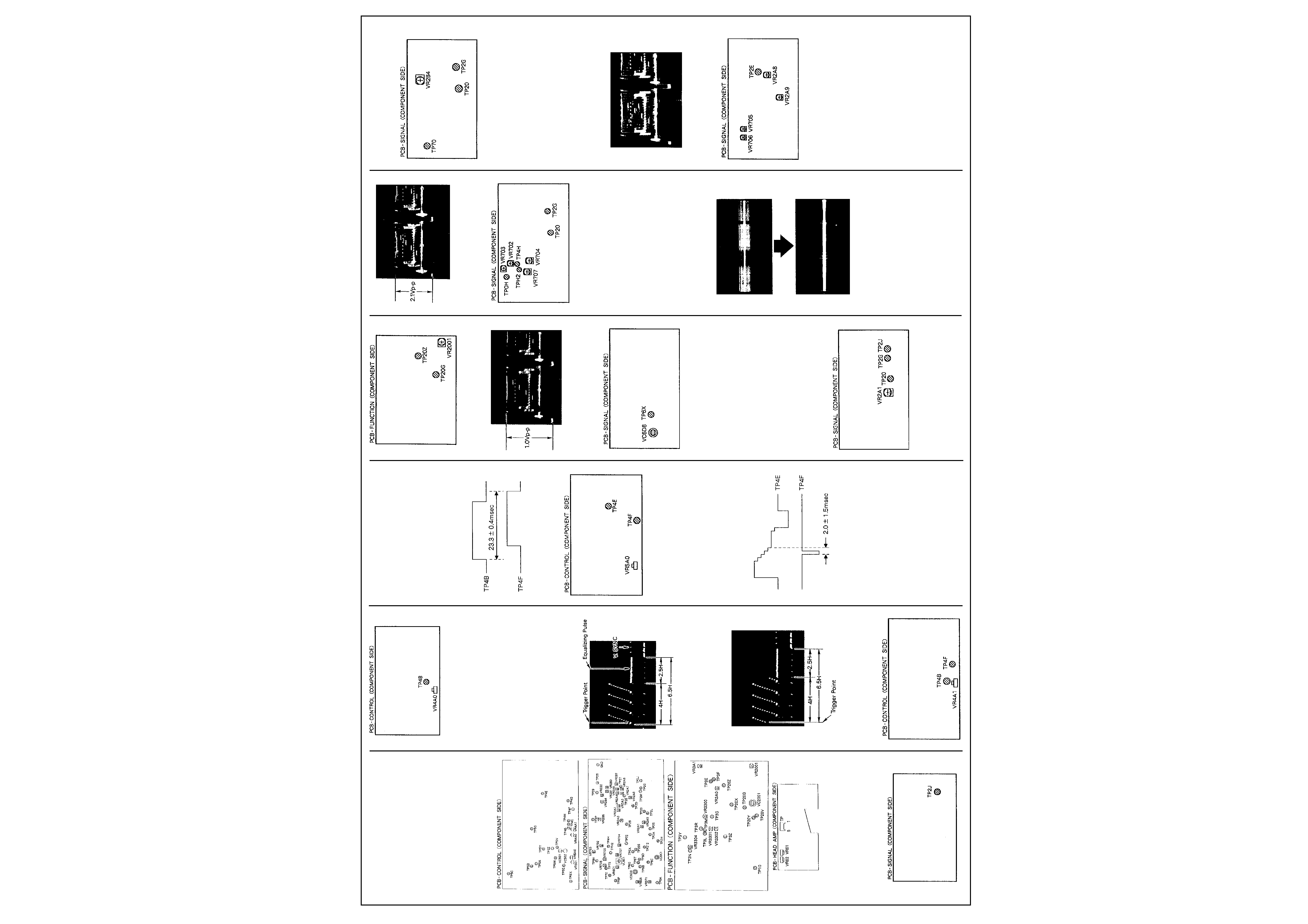
3. Adjust VR4A0 so that the trigger point is
located at 6.5
±1.0H before the vertical
synchronizing signal.
(--)slope
EXT triger(+)
4. Check that the trigger point is located at
6.5
±1.0H before the vertical synchronizing
signal.
(+)slope
2. TRACKING PRESET
MODE
Playback
Alignment tape (Colour bar)
ADJ. METHOD
Oscilloscopes CH-1 to TP4F (CONTROL)
Oscilloscope's CH-2 to TP4B (CONTROL)
VR4A1 (CONTROL)
DIV 0.5V
TIM 5msec
(10:1)
ADJUSTMENT PROCEDURE
1. Set the NORMAL TRACKING control (VR702)
to centre click stop position.
2. Adjust VR4A1 so that the time is
23.3
±0.4msec like the illustration.
3. SLOW AND STILL CIRCUIT
MODE
Playback 3H self recorded tape at 24H mode
Still mode
ADJ. METHOD
Oscilloscope's CH-1 to TP4F (CONTROL)
Oscilloscope's CH-2 to TP4E (CONTROL)
VR5A0 (CONTROL)
DIV 0.2V
TIM 10msec
(10:1)
ADJUSTMENT PROCEDURE
1. Adjust VR5A0 so that the time is 2.0
±1.5msec like the illustration.
2. Adjust VR701 to eliminate any jitter in the still
picture.
Y/C SIGNAL CIRCUIT
4. CG--AGC
MODE
Supply video signal (G card) STOP mode
ADJ. METHOD
Oscilloscope to TP20Z (FUNCTION)
Oscilloscope's GND to TP20G (FUNCTION)
VR2001 (FUNCTION)
DIV 20mV
TIM 10
µsec
(10:1)
ADJUSTMENT PROCEDURE
1. Adjust VR2001 so that the video signal is
1.0Vp-p.
5. CHROMA X'TAL OSC
MODE
Playback Alignment tape (colour bar)
ADJ. METHOD
Frequency counter to TP6X (SIGNAL) VC6D8
(SIGNAL)
ADJUSTMENT PROCEDURE
1. Adjust VC6D8 so that the frequency at TP6X
is 4.433619MHz
±30Hz.
6. S-VHS AGC LEVEL
MODE
Supply video signal (G card) STOP mode
ADJ. METHOD
Oscilloscope to TP2J (SIGNAL) VR2A1 (SIG-
NAL)
DIV 50mV
TIM 10
µsec
(10:1)
ADJUSTMENT PROCEDURE
1 Short circuit TP20 and TP2G
2. Open the VIDEO OUT socket
3. Adjust VR2A1 so that the video signal is
2.1Vp-p.
7. VERTICAL CORRELATION
MODE
Supply video signal (Colour bar) STOP mode
ADJ. METHOD
Oscilloscope's CH-1 to TP0H (SIGNAL)
Oscilloscope's CH-2 to TPH2 (SIGNAL)
Oscilloscope's CH-2 to Invert mode
Oscilloscope to ADD mode
VR702 (SIGNAL)
VR703 (SIGNAL)
TP20(SIGNAL)
TP2G (SIGNAL)
DIV 10mV
TIM 5msec
(10:1)
ADJUSTMENT PROCEDURE
1.Short circuit TP20 and TP2G.
2.Alternate adjustments in the following
sequence: VR703 and VR702 so that the
chroma level is minimum.
ADJ. METHOD
Oscilloscope's CH-1 to TP0H (SIGNAL)
Oscilloscope's CH-2 to TP4H (SlGNAL)
Oscilloscope's CH-2 to Invert mode
Oscilloscope to ADD mode
VR704 (SIGNAL)
VR707 (SIGNAL)
ADJUSTMENT PROCEDURE
3. Alternate adjustments in the following
sequence: VR707 and VR704 so that the
chroma level is minimum.
Note: The volt range of CH-1 and CH-2 must
be the same range.
8. OUTPUT LEVEL OF DCF
MODE
Supply video signal (G card)
ADJ. METHOD
Oscilloscope to
TP7O (SIGNAL)
VR2B4 (SIGNAL)
TP20(SlGNAL)
TP2G (SIGNAL)
DIV 10mV
TIM 10
µsec
(10:1)
ADJUSTMENT PROCEDURE
1. Short circuit TP20 and TP2G.
2. Take the amplitude of waveforme at TP70.
3. Open circuit TP20 and TP2G.
4. Adjust VR2B4 so that the amplitude of
waveform at TP70 is same level of step 2.
9. Y/C SEPARATION
MODE
Supply video signal (Colour bar) STOP mode
ADJ. METHOD
Oscilloscope to
TP2E (SIGNAL)
VR705 (SIGNAL)
VRT06 (SIGNAL)
VR2A8 (SIGNAL)
VR2A9 (SIGNAL)
DIV 20mV
TIM 10
µsec
(10:1)
ADJUSTMENT PROCEDURE
1. Turn VR2A8 and VR2A9 fully counter-
clockwise as seen from component side.
2. Alternate adjustments in the following
sequence: VR705 and VR706 so that the
magenta level is minimum.
Continues next page.
2
MITSUBISHI HS-S5600E
10. SUB-EMPHASIS INPUT LEVEL/S-VHS
CLAMP INPUT LEVEL
MODE
Supply video signal (G card) STOP mode
ADJ. METHOD
Oscilloscope to
TP29 (SIGNAL)
VR2B2 (SIGNAL)
DIV 10mV
TIM 10
µsec
(10:1)
ADJUSTMENT PROCEDURE
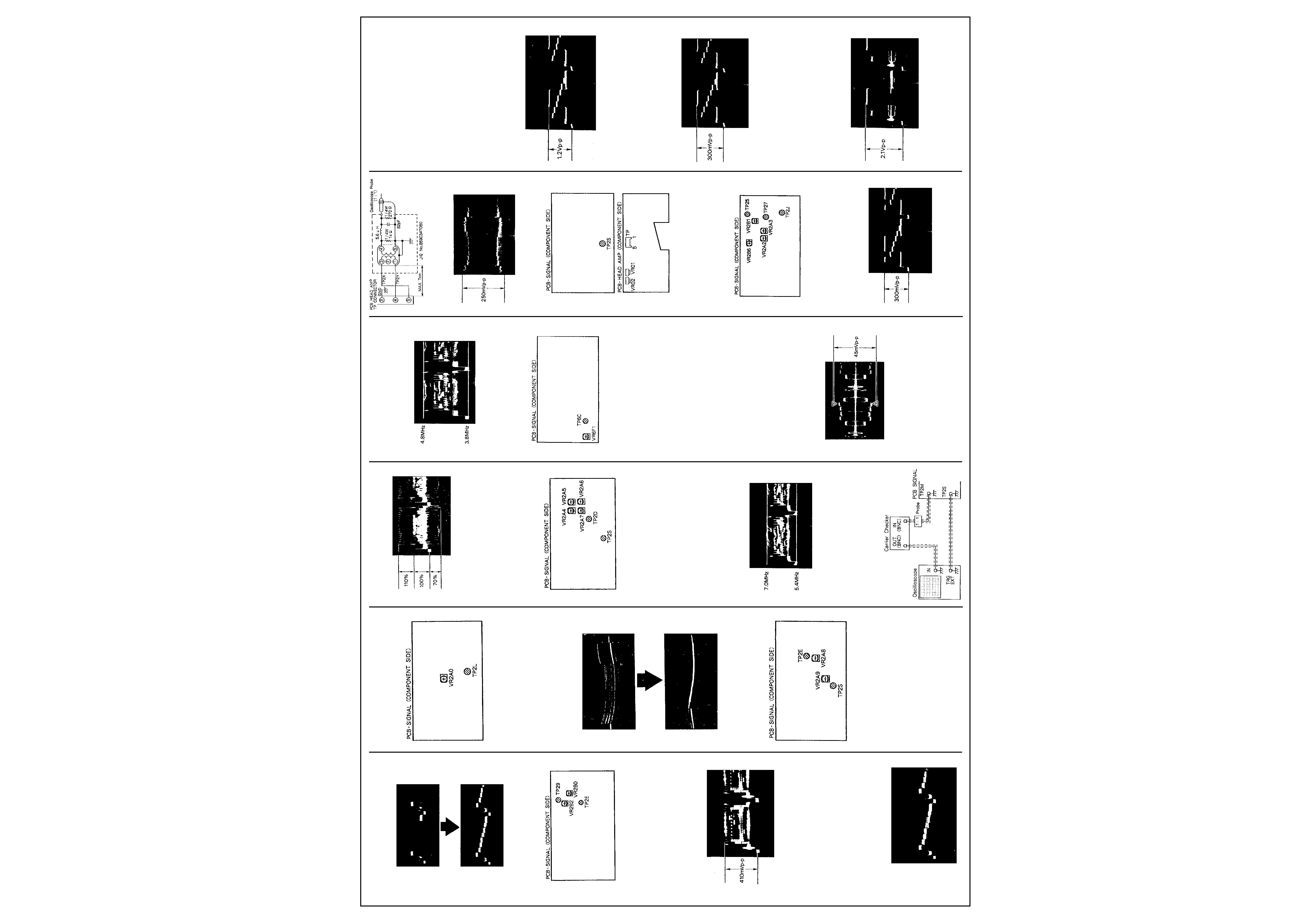
1. Adjust VR2B2 so that the luminance signal is
410mVp-p.
MODE
Supply video signal (Colour bar) STOP mode
ADJ. METHOD
Oscilloscope to
TP2E(SIGNAL)
VR2B0(SIGNAL)
DIV 20mV
TIM 10
µsec
(10:1)
ADJUSTMENT PROCEDURE
2. Adjust VR2B0 so that the video signal level of
S-VHS mode coincides with the video signal
level of Normal VHS mode.
11. Y SIGNAL NOISE REDUCTION
MODE
Supply video signaI (Colour bar) STOP mode
S-VHS SW to OFF
ADJ. METHOD
Oscilloscope to
TP2L (SIGNAL)
VR2A0 (SIGNAL)
DIV 20mV
TIM 2msec
(10:1)
ADJUSTMENT PROCEDURE
1. Adjust VR2A0 so that the signal level is
minimum.
12. WHITE CLIP AND DARK CLIP
MODE
Supply video signal (G card)
3H REC mode
S-VHS SW to ON
MODE
Oscilloscope to
TP2E (SIGNAL)
Oscilloscope's EXT trigger to
TP2S (SIGNAL)
VR2AS (SIGNAL)
VR2A9 (SIGNAL)
DIV 10mV
(VARIABLE mode)
TIM 10
µsec
(10:1)
ADJUSTMENT PROCEDURE
1. Adjust VR2A8 (W-CLIP) and VR2A9 (D-CLIP)
so that the overshoot appearing at the white
side and the undershoot below the sync tip
are 110% and 70% respectively.
MODE
S-VHS SW to OFF
ADJUSTMENT PROCEDURE
2. Check that the white overshoot and the sync
tip undershoot is 100%
±10% and 50%±10%
respectively.
13. CARRIER SET DEVIATION
MODE
Supply video signal (G card) 3M REC mode S-
VHS SW to ON
ADJ. METHOD
Oscilloscope to TP2D (SIGNAL) via the carrier
checker.
Oscilloscope's EXT trigger to TP2S(SIGNAL)
VR2A5 (SIGNAL)
VR2A6 (SIGNAL)
DIV 20mV
TIM 10
µsec
(10:1)
ADJUSTMENT PROCEDURE
1. Adjust VR2A5(FM CAR SET) and VR2A6 (FM
DEV SET) so that the response waveform
5.4MHz (sync-tip) line and 7.0MHz (deviation)
just touch each of the white lines on the
oscilloscope.
MODE
S-VHS SW to OFF
ADJ. METHOD
VR2A4 (SIGNAL)
VR2A7 (SIGNAL)
DIV 50mV
TlM 10
µsec
(1 :1)
ADJUSTMENT PROCEDURE
2. Adjust VR2A4 (FM CAR SET) and VR2A7(FM
DEV SET) so that the response waveform
3.8MMz (sync-tip) line and 4.8MHz (deviation)
just touch each of the white lines on the
oscilloscope.
14. CHROMA AFC
MODE
EXT mode
REC mode
Don't supply a VIDEO signal
ADJ. METHOD
Frequency counter to TP6C (SIGNAL)
VR6F1 (SIGNAL)
ADJUSTMENT PROCEDURE
1. Adjust VR6F1 so that the frequency is
5056.6
±5. 0kHz.
Note: When the VIDEO OUT socket is open
circuit a warning buzzer sounds. Push the
clear button of the front to stop the buzzer.
15. A) COLOUR REC LEVEL
MODE
Supply video signaI (Colour bar)
3H REC mode S-VHS SW to ON
ADJ. METHOD
Oscilloscope to TP connector pin (4) and pin (5)
(HEAD-AMP) via the pad
Oscilloscope's EXT trigger to TP2S (SIGNAL)
VR01 (HEAD-AMP)
DIV 10mV
TIM 10
µsec
(1:1)
ADJUSTMENT PROCEDURE
1. Turn VR02 counterclockwise.
2. Adjust VR01 so that the magenta level is
45mVp-p.
15. B) FM REC LEVEL
ADJ. METHOD
VR02 (HEAD-AMP)
DIV 5mV
TIM 10
µsec
(10:1)
MODE
S-VHS SW to OFF
ADJUSTMENT PROCEDURE
3. Adjust VR02 so that the luminance FM level is
250mVp-p.
ADJUSTMENT PROCEDURE
4. Check that the luminance FM level is 250
±10mVp-p.
16. DEMODULATION SENSITIVITY
MODE
Playback Alignment tape (Colour bar)
ADJ. METHOD
Oscilloscope to
TP27 (SIGNAL)
VR2A2 (SIGNAL)
DIV 10mV
TIM 10
µsec
(10:1)
ADJUSTMENT PROCEDURE
1. Set the VIDEO SW to "COLOUR".
2. Turn VR2A2 fully counterclockwise as seen
from component side.
3. Turn VR2A2 clockwise so that the demodula-
tion signal is 300mVp-p.
MODE
Playback S-VHS
Alignment tape (PC(S))
ADJ. METHOD
Oscilloscope to
TP25 (SIGNAL)
VR2A3 (SIGNAL)
DIV 50mV
TIM 10
µsec
(10:1)
ADJUSTMENT PROCEDURE
4.Turn VR2A3 fully counterclockwise as seen
from component side.
5.Turn VR2A3 clockwise so that the demodula-
tion signal is 1.2Vp-p.
ADJ. METHOD
Oscilloscope to
TP27 (SIGNAL)
VR2B1 (SIGNAL)
DIV 10mV
TIM 10
µsec
(10:1)
ADJUSTMENT PROCEDURE
6. Adjust VR2B2 so that the level is 300mVp-p.
ADJ. METHOD
Oscilloscope to
TP2J (SIGNAL)
VR2B6 (SIGNAL)
DIV 50mV
TIM 10usec
(10:1)
ADJUSTMENT PROCEDURE
7. Open the VIDEO OUT terminal.
8. Adjust VR2B6 so that the video signal is
2.1Vp-p.
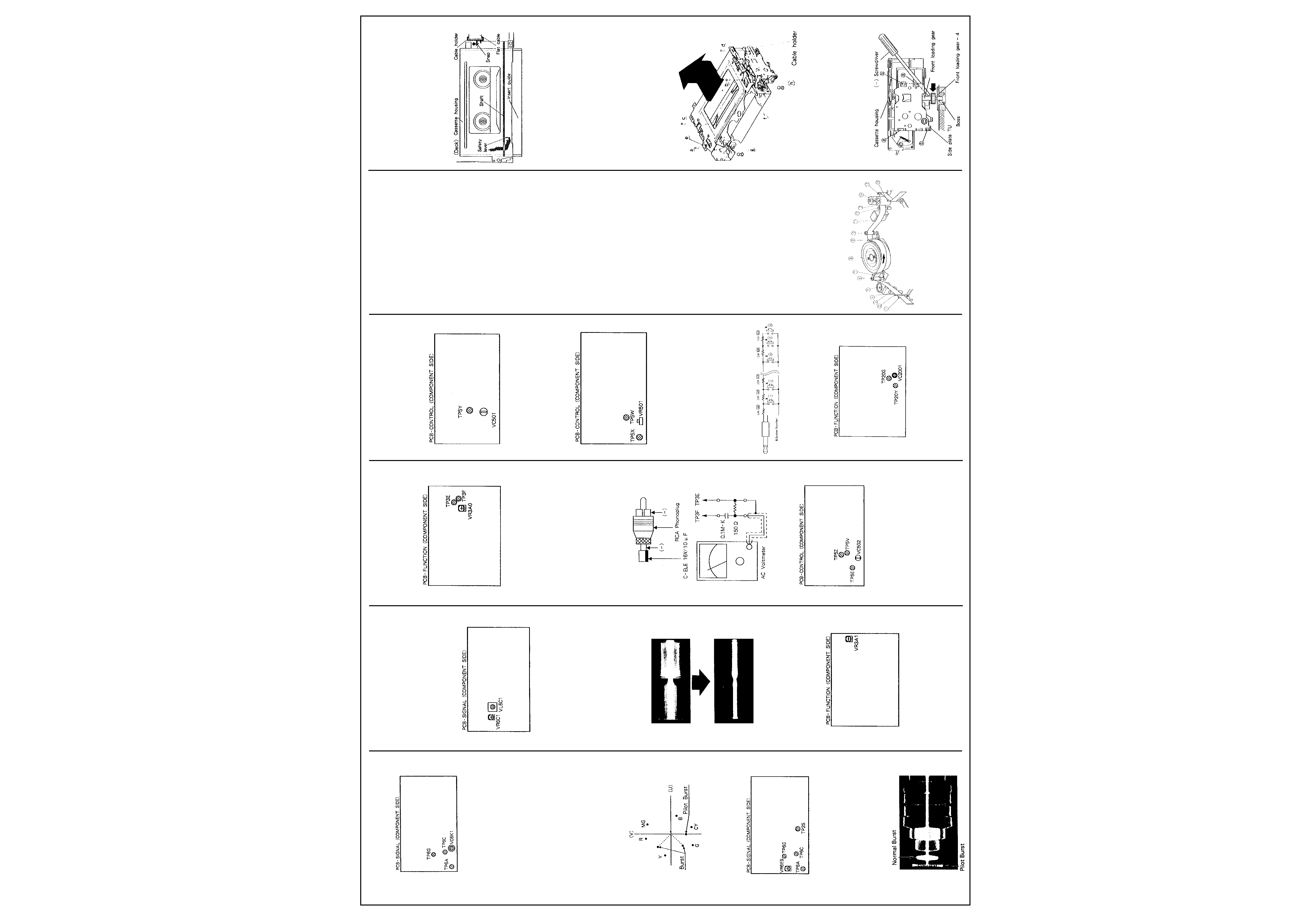
17. PILOT BURST PHASE
MODE
Supply video signal (Colour bar) STOP mode S-
VHS SW to ON
Electrical Adjustments
Cont'd
3
MITSUBISHI HS-S5600E
ADJ. METHOD
Vector scope to
TP6A (SIGNAL)
VC6K1 (SIGNAL)
TP6X (SIGNAL)
TP6C (SIGNAL)
TP6G (SIGNAL)
ADJUSTMENT PROCEDURE
1. Short circuit TP6C and TP6G.
2. Connect the EXT ø REF terminal of vector
scope to TP6X.
3. Locate the burst to the fixed position, and
adjust VC6K1 so that the pilot burst located
270
° from U-axis.
4. Adjust VR6E9 so that the pilot burst level is
about 1.1 times the burst level.
ADJ. METHOD
VR6E9 (SIGNAL)
ADJUSTMENT PROCEDURE
5. Alternate adjustments of step 3 and step 4.
18. PILOT BURST LEVEL
MODE
Supply video signal (Colour bar)
STOP mode S-VHS SW to ON
ADJ. METHOD
Oscilloscope to TP6A (SIGNAL)
Oscilloscope's EXT trigger to
TP2S (SIGNAL)
VR6E9 (SIGNAL)
TPSC (SIGNAL)
TP6G (SIGNAL)
DIV 20mV
TIM 5
µsec
(10:1)
ADJUSTMENT PROCEDURE
1. Short circuit TP6C and TPSG.
2. Adjust VR6E9 so that the pilot burst amplitude
is 1.1 times the burst signal in S-VHS mode
(5803:ON).
3. Check that the pilot burst signal disappears in
Normal VHS mode (S803:OFF)
19. CHROMA NOISE REDUCTION
MODE
Playback
Alignment tape (Colour bar)
ADJ. METHOD
Oscilloscope to
TP6P (SIGNAL)
VL6C1 (SIGNAL)
VRBC1 (SIGNAL)
DIV 5mV
TIM 2msec
(10:1)
ADJUSTMENT PROCEDURE
1. Alternate adjustments in the following
sequence: VL6C1 and VR6C1 so that the
chroma level is minimum.
2. Check that the chroma level is less than
30mVp-p.
AUDIO CIRCUIT
* Supply video signal to the VIDEO IN socket.
20. PLAYBACK AUDIO LEVEL
MODE
Playback Alignment tape (Colour bar, 1kHz
audio)
ADJ. METHOD
AC voltmeter to AUDIO IN socket VR3A1
(FUNCTION)
ADJUSTMENT PROCEDURE
1. Adjust VR3A1 for an Audio output level of -
6dBs (388m Vr.m.s).
2. Confirm that the level fluctuation is less than
±1dBs. If level fluctuation is over ±1dB then
check the mechanical adjustments.
21. AUDIO BIAS LEVEL
MODE
3H REC mode
ADJ. METHOD
AC Voltmeter to TP3E (FUNCTION) and TP3F
(FUNCTION) through a high pass filter.
Note: Be careful that the AC Voltmeter housing
does not touch the VCR chassis.
VR3A0 (FUNCTION)
ADJUSTMENT PROCEDURE
1. Insert a shorted RCA type Phonoplug into the
AUDIO IN socket.
2. Confirm that the monitor TV etc. does not
affect the indication of the AC voltmeter and
then adjust VR3A0 for a level of 2.8mVr.m.s.
Note: Do not set the VCR to PLAY mode with
the AC voltmeter connected. (The audio
amplifier will be over-loaded.)
TIMER CIRCUIT
22. CLOCK CRYSTAL
MODE
----------
ADJ. METHOD
Frequency counter to TP5V (CONTROL) via
CM-1 output of oscilloscope
Note: Attach insulating tube to tip of CH-1 probe
and connect it to TP5V
TP5E (CONTROL)
TP5Z (CONTROL)
VC502 (CONTROL)
ADJUSTMENT PROCEDURE
1. Unplug the power cord from the AC source.
2. Supply DC voltage 3.90
±0.05V to TP5Z(--)
and TP5E(+).
3. Adjust VC502 so that the frequency is 32.
768kMz
±0. 1Hz.
23. 6.29MHZ CRYSTAL
ADJ. METHOD
Frequency counter to TP5Y (CONTROL) VC501
(CONTROL)
ADJUSTMENT PROCEDURE
1. Adjust VC501 so that the frequency is
1.572864MHz
±2Mz.
24. REMOTE CONTROL CIRCUIT
ADJ. METHOD
Frequency counter's input A to TP5W (CON-
TROL) and input B to TP5X (CONTROL) VR501
(CONTROL) Trigger of input A and B to (--)
ADJUSTMENT PROCEDURE
1. Make remote control JIG. as shown in Fig. 24-1.
Note: When pushing the 32 button, confirm
that entire resistor value is 1056
±0. 2k.
2. Insert the remote control JIG to the REMOTE
jack.
3. Push the 32 button of remote control JlG and
adjust VR501 so that the period is 31. 74
±
0.05msec.
Fig. 24-1
25. SIZE OF DISPLAY CHARACTER
MODE
Supply video signal (Colour bar) STOP mode
ADJ. METHOD
Frequency counter to TP20Y (FUNCTION)
Frequency counter's GND to TP20G (FUNC-
TION) VC2001 (FUNCTION)
ADJUSTMENT PROCEDURE
1. Turn on the DISPLAY button (S807) so that
the USER SELECTION display appears, and
change the contents of TIME DATE SIZE to
small.
2. Change the DISPLAY to DAY and PRESENT
TIME display, and adjust VC2001 so that the
frequency is 9.90
±0.1MHz.
Mechanical Adjustments
1. Cleaning of Deck
The following parts require cleaning whenever
serviced to maintain satisfactory erforma nce.
1 -1 Video Head
A.Clean the video heads in the following method
if dust and other foreign objects on the video
heads disturb the normal playback of images:
Dampen video head cleaning cloth with
alcohol. Hold the cloth against the drum and
turn the drum slowly counterclockwise to
clean. Note: Do not directly touch the head
attached to the upper drum. The head is very
hard but brittle to impact, especially in the
vertical direction. Do not apply force in the
vertical direction.
B. Allow residual alcohol to dry thoroughly
before running tape otherwise, the liquid may
stick to and damage the tape.
1-2 Tape Transport (Refer to Fig. 1 -1.)
Clean the following parts of the tape transport.
1.
Tension regulation arm S
2.
Tension arm
3.
Supply guide pole
4.
FE head
5.
Impedance roller
6.
Supply guide roller
7.
Supply slant pole
8.
Upper and lower drum
9.
Takeup slant pole
10. Takeup guide roller
11.
A/C head
12. Takeup guide pole
13. Pinch roller
14. Capstan shaft
15. Takeup guide arm
16. Tension regulation arm T
A.Clean the tape transport with gauze damp-
ened with alcohol, except the supply and
takeup guide rollers. If Guide rollers are
stained with dust, clean them with dry gauze
or exchange them for new parts.
B.Allow residual alcohol to dry thoroughly before
running a tape. Otherwise the liquid may stick
to and damage the tape.
1 -3 Reel Disk Drive System
A.Clean the reel disk braking surfaces and the
ribbed belt.
B.Clean the above parts with gauze dampened
with alcohol.
C.Allow the residual liquid to dry thoroughly
before operating the reel disk.
Fig.1-1
2. Replacement of Major Parts
2-1 Cassette Housing
2-1-1 Removal (Refer to Fig. 2-1-1~2-1-2.)
A. Set the VCR to the eject mode.
B. Remove the top panel, bottom panel, and
front panel.
C.Unfasten the snap on the cable holder and
remove the cable holder from the cassette
housing as shown in Fig. 2-1-1.
D.Unscrew four cassette housing fastening
screws (a), (b), (c) and (d). Raise the cassette
housing slowly in the direction shown by the
arrow.
Fig. 2-1-1
2-1-2 Installation (Refer to Fig. 2-1-1~2-1-3.)
A.Slowly lower the cassette housing onto the
main plate of the deck so that the safety lever
enters between the insert guide and the shaft
as shown in Fig. 2-1-1. Align the two position-
ing holes (e) and (f) and the two U holes (g)
and (h) located on the cassette housing with
the matching holes in the deck.
B.In step A above, if the front loading gear of the
cassette housing does NOT engage the boss
on the main plate, carefully push the gear
toward the front of the VCR using a small-
diameter screwdriver, as illustrated in Fig. 2-
1-3. If the gear still will not engage, rotate the
Front Loading Gear a few degrees from the
below the deck until the gear engages the
boss correctly.
C.Fasten the housing to the deck with the four
screws (a), (b), (c) and (d).
Fig. 2-1-2
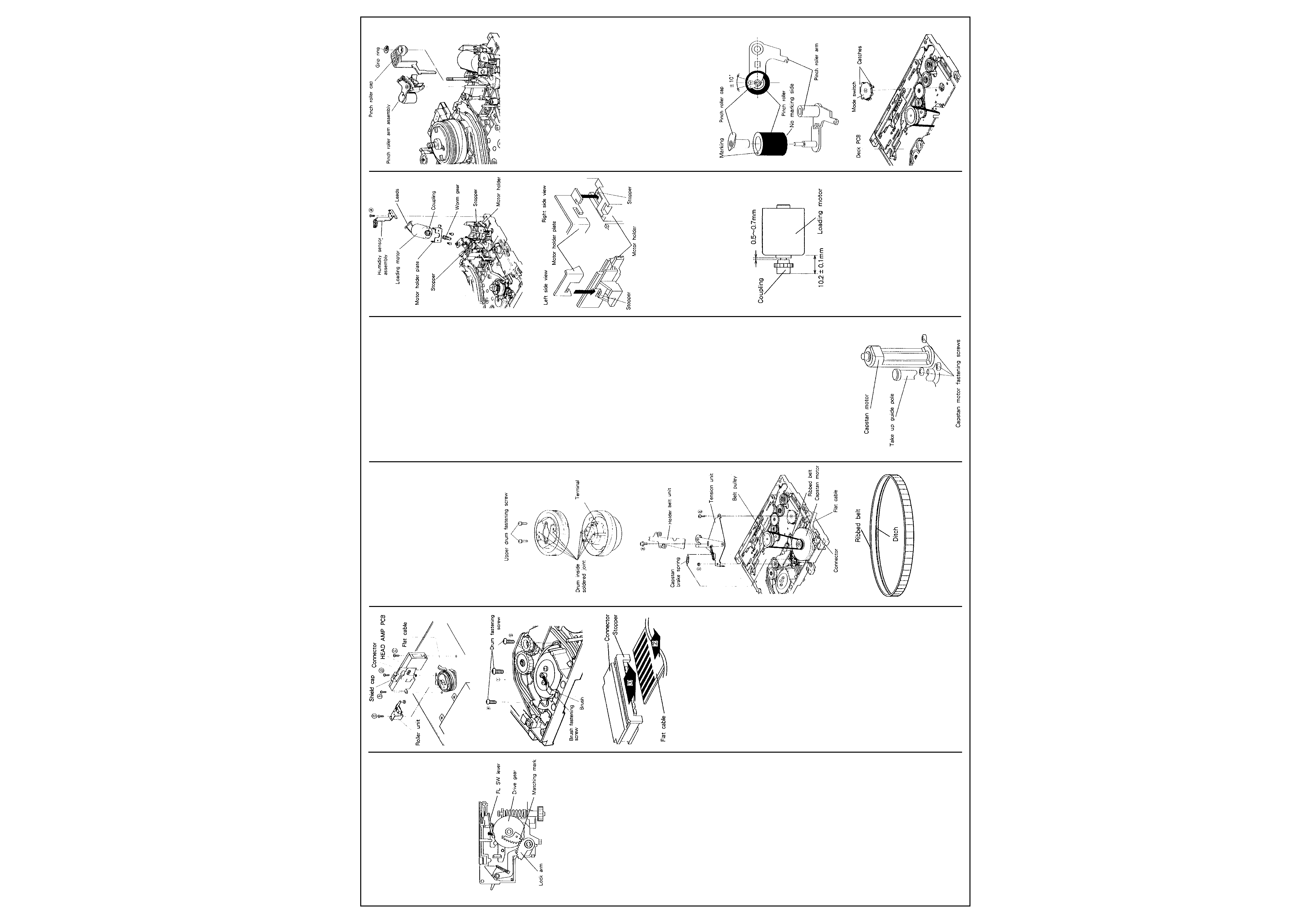
2-2 Lock arm and Drive gear
2-2-1 Removal (Refer to Fig. 2-1-3~2-2.)
A. Unfasten four snaps (a), (b), (c) and (d) as
shown in Fig. 2-1-3, and remove the side
plate TU.
B.Turn the FL SW lever clockwise to separate
the FL SW lever from the drive gear, and pull
the lock arm and drive gear to remove them
from the shaft as shown in Fig. 2-2.
Fig. 2-1-3
Electrical Adjustments
Cont'd
4
MITSUBISHI HS-S5600E
2-2-2 Installation (Refer to Fig. 2-1-3~2-2.)
A.Install the drive gear on the shaft as shown in
Fig. 2-2.
B.Line the matching mark on the drive gear and
beginning of gear section on the lock arm as
shown in Fig.2-2, and install the lock arm.
C.Install the side plate TU to the cassette
housing, and secure it with four snaps (a), (b)
(c) and (d) as shown in Fig. 2-1-3 (see
previous page).
Fig. 2-2
2-3 Drum Assembly
2-3-1 Removal (Refer to Fig. 2-3-1~2-3-3)
A.Disconnect the roller units connector (CP)
from the control PCB.
B. Unscrew the roller unit fastening screw (a)
and remove the roller unit.
C. Unscrew three fastening screws (b), (c) and
(d) and remove the head amplifier PCB which
is connected to the drum assembly.
D.Unscrew the brush fastening screw and
remove the brush as shown in Fig. 2-3-2.
Note: The cable and connector between the
drum and head amplifier may be damaged if
the cable is pulled strongly, as the cable is
short. Remove the shield cap of the PCB,
raise the PCB slightly and disconnect the flat
cable. Removal method for the flat cable
connector and stopper is shown in Fig. 2-3-3.)
Disconnect the grounding wire and remove
the head amplifier PCB.
E.Unscrew three drum fastening screws (e), (f)
and (g) from the reverse side of the deck.
F. Remove the drum assembly by raising it with
care not to touch other parts around the drum
assembly.
G.Disconnect the connectors from the drum
assembly.
2-3-2 Installation (Refer to Fig. 2-3-1, 2-3-2.)
A.Connect the connectors to a new drum
assembly.
B.Place the new drum assembly on the main
plate of the deck slowly being careful not to
touch other parts.
C.Fasten the drum assembly with three
fastening screws (e), (f) and (g) on the
reverse side of the deck.
D.Fasten the brush with the fastening screw.
E.Connect the head amplifier PCB to the drum
assembly and fasten the PCB with three
screws (b), (c) and (d).
F. Connect the roller unit s connector (CP) to the
control PCB.
G. Fasten the roller unit with the fastening screw
(a). Note: Conduct the mechanism inter-
changeability adjustment outlined in Para . 3
to give optimum performance when the drum
assembly is replaced.
Fig. 2-3-1
Fig. 2-3-2
Fig. 2-3-3
2-4 Upper Drum
2-4-1 Removal (Refer to Fig. 2-4-1.)
A.Unscrew the roller unit fastening screw and
remove the roller unit.
B.Unsolder two inside soldered terminals of
each head on the upper drum.
C.Unscrew the upper drum fastening screws.
D.Remove the upper drum slowly and carefully.
Note: If the upper drum is difficult to remove,
heat the upper drum fastening screw holes
with a soldering iron, and the drum will be
easily removed.
2-4-2 lnstallation (Refer to Fig. 2-4-1.)
Note: Handle the upper drum carefully as the
video heads are fragile.
A.Position the lower drum so that the hole in the
shaft faces the operator. Align the upper drum
with the lower drum so that the CH1 mark on
the upper drum is on the right side, and
couple the drums.
B.Fasten the upper drum with two screws.
(Tighten the screws alternately.)
C.Solder the terminals not soldered on the
upper drum.
D. Clean the video heads as outlined in Para.1-
1.
2-5 Ribbed Belt
2-5-1 Removal (Refer to Fig. 2-5)
A.Remove the screw (a) retaining the holder belt
unit, and remove the holder belt unit.
B.Detach the capstan brake spring from the
tension unit and capstan brake unit.
C.Remove the screw (b) retaining the tension
unit and the nut (c), and remove the tension
unit.
D.Remove the ribbed belt from the capstan
motor and the belt pully.
2-5-2 Installation (Refer to Fig. 2-5-1, 2-5-2)
A.Confirm that the groove of the new ribbed belt
is turned to the inside, as shown in Fig. 2-5-2,
and then install the ribbed belt to the capstan
motor and the belt pulley.
B. lnstall the tension unit to the main plate with
the screw (b) and the nut (c).
C.Fasten the capstan brake spring to the
tension unit and capstan brake unit.
D.Install the holder belt unit to the main plat with
the screw (a).
Note: Make certain that the new belt is free
from grease, before installing.
Fig. 2-4-1
Fig. 2-5-1
Fig. 2-5-2
2-6 Capstan Motor
2-6-1 Removal (Refer to Fig. 2-5, 2-6)
A.Disconnect the flat cable.
B.Detach the capstan brake spring from the
tension unit and capstan brake unit.
C.Remove the screw (a) retaining the tension
unit and the nut (b), and remove the tension
unit.
D.Remove the ribbed belt.
E.Remove three fastening screws shown in Fig.
2-6 and remove the capstan motor.
CAUTION:
Restrain the capstan motor as the three screws
are removed, since an un-restrained motor may
damage other parts of the deck. When perform-
ing removal or installation of the capstan
motortake care that the outside of the rotor's rim
is not greased.(Refer to Fig. 2- 5.)
If greasy components are attached on the
outside of the rotor's rim, wipe them off with a
dry cloth because they may cause defects
during special effects playback.
2-6-2 Installation (Refer to Fig. 2-5, 2-6.)
A.Fasten the motor with three fastening
screws.(Refer to Fig. 2-6.)
B.Install the ribbed belt.
C.Install the tension unit to the main plate with
the screw (a) and nut (b).
D.Fasten the capstan brake spring to the
tension unit and capstan brake unit.
E.Connect the flat cable.
2-7 Loading Motor
2-7-1 Removal (Refer to Fig. 2-7-1, 2-7-2.)
A.Set the VCR to the eject mode.
B.Unscrew the humidity sensor assembly
fastening screw (a) and remove the humidity
sensor assembly. (Refer to Fig. 2-7-1.)
C.Disconnect the wires from the loading motor.
D.Remove two stoppers securing the motor and
the motor holder plate. (Refer to Fig. 2-7-2.)
E.Slide the motor and motor holder plate away,
and then raise them to remove.
F. Unscrew two screws and detach the motor
holder plate from the motor.
G.Disconnect the coupling from the motor.
2-7-2 Installation (Refer to Fig. 2-7-1~2-7-3.)
A.Fasten the coupling to a new loading motor.
(Refer to Fig. 2-7-3.)
B.Fasten the motor holder plate to the motor
with two screws.
C.Place the motor and motor holder plate in the
motor holder at the rear of the deck.
D.Turn the motor shaft so that the coupling on
the loading motors matches the worm gear of
the motor holder. Slide the loading motor
forward and secure it with the stoppers.
E. Solder the leads to the loading motor. (Brown
lead wire to the positive terminal and red lead
wire to the negative terminal.)
F. Fasten the humidity sensor assembly with the
fastening screw (a).(Refer to Fig. 2-7-1.)
Fig. 2-6
Fig. 2-7-1
Fig. 2-7-2
2-8 Pinch Roller
2-8-1 Removal (Refer to Fig. 2-8-1, 2-8-2.)
A.Set the VCR to the eject mode.
B.Remove the pinch roller arm cap and the grip
ring which secures the pinch roller arm
assembly.
C.Pull the pinch roller arm assembly upwards to
remove.
D.Remove the pinch roller cap from the pinch
roller arm, and remove the pinch roller. (Refer
to Fig. 2-8-2.)
Fig. 2-7-3
2-8-2 Installation (Refer to Fig. 2-8-1, 2-8-2.)
A.Assemble the pinch roller cap and the pinch
roller to the pinch roller arm by exercising
care with the installation angle of the pinch
roller cap and the marking of the Pinch Roller.
(Refer to Fig. 2-8-2.)
B.Assemble the pinch roller assembly to the
shaft on the main plate.
C.Secure the pinch roller arm assembly with the
pinch roller arm cap and the grip ring.
Fig. 2-8-1
Fig. 2-8-1
2-9 Mode Switch
Note: Replace the mode switch with the VCR in
the eject mode.
2-9-1 Removal (Refer to Fig. 2-9-1)
A.Unsolder the five soldered joints of the mode
switch from the deck PCB.
B.Unfasten two catches fastening the switch to
the deck PCB assembly. (Exercise care as
the catches may be broken off.)
C.Remove the mode switch slowly while
assuring that the soldered joints are all
unsoldered.
2-9-2 lnstallation (Refer to Fig. 2-9-1,2-9-2.)
A.Line the matching marks of the mode switch.
(Refer to Fig. 2-9-2.)
B.Finally adjust the mode switch so that
continuity at each terminal shall be as given in
the illustration.
C.Fasten the switch to the deck PCB with care
so that the switch shall not turn, and secure
with two catches.(Refer to Fig. 2-9-1.)
D.Solder the five terminals which connect the
mode switch to the deck PCB assembly.
Fig. 2-8-2
Fig. 2-9-1
Mechanical Adjustments
Cont'd
5
MITSUBISHI HS-S5600E
Fig. 2-9-2
2-10 Supply Reel Disk
2-10-1 Removal (Refer to Fig. 2-10-1~2-10-3.)
A.Remove the cassette housing as in Para. 2-1-1.
B.Unscrew the screw (a) which fastens the T
band holder.
C.Unfasten the catch of the T band holder from
the main plate with a small screw driver etc.
as shown in Fig. 2-10-2. Raise and remove
the T band holder with care not to score or
dirty the tension brake belt.
D.Detach the tension spring from the tension
arm and the tension lever.
E.Remove the grip ring (b) which secures the
tension arm. Raise the tension arm upward to
remove it from the shaft.
F. Detach the tension regulation spring S from
the tension regulating arm S and the tension
lever.
G.Detach the safety lever spring from the safety
lever and the tension lever.
Fig. 2-10-1
H.Raise the tension lever avoiding the main
brake S and remove the lever from the shaft.
(Refer to Fig. 2-10-3.)
I. Raise the tension regulation arm S and
remove it from the shaft.
J.While turning the main brake S slightly
clockwise to separate the brake from the
supply reel disk, and raise the supply reel disk
to remove it from the shaft. (Refer to Fig. 2-10-3).
Fig. 2-10-2
Fig. 2-10-3
2-10-2 Installation
(Refer to Fig. 2-10-4~2-10-7.)
A.Turn the main brake S slightly clockwise to
separate it from the supply reel disk shaft,
and mount the supply reel disk on the shaft so
that the reel gear meshes with the gear of the
supply reel disk.
B.Assemble the tension regulation arm S to the
shaft.
C.Assemble the tension lever to the shaft
avoiding the main brake S.
Note: Install the tension lever so that the pin
at the lower part of the lever shall be in front
of the slot in the main plate (viewing the
front).
D.Fasten the safety lever spring to the safety
lever and the tension lever.
E.Fasten the tension regulation spring S to the
tension regulation arm S and the tension ever.
Fig. 2-10-4
F. Assemble the tension arm to the shaft and
secure the arm with the grip ring (b). (Refer to
Fig. 2-10-5.)
G.Fasten the tension spring to the tension arm
and the tension lever.(Refer to Fig. 2-10-5.)
H.Assemble the T band holder to the main plate
with care not to score or dirty the tension
brake belt, and secure the holder with the
screw (a) lightly.(Refer to Fig. 2-10-5.)
Note: In the assembly of the T band holder,
make certain that the hook of the holder
positively engages with the reverse side of
the main plate. lf the hook is difficult to
engage with the main plate, push the hook
lightly with a small screw driver etc.(Refer to
Fig. 2-10-2.)
I. Separate the main brake S and the tension
regulation arm S from the supply reel disk and
make certain that the disk turns freely.
J.Place the reel disk adjusting jig (Part Number
859C342020) in the reference position on the
main plate. (Refer to Fig. 2-10-6.)
K.Slowly turn the jig about the point A and make
sure that the height of the supply reel disk
flange shall agree with the point B on the
supply disk adjusting side of the jig (marked
SP). (Refer to Fig. 2-10-7.)
L.If the height of the disk is not satisfactory, hold
the disk so that it dose not turn, and turn the
height adjusting screw at the top of the disk to
adjust the height. (Refer to Fig. 2-11-3.)
A) Turn the screw clockwise if the measured
height is low.
B) Turn the screw counterclockwise if the
measured height is high.
M.On completion of adjustment, lock the height
adjusting screw by burning it with the tip of
the hot iron.
N.Install the cassette housing as in Para. 2-1-2.
O.Adjust back tension and tension pole position
as outlined in Para. 3- 1.
Fig. 2-10-5
Fig. 2-10-6
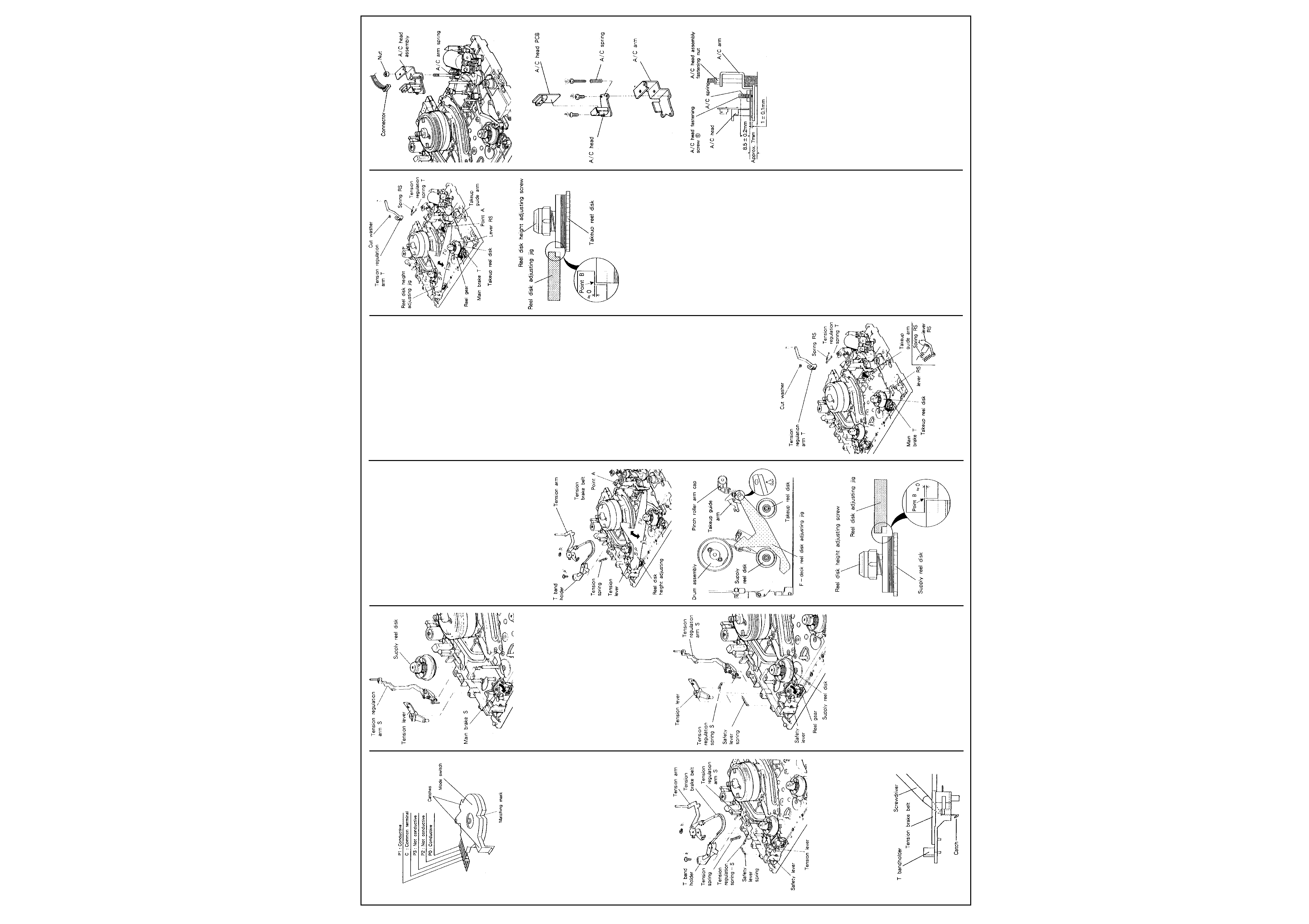
Fig. 2-10-7
2-11 Takeup Reel Disk
2-11-1 Removal (Refer to Fig. 2-11-1.)
A.Remove the cassette housing as in Para. 2-1-1.
B.Detach the spring RS and the tension
regulation spring T from the tension regulation
arm T and the lever RS.
C.Remove the cut washer which fastens the
tension regulation arm T.
D.Turn the takeup guide arm slightly clockwise
and raise the tension regulation arm T to
remove it from the shaft.
E.Turn the main brake slightly counter-clockwise
to separate the brake from the takeup reel
disk and raise the disk upwards to remove it
from the shaft.
2-11-2 Installation
(Refer to Fig. 2-11-2, 2-11-3.)
A.Turn the main brake T slightly counter-
clockwise to release the takeup reel disk
shaft. Slip the takeup reel disk onto the shaft
so that the gear of the takeup reel shall mesh
with the reel gear.
B.Turn the takeup guide arm slightly clockwise
and install the tension regulation arm T to the
shaft. Secure the arm with a cut washer.
C.Fasten the tension regulation spring T and the
spring RS to the tension regulation arm T and
the lever RS.
D.Separate the main brake T and the tension
regulation arm T from the takeup reel disk and
make certain that the takeup reel disk turns
freely.
E. Place the reel disk adjusting jig (Part Number
859C342020) in the reference position on the
main plate. (Refer to Fig. 2-10-6.)
F. Turn the jig slowly about the point A
towards the takeup reel disk to make certain
that the height of the disk flange agrees
with the point B on the takeup side of the
jig (marked TU). (Refer to Fig. 2- 11 -3.)
G. If the height of the disk is not satisfactory,
hold the disk so that it shall not turn, and
turn the height adjusting screw at the top of
the disk to adjust the height. (Refer to Fig. 2-
11-3.)
A) Turn the screw clockwise if the measured
height is low.
B) Turn the screw counterclockwise if the
measured height is high.
H. On completion of height adjustment, lock the
adjusting screw by burning it with the tip of the
hot iron.
I. Install the cassette housing as in Para. 2-1-2.
Fig. 2-11-1
Fig. 2-11-2
Fig. 2-11-3
2-12 A/C Head
2-12-1 Removal (Refer to Fig. 2-12-1, 2-12-2.)
A.Disconnect the connector from the A/C head
PCB.
B.Remove the nut which fastens the A/C head
assembly.
C.Raise upwards and remove the A/C head
assembly from the shaft by paying attention
to the A/C arm spring which turns the A/C
head assembly clockwise.
D.Remove three A/C head fastening screws (a),
(b) and (c) and the A/C spring shown in Fig.
2-12-2, and remove the A/C head from the A/
C arm.
E.Unsolder the A/C head PCB from the A/C
head.(Refer to Fig. 2-12-2.)
2-12-2 Installation
(Refer to Fig. 2-12-1~2-12-3.)
A.Solder the A/C head PCB to the A/C head.
(Refer to Fig. 2-12-2.)
B.Fasten the A/C head to the A/C arm with three
screws (a), (b), and (c) and the A/C spring.
Note: Install the A/C head to the A/C arm so
that the base surface of the A/C head shall be
parallel to the A/C arm, and their spacing and
the A/C head installation screw (c) height
shall be as specified in Fig. 2-12-3.
C.Assemble the A/C head assembly to the shaft
while turning the A/C arm spring counter-
clockwise about 60
° . (Refer to Fig. 2-12-1.)
D.Tighten the A/C head assembly fastening nut
so that the base surface of the A/C head shall
be about 7mm above the main plate
surface.(Refer to Fig. 2-12-3.)
E. Plug in the connector to the A/C head PCB.
(Refer to Fig. 2-12-1.)
F. Conduct the A/C head adjustment and the
phase adjustment as outlined in Para. 3-3
and 3-4.
Fig. 2-12-1
Fig. 2-12-2
Fig. 2-12-3
2-13 Take Up Guide Arm
2-13-1 Removal (Refer to Fig. 2-13-1.)
A.Set the VCR in the eject mode.
B.Remove the pinch roller arm assembly. (Refer
to Para. 2-8 "Pinch Roller.")
C.Raise and separate the pinch roller cam and
the TU-G gear arm from the shaft at the same
time.
D.Remove the takeup guide arm fastening nut.
Raise and separate the takeup guide arm
from the shaft with care not to lose the TU-G
spring.
2-13-2 Installation
(Refer to Fig. 2-13-1~2-13-3.)
A.Install the TU-G spring and the takeup guide
arm so that one end of the TU-G spring is
fastened to the takeup guide arm and the
other end is fastened to the hook of the main
plate. Secure them with the fastening nut
temporarily.
B.Place the reel disk adjusting jig (for the F
deck) in the reference position on the main
plate (Refer to Fig. 2-10-6). Tighten the
Mechanical Adjustments
Cont'd