MITSUBISHI DIGITAL ELECTRONICS AMERICA, INC.
9351 Jeronimo Road, Irvine, CA 92618-1904
Copyright © 2004 Mitsubishi Digital Electronics America, Inc.
All Rights Reserved
CAUTION:
Before servicing this chassis, it is important that the service person read the "SERVICE SAFETY" section in this
manual.
MITSUBISHIELECTRIC Ser
Ser
Ser
Ser
Service
vice
vice
vice
vice
Manual
Manual
Manual
Manual
Manual
2004
2004
2004
2004
2004
· Weight and dimensions shown are approximate.
· Design specifications are subject to change without notice.
PLASMA DISPLAY PANEL
SPECIFICATIONS
· Power
: AC 120V, 50/60Hz
540W (Typical)
6.7A (Maximum)
· Signals
Sync Range
: Horiz : 15.5 to 110kHz
(Automatic : step scan)
: Vert : 50.0 to 120 Hz
(Automatic : step scan)
Input Signals
: RGB, HD*1,
DVD*1, DTV*1
· Input Terminals
RGB
: Visual 1 (Analog) : Mini D-sub 15-pin
Visual 2 (Analog) : BNC (R,G,B,H/CS,V)*2
Visual 3 (M-LINK) : MONITORLINKTM (HDMI)
Video
: Visual 1 : BNC
Visual 2 : RCA-pin
Visual 3 : S-Video: DIN 4-pin
DVD/HD/DTV
: Visual 1 RCA-pin (Y,PB[CB},PR{CR])*1
Visual 2 BNC (Y,PB[CB},PR{CR])*1 *2
Visual 3 (M-LINK) : MONITORLINKTM (HDMI)
Audio
: Stereo RCA x 3 (Selectable)
External Control
: D-sub 9-pin MONITORLINKTM (RS232C)
· Sound Output : 9W+9W at 6 ohms
· Dimensions
: (W)57.9" (H)34.7" (D)4.7"
(W)1470 (H)880 (D)119 mm
· Weight
: 134.5 lbs / 61 kg
PD-6150
*1 HD/DVD/DTV Input Signa ls supporte d:
480P (60Hz)
480I (60Hz)
525P (60Hz)
525I (60Hz)
576P (50Hz)
576I (50Hz)
625P (50Hz)
625I (50Hz)
720P (60Hz)
1035I (60Hz)
1080I (50Hz)
1080I (60Hz)
*2 The 5-BNC conne ctors are used as
RGB/PC2 and HD/DVD2 input.
Select one of them under "BNC SELECT".


SERVICE SAFETY..................................................................................................................... 2-1
TROUBLESHOOTING ............................................................................................................... 3-1
METHOD OF ADJUSTMENTS .................................................................................................. 4-1
METHOD OF DISASSEMBLY ................................................................................................... 5-1
PARTS LIST............................................................................................................................... 6-1
CONNECTION DIAGRAM ........................................................................................................ 7-1
CONNECTOR PIN EXPLANATION .......................................................................................... 8-1
BLOCK DIAGRAM ..................................................................................................................... 9-1
1-1
CONTENTS

Safety cautions
The matters to be observed without fail are explained below. These matters are indispensable for the
prevention of an accident during the maintenance servicing, the "security of products" after the completion of
servicing work, and the "prevention of the repeated occurrence of similar fault."
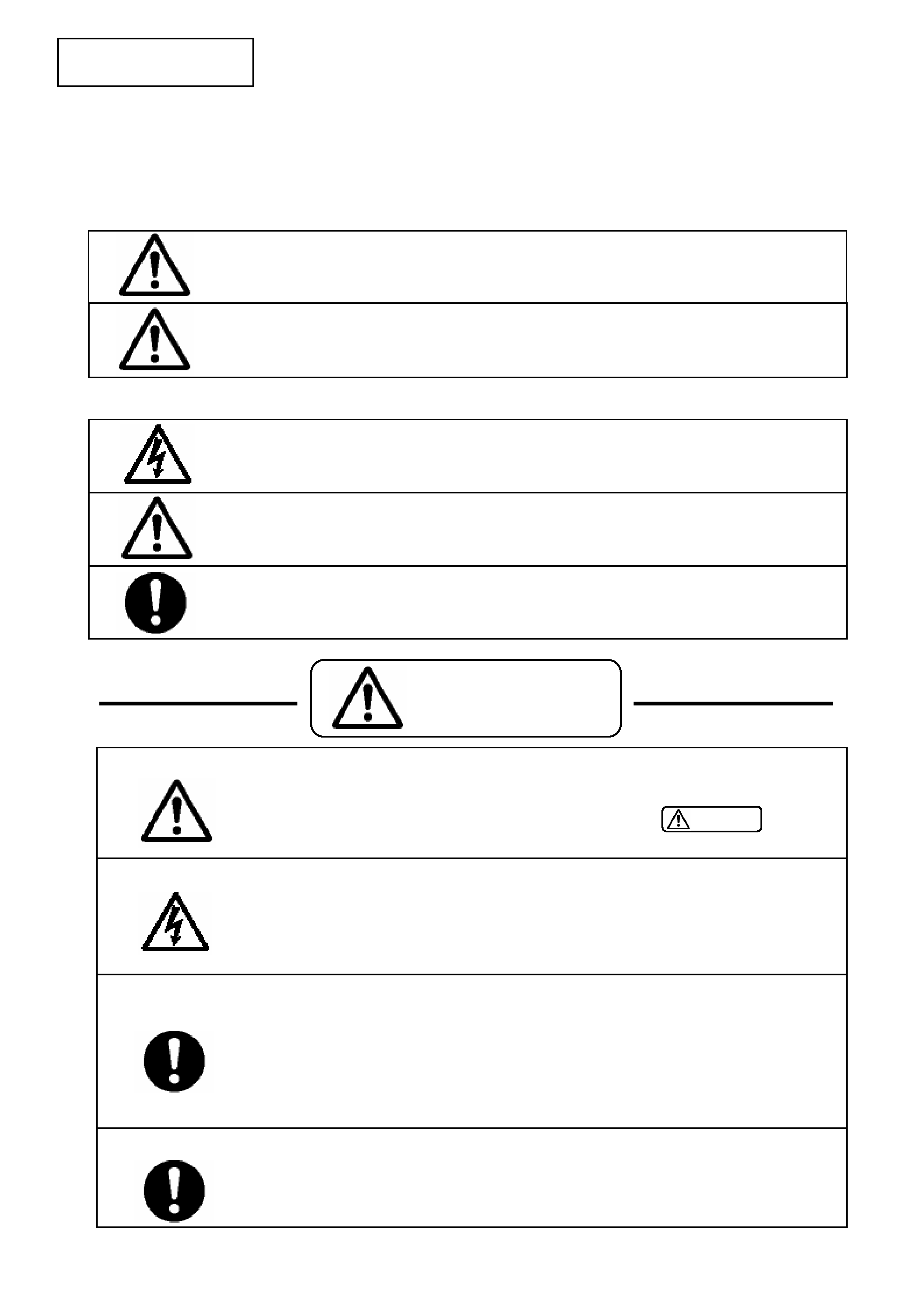
(1) The degree of danger and material damage, caused as a result of wrong use by disregarding the contents
of the display" is distinguished and explained in the table below.
(2) Kinds of the matters to be observed are classified and explained in the icons shown below.
· Be careful of an electric shock or a burn.
· The power block or the PDP module involves the sections where high voltage or high
temperature is prevalent. When equipment is energized, use working gloves in order to
prevent an electric shock or a burn. At the time of transportation, disassembly,
reassembly, and the replacement of parts, such a servicing job must be done after pulling
out the power plug.
If this display is disregarded and equipment is handled
wrongly, this can be a cause of physical injury and a
fire, thus leading a person to death or serious injury.
If this display is disregarded and equipment is
handled wrongly, this may lead to personal injury or
material damage.
This icon indicates the contents of "caution" that must be borne in mind, without fail.
This icon indicates the contents of "caution" that must be practiced, without fail.
This icon indicates a dangerous place where an electric shock is anticipated.
· The replaced parts and wiring must be arranged in the original conditions.
· For safety reasons, insulation materials like tubes and tapes may be used or some parts
may be mounted clear of the PWB. The internal wiring and the fastening with the
clampers for separation from high-heat and high-voltage parts shall be returned to their
original conditions, without fail.
· Modification of equipment is absolutely prohibited. Use the specified parts at all times.
· If any modification is performed, the validity of the manufacturer's warranty is lost at that
moment. The personnel who did this modification is responsible for the physical injury or
the like, if it should occur as a result of the modification. The parts used are given the
safety-based characteristics, such as non-flammability or sufficient withstand voltage. The
parts to be replaced shall be those which are specified in the list of replacement
parts.(Example: The lithium battery (circuit symbol BA9501 in the MAIN PWB) will give
rise to explosion if its polarity is wrongly treated.
· Observe the caution matter, without fail.
· In the place where a particular caution is needed during maintenance servicing, such a
caution note is displayed with a label or a stamp that is given to the cabinet, chassis,
PWB, etc. These caution notes and also the caution matters of
given in
the instruction manuals, etc., must be observed, without fail.
WARNING
CAUTION
WARNING
WARNING
SERVICE SAFETY
2-1