MITSUBISHI DIGITAL ELECTRONICS AMERICA, INC.
9351 Jeronimo Road, Irvine, CA 92618-1904
Copyright © 2004 Mitsubishi Digital Electronics America, Inc.
All Rights Reserved
CAUTION:
Before servicing this chassis, it is important that the service person read the "SAFETY PRECAUTIONS" and
"PRODUCT SAFETY NOTICE" contained in this manual.
MITSUBISHIELECTRIC
Service
Manual
2003
· Weight and dimensions shown are approximate.
· Design specifications are subject to change without notice.
PLASMA DISPLAY PANEL
SPECIFICATIONS
· Power
: AC 120V, 50/60Hz
540W (Typical)
6.7A (Maximum)
· Signals
Sync Range
: Horiz : 15.5 to 110kHz
(Automatic : step scan)
: Vert : 50.0 to 120 Hz
(Automatic : step scan)
Input Signals
: RGB, HD*1,
DVD*1, DTV*1
· Input Terminals
RGB
: Visual 1 (Analog) : Mini D-sub 15-pin
Visual 2 (Analog) : BNC (R,G,B,H/CS,V)*2
Visual 3 (M-LINK) : MONITORLINKTM (DVI)
Video
: Visual 1 : BNC
Visual 2 : RCA-pin
Visual 3 : S-Video: DIN 4-pin
DVD/HD/DTV
: Visual 1 RCA-pin (Y,PB[CB},PR{CR])*1
Visual 2 BNC (Y,PB[CB},PR{CR])*1*
Audio
: Stereo RCA x 3 (Selectable)
External Control
: D-sub 9-pin (RS232C)
· Sound Output : 9W+9W at 6 ohms
· Dimensions
: (W)57.9" (H)34.7" (D)4.7"
(W)1470 (H)880 (D)119 mm
· Weight
: 134.5 lbs / 61 kg
PD-6130
*1 HD/DVD/DTV Input Signa ls supporte d:
480P (60Hz)
480I (60Hz)
525P (60Hz)
525I (60Hz)
576P (50Hz)
576I (50Hz)
625P (50Hz)
625I (50Hz)
720P (60Hz)
1035I (60Hz)
1080I (50Hz)
1080I (60Hz)
*2 The 5-BNC conne ctors are used as
RGB/P C2 a nd HD/DV D2 input.
S e le ct one of the m unde r "BNC S ELECT".

CONTENTS
SERVICE SAFETY ............................................................................................................................................ 2-1
TROUBLESHOOTING ....................................................................................................................................... 3-1
METHOD OF ADJUSTMENTS .......................................................................................................................... 4-1
METHOD OF DISASSEMBLY ........................................................................................................................... 5-1
PART LIST ......................................................................................................................................................... 6-1
CONNECTION DIAGRAMS ............................................................................................................................... 7-1
BLOCK DIAGRAMS ........................................................................................................................................... 8-1
1-1
2-1
SAFETY SERVICE
s Safety cautions
The matters to be observed without fail are explained below. These matters are indispensable for the prevention
of an accident during the maintenance servicing, the "security of products" after the completion of servicing
work, and the "prevention of the repeated occurrence of similar fault."
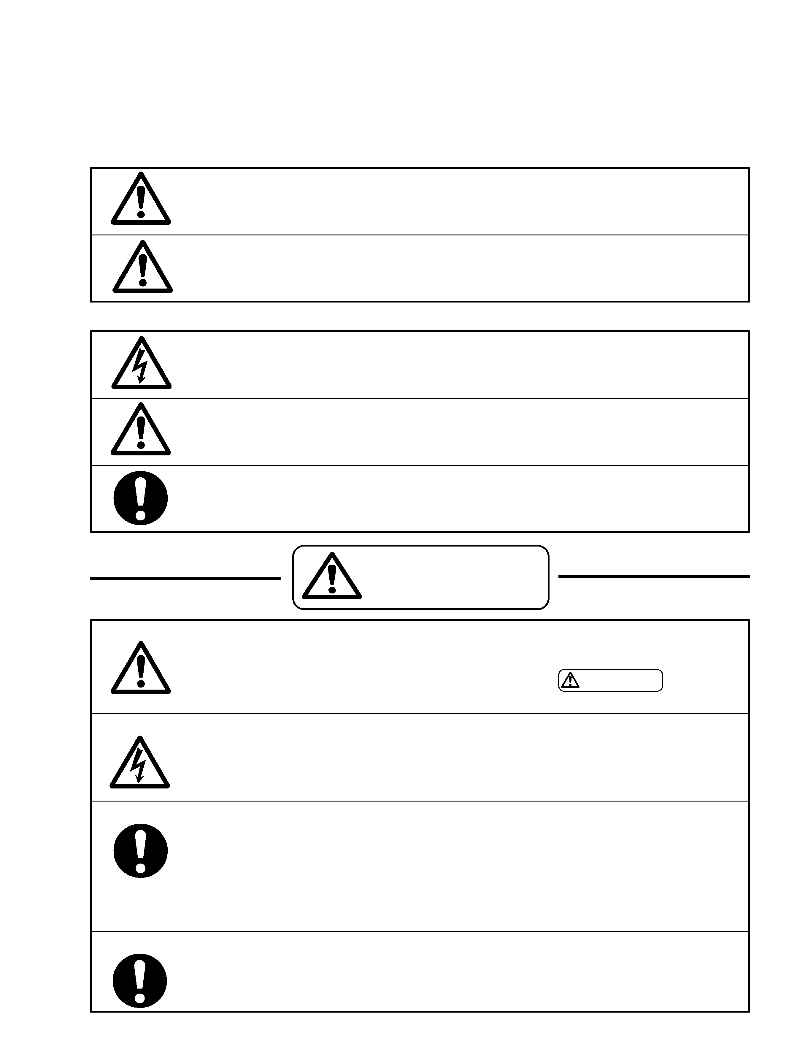
(1) The degree of danger and material damage, caused as a result of wrong use by disregarding the contents
of the display" is distinguished and explained in the table below.
If this display is disregarded and equipment is handled wrongly,
this can be a cause of physical injury and a fire, thus leading a
person to death or serious injury.
If this display is disregarded and equipment is handled wrongly,
this may lead to personal injury or material damage.
(2)
Kinds of the matters to be observed are classified and explained in the icons shown below.
This icon indicates a dangerous place where an electric shock is anticipated.
This icon indicates the contents of "caution" that must be borne in mind, without fail.
This icon indicates the contents of "caution" that must be practiced, without fail.
WARNING
CAUTION
WARNING
· Observe the caution matter, without fail.
·
In the place where a particular caution is needed during maintenance servicing, such a
caution note is displayed with a label or a stamp that is given to the cabinet, chassis, PWB,
etc. These caution notes and also the caution matters of
WARNING given in the
instruction manuals, etc., must be observed, without fail.
· Be careful of an electric shock or a burn.
·
The power block or the PDP module involves the sections where high voltage or high tem-
perature is prevalent. When equipment is energized, use working gloves in order to prevent
an electric shock or a burn. At the time of transportation, disassembly, reassembly, and the
replacement of parts, such a servicing job must be done after pulling out the power plug.
· Modification of equipment is absolutely prohibited. Use the specified parts at all times.
·
If any modification is performed, the validity of the manufacturer's warranty is lost at that
moment. The personnel who did this modification is responsible for the physical injury or
the like, if it should occur as a result of the modification. The parts used are given the
safety-based characteristics, such as non-flammability or sufficient withstand voltage. The
parts to be replaced shall be those which are specified in the list of replacement
parts.(Example: The lithium battery (circuit symbol BA9501 in the MAIN PWB) will give
rise to explosion if its polarity is wrongly treated.
· The replaced parts and wiring must be arranged in the original conditions.
·
For safety reasons, insulation materials like tubes and tapes may be used or some parts
may be mounted clear of the PWB. The internal wiring and the fastening with the clampers
for separation from high-heat and high-voltage parts shall be returned to their original
conditions, without fail.

2-2
· For the maintenance servicing, safety inspection is needed in accordance with the check list.
·
Inspection should be carried out according to the check list shown below, in regard to
safety inspection before and after repairing, authentic repair, and explanation to the user.
(Method of insulation check)
Mount a PDP module on the product to complete it. After the completion of aging and
others, pull out the power plug from the wall outlet, remove the cable, and turn on the
power switch. Use a 500V megger (Note 1) and confirm that the insulation resistance is
500M
or more between each terminal (except for the 3-core earth terminal) of the power
plug (Note 2) and the external exposed metallic parts (Note 3). If the insulation resistance
is found to be below the specified value, recover the faulty section and make another
insulation check again.
(Note 1) If a 500V megger is not available at that time, use a circuit tester or the like.
(Note 2) In the case of a 3-core terminal, the earth resistance shall be 1
or less between the earth
terminal and the earth side of each input terminal.
(Note 3) Head phone jack, speaker terminals, remote control terminals, each I/O terminals, control termi-
nals, screws, etc.
Check item
Check column
Safety
inspection
before
repairing
Installation
conditions
Is there any influence by high temperatures (due to direct sunlight, etc.), moisture (steam, etc.), oil
fume, dust, and dew condensation?
Is the condition of ventilation acceptable (distance to the wall, ventilation holes, etc.)?
Is the condition of the antenna acceptable (reach to the wire, bend, tilt, etc.)?
Is the condition of power supply acceptable (regular outlet, adequate earthing, concentrated wiring, etc.)?
Is the condition of installation acceptable (unstability, height, tilt, falling preventive materials, etc.)?
Are the power plug and the power cord free from damage or the attachment of dust?
Is the product free from unusual sound, unusual odor, or unusually high temperature?
Are the knobs, handles, and back cabinet free from abnormality (rattling, drop off, etc)?
Is equipment free from any abnormality in daily use?
Is the symptom examined according to the user's statement?
Is the product disassembled to the grade where troubleshooting is possible?
Is the symptom reproduced, the faulty part located as a result of fault diagnosis, and replaced?
Is the normal condition confirmed after aging?
Is the part, specified in the list of parts, used for the power unit?
Is the part, specified in the list of parts, used for the insulation material (material, thickness, etc)?
Is the part, specified in the list of parts, used for the power plug and the power cord?
Is the part, specified in the list of parts, used for the internal cabling and the high voltage lead wires?
Is the part, specified in the list of parts, used for the PDP module?
Are the rest of replaced parts those specified in the list of parts?
Is the part version correct?
Are the part mounting position, fixing method, and the distance the same as those of original?
Is the wiring layout the same as the original (connector, clamper, distance from a heat generating part, etc)?
Is the soldering condition acceptable (whisker, too much solder, tunnel, failure in winding, etc)?
Is the insulation material the same as the original (tubes, tapes, fiber, etc.)?
Product
main
body
Authentic
repair
T
rouble-
shooting
Specified
parts
Wires
mounted
Are the repaired section and its peripheral parts free from abnormality?
Is there any intrusion of foreign substances (solder chips, wire chips, screw chips, screws, etc.)?
Is everything free from danger due to deterioration (discoloration, damage, leakage, etc.)?
Is the safety protection circuit in normal operation?
Are contamination and dust removed after final finish?
Is there any failure in mounting and tightening (back cabinet, falling preventive materials, etc.)?
Is there any influence by high temperatures (direct sunlight, stove, etc.), moisture (steam, etc.), oil fume,
dust, and dew condensation?
Is the condition of ventilation acceptable (distance to the wall, ventilation holes, etc.)?
Is the condition of the antenna acceptable (reach to the wire, bend, tilt, etc.)?
Is the condition of power supply acceptable (regular outlet, adequate earthing, concentrated wiring, etc.)?
Is the condition of installation acceptable (unstability, height, tilt, falling preventive materials, etc.)?
Is the insulation check finished with a circuit tester or the like? (Refer to the above description, "Method of
insulation check.")
Are the contents and actual treatment of repairing and safety inspection services duly explained?
To use equipment after reading through the instruction manual.
Not to dislodge the back cabinet.
Not to insert anything in ventilation holes and clearances.
To pull out the power plug if the product is not used for a long time.
To ask an NEC's authorized maintenance service company for the cleaning of the product interior
for the removal of dust.
To turn off the power switch when cleaning the panel surface and the cabinet.
To turn off the power switch of the main unit for the product provided with a remote control, in case
of going out or sleeping.
Are explanations given to pull out the power plug in case of abnormality and to contact the dealer or an
NEC's authorized maintenance service company.
Safety
inspection
after
repairing
Explanation
to
the
user
Explanation
of
use
2-3
s Miscellaneous caution matters
(1)
This product uses highly integrated semiconductor parts. Since these parts are fragile to electrostatic
charges, earth bands should be used for handling. The product should be handled where measures have
been taken against electrostatic charges.
(2)
For this product, the PDP modules and the PWBs are repaired by replacement in a unit. Therefore, the
units of the PDP modules and the PWBs must not be repaired or disassembled. Otherwise, the validity of
warranty will be lost.
(3)
If this product is used for the fixed character display or the like as in the case of a character display board,
a phenomenon of burning (not warranted) will occur. Burning is a phenomenon that the unevenness in the
brightness is caused in the display. In such a case, the brightness in the section where the integrated
display time is longer becomes lower than the brightness in another section where the integrated display
time is shorter. This phenomenon is in proportion to the integrated display time and the brightness. For this
reason, to relieve this difficulty during servicing, do not use any still picture, but use a display by motion
pictures of a video or the like. In addition, use "FULL" for the screen mode and avoid using any display by
"NORMAL", "TRUE", or MULTI SCREEN like side by side etc. If it is necessary to use only a still picture for
unavoidable reasons, use a burning relief function such as "PLE LOCK", "ORBITER", "SCREEN WIPER",
etc.
(4)
When a PDP module is operated after a long time of storage, it may encounter a difficulty like a failure in
displaying a screen or unstability according to the condition of storage. In such a case, the PDP module
should be incorporated in the product and aging treatment should be carried out for about two hours (all
screen display).
(5)
Sulfides will deteriorate the PDP module and this is a cause of malfunction. Therefore, it is absolutely
prohibited to put any vulcanized rubber or a material containing sulfur in the vicinity of the PDP module.
(6)
When taking out a PDP module from the maintenance package box, do it slowly so that the panel surface
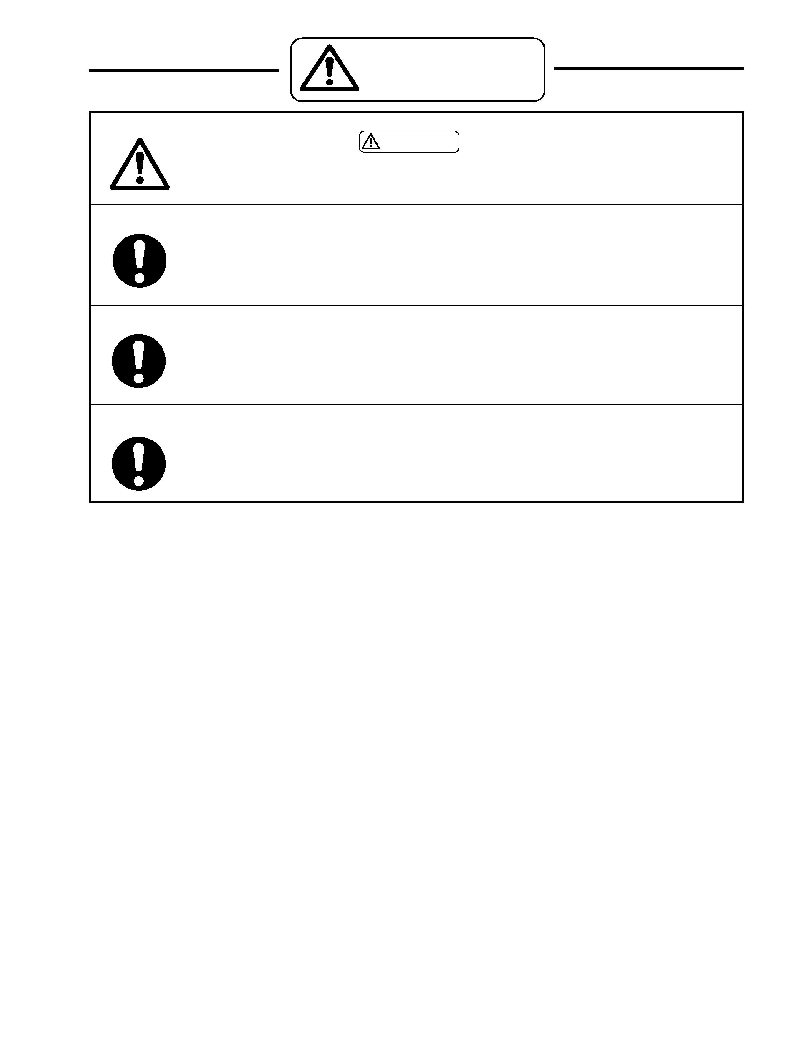
CAUTION
· Observe the caution matter, without fail
·
The caution matters of
CAUTION
given in the instruction manuals, etc., must be
observed, without fail.
· Do not give shocks and vibration.
·
The panel surface (display plane) of the filter and the PDP module is made of glass. If any
shocks or vibration is applied, it may be broken and the scattered glass chips will be a
cause of injury.
· Do not put anything.
·
Do not put anything on the product. Otherwise, this can be a cause of injury as a result of
falling down or dropping caused by imbalance.
· Transportation must be done by enough personnel.
·
The product is heavy. In the case of transportation, unpacking, or packing, more than two
persons should do it (four persons for a product of 50-inch or larger) by supporting the top
and the bottom of the product.