1
MITSUBISHI HS 641 V
E2PROM Initialise &
Service Position
HOW TO INITIALIZE THE E2PROM
A replacement E2PROM is not initialized before
shipping, so the E2PROM must be initialized
when replaced.
Initialize the E2PROM by following the steps
below.
1. Set the VCR to `CLOCK SET' mode.
2. Push COUNTER RESET button on the remote
hand unit for 8 seconds.
3. E2PROM initial setting is completed.
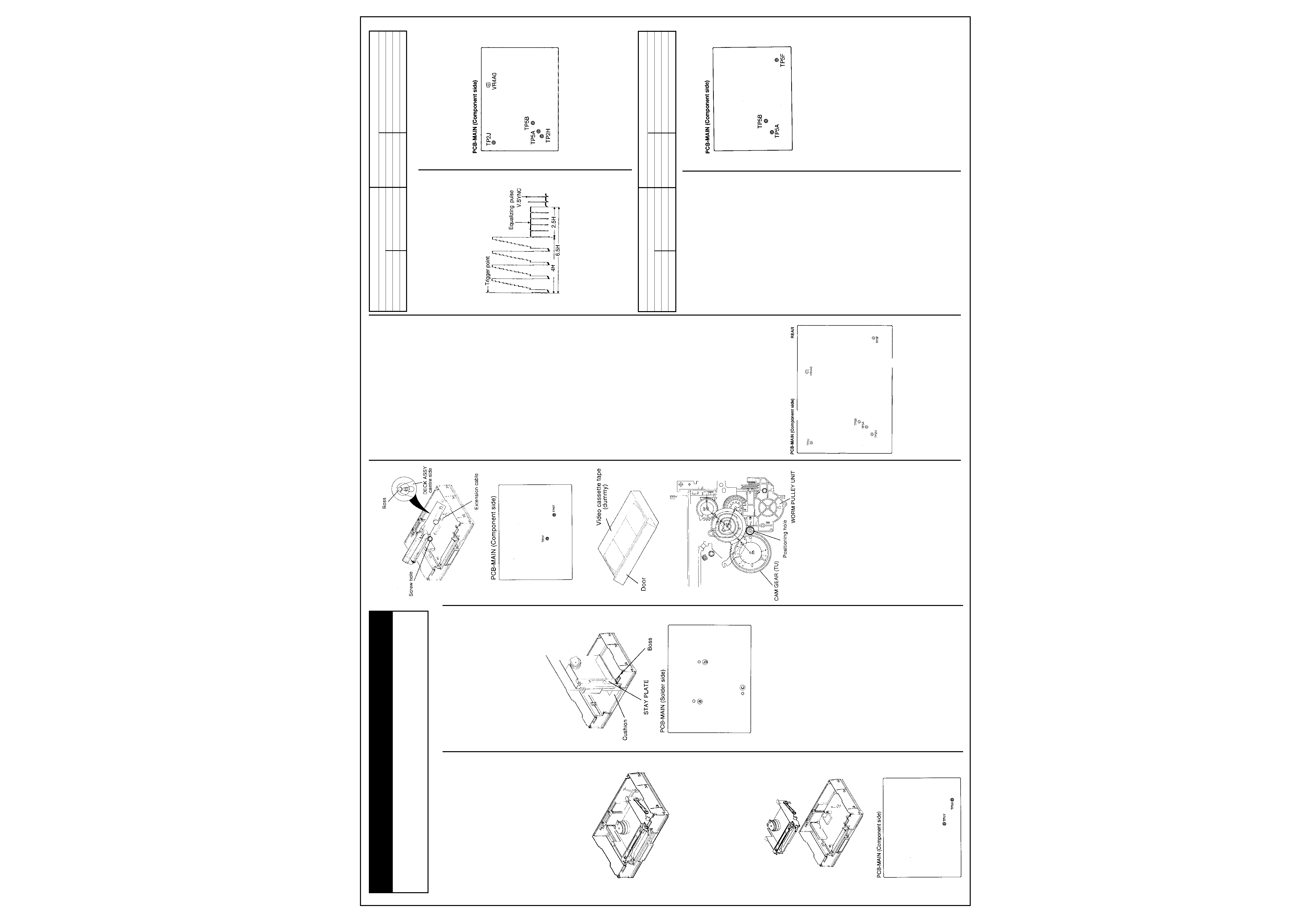
Service Position
Service Position
(A)
Service Item
· Worn parts on the deck (UPPER DRUM ASSY,
PINCH ARM ASSY, A/C HEAD UNIT and FE
HEAD.) can be replaced.
· Checks at test points may be made to isolate a
problem to a specific circuit.
1. Remove the Top Cover and Front Panel.
(Refer to Para. 1 and 2 of the DISASSEM-
BLY.)
Service Position
(B)
Service Item
· Parts on the deck can be replaced.
· Service can be executed with the EE picture
displayed.
1. Remove the DECK ASSY. (Refer to Para. 4 of
the DISASSEMBLY.)
2. Connect TP5X and TP5Y via diode (1SS252).
TP5X Anode side TP5Y: Cathode side Note:
Make this connection before turning the
power on.
Service Position
(C)
Service Item
· Operation can be checked in every mode.
· Parts on the copper side of the PCB-MAIN
can be checked and replaced.
1. Remove the DECK ASSY, INSERT GUIDE
and PCB-MAIN. (Refer to Para. 4 and 5 of the
DISASSEMBLY and Para. 1 of the HOW TO
EXECUTE CIRCUIT BOARD SERVICE.)
2. Install the three screws (a), (b) and (c) to
secure the PCB-MAIN and DECK ASSY.
Note: Check the connection of the MC
connector.
3. Rotate the PCB-MAIN and DECK ASSY
upward holding them in position.
4. Connect all connectors on PCB-MAIN.
5. Stand the DECK ASSY and the PCB-MAIN on
the Base chassis so that the hole on the STAY
PLATE (Take up side) of the DECK ASSY
aligns with the boss of the Base chassis.
6. Fix the PCB-MAIN on the Base chassis,
providing a cushion between them for secure
installation.
Deck Operation Check
Fig. 1
Fig. 2
Fig. 3
Fig. 4
Operation of the deck position and tape running
systems can be checked according to the
following method.
1. Unscrew all screws fastening the DECK
ASSY and Shield Case.
2. Place the DECK ASSY on the Base Chassis
so that the centre of the rear side aligns with
the boss and that the rear side of the supply
side aligns with the screw hole as shown in
Fig. 1. Raise the front side of the DECK ASSY
and hold it with a support.
Note: The MODE DETECT SENSOR, START
SENSOR, END SENSOR, REEL SENSOR
and RECORD PROTECTION SENSOR
cannot operate in this state. Parts on the
DECK (LOADING BELT and REEL BELT) can
be replaced.
3. Connect TP5Y and TP5T via diode (1SS252).
TP5T: Anode side
TP5Y: Cathode side
Note: Connect them before plugging in the
set.
4. Turn the power on.
5. Insert the video cassette tape.
Note: This check may damage the cassette
tape. Use a dummy cassette tape with a door
or other tapes for check purpose only.
6. Press the CH-UP and CH-DOWN buttons on
the PCB-MAIN to check the deck position.
CH-UP button : Operation in the loading
direction. CH-DOWN button: Operation in the
unloading direction.
7. Connect the MC connector and the CAPSTAN
MOTOR on the PCB-MAIN with the Extension
cable (859C433080). Press the FF and REW
buttons on the PCB-MAIN to check the
operation of the tape running system.
Note: Take care so that the two connectors of
the Extension cable are attached in the same
direction, without twisting the cable.
FF button: Forward rotation is implemented
REW button: Reverse rotation is implemented
Example: Playback, REW/FF
1) Press the CH-UP or CH-DOWN button to
align the character "PR" or "FR" of the CAM
GEAR (TU) with the positioning hole of the
WORM PULLEY UNIT shown in Fig. 4.
"PR": Playback position
"FR": REW/FF position
2) For fast forward operation check, press the
FF button to make the CAPSTAN MOTOR
rotate in the forward direction. For rewind
operation check, press the REW button to
make the CAPSTAN MOTOR rotate in the
reverse direction.
Electrical Adjustments
Perform only the alignments required. If proper
equipment is not availabledo not attempt an
alignment.
PRE-ADJUSTMENT SETTINGS
· Set the "COLOUR SYSTEM" to "PAL" mode in
the MENU. (HS-640V(E), (G)/HS-640(Y) only)
· Set the "TAPE OPTIMIZER" to "OFF" mode in
the MENU.
· Set the "BAND-OPTIMIERUNG" to "OFF"
mode in the MENU. (HS-640V(G) only)
· Set the "RENTAL PB" to "OFF" position.
MEASURING EQUIPMENT
· Oscilloscope (10:1 probe unless 1:1 speci-
fied.)
· Frequency counter
· Electrical tools
LOCATIONS
[Servo circuit]
1 Playback Switching Point
Adjustment purpose
Video switch over timing during playback.
Symptom when incorrectly adjusted
Switching noise or jitter in the playback picture.
1. Playback an alignment tape (PS2, stair step).
2. Short-circuit TP5A to TP5B. Confirm that the
"D" displayed in Fluorescent Display flashes
fast.
3. Observe the waveform at TP2J.
4. Set the oscilloscope's slope to (--).
5. Adjust VR4A0 so that the trigger point is
located at 6.5
±1.0H before the vertical
synchronizing signal.
[Timer circuit]
2. Clock Frequency Correction
Adjustment purpose
To set the accuracy of clock.
Symptom when incorrectly adjusted
Poor clock accuracy.
1. Set the VCR to POWER off. (With the tape
ejected from VCR.)
2. Short-circuit TP5A to TP5B.
3. Observe the frequency at TP5F.
4. Be certain that the frequency is between
262.1000 262.1882kHz.
5. Use the number buttons on the remote hand
unit to enter the last three digits of the
frequency counter reading
(262.1(a)(b)(c)kHz). (Confirm that the "." is
not displayed in fluorescent display.) Enter
the digits in (a)(b)(c) sequence.
6. Push the REC button on the remote hand
unit. (Confirm that the "." is displayed in
fluorescent display.)
7. Open-circuit TP5A to TP5B.
Mechanical Adjustments
and Replacements
1.Cleaning the DECK
The following parts require cleaning whenever
serviced to maintain satisfactory performance.
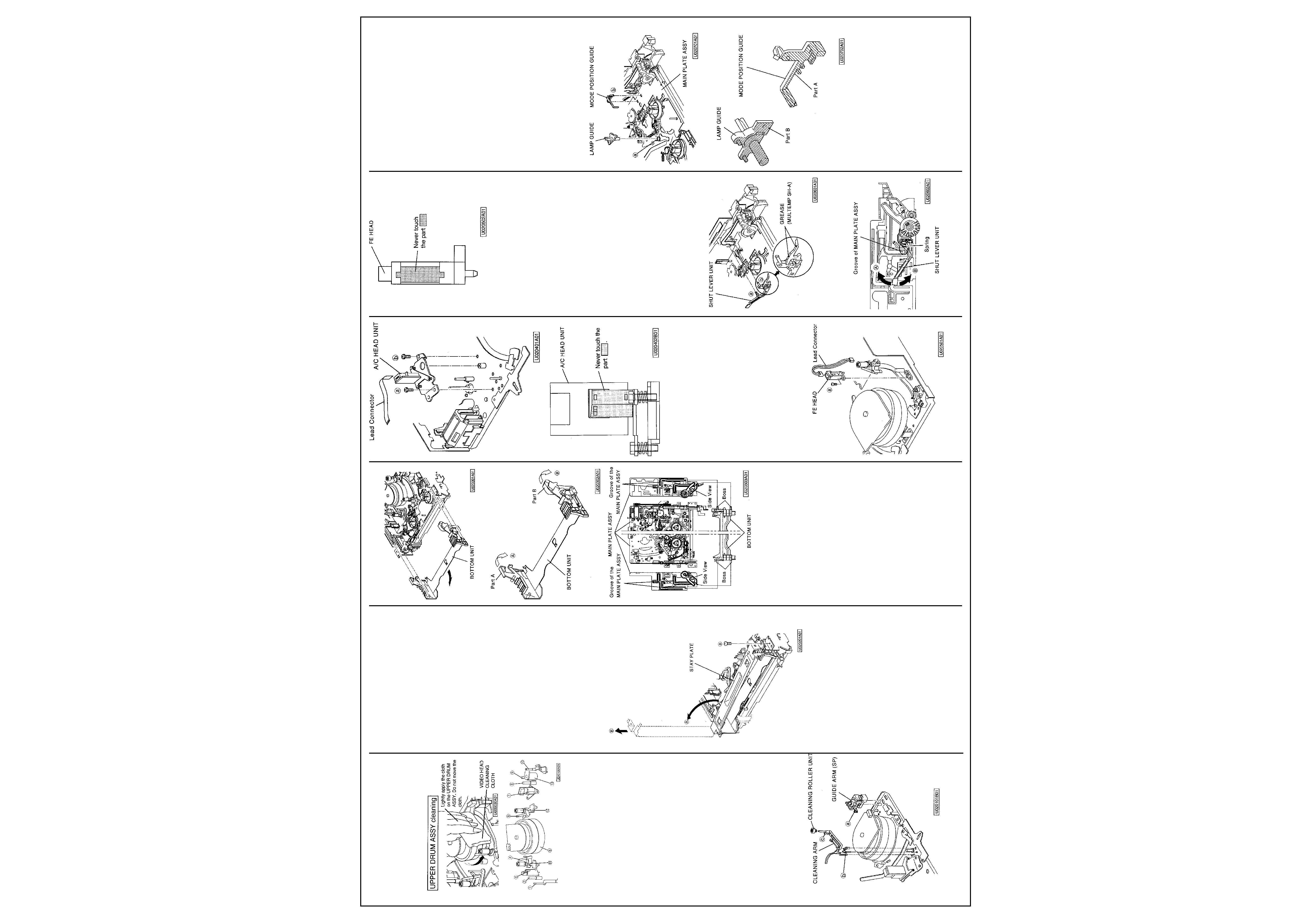
1-1 VIDEO HEAD
1. Clean the VIDEO HEADs by the following
method. Dust and other foreign objects on the
VIDEO HEADs disturb the normal playback
picture. Dampen a VIDEO HEAD CLEANING
CLOTH with alcohol. Hold the cloth against
the DRUM and slowly turn the DRUM
counterclockwise to clean.
Note: Do not directly touch the HEAD
attached to the UPPER DRUM ASSY. The
HEAD is very hard but brittle to impact,
especially in the vertical direction. Do not
apply force in the vertical direction.
General Information
Also Covers
U Deck HS 640 V
Measuring instrument and condition.
VCR set up condition
Oscilloscope
Input signal
------
Test point
TP2J
Using tape
Alignment tape (PS2, stair step)
EXT trigger
TP2H
VCR condition
Playback
Measurement range
DIV 20mV TIM 50
µs
Using Jig
------
Measuring instrument and condition.
VCR set up condition
Frequency CVounter
Input signal
------
Test point
TP5F
Using tape
------
EXT trigger
------
VCR condition
POWER off
Measurement range
------
Using Jig
------
2. Allow residual alcohol to dry thoroughly before
running a tape. Otherwise, the liquid may stick
to and damage the tape.
1-2 Tape Transport
(Refer to Fig. 1-1, next page)
Clean the following parts of the Tape transport.
1. TENSION PIN
2. GUIDE POLE (SP)
3. FE HEAD
4. SLANT POLE (SP)
5. UPPER/LOWER DRUM ASSY
6. SLANT POLE (TU)
7. A/C HEAD
8. GUIDE POLE (TU)
9. CAPSTAN SHAFT
10.GUIDE PIN (TU)
2
MITSUBISHI HS 641 V
Mechanical Adjustments
and Replacements Cont'd
11. GUIDE ROLLER (SP)
12. GUIDE ROLLER (TU)
13. PINCH ROLLER
Fig. 1-1
1. Clean the tape transport using gauze
dampened with alcohol, except the GUIDE
ROLLER (SP), GUIDE ROLLER (TU) and
PINCH ROLLER for which dry gauze
should be used.
2. Allow residual alcohol to dry thoroughly
before running a tape. Otherwise the liquid
may stick to and damage the tape.
1-3 REEL DISK Drive System
1. Clean the REEL DISK braking surfaces and
the REEL BELT.
2. Clean the REEL DISK drive system using
gauze dampened with alcohol, except the
REEL BELT for which dry gauze shall be
used.
3. Allow residual alcohol to dry thoroughly
before operation.
2. Replacement of Major Parts
2-1 GUIDE ARM (SP), CLEANING ARM,
CLEANING ROLLER UNIT
Position the set normally.
(Removal)
1. Disconnect the lead from the FE HEAD,
which is clamped on the GUIDE ARM (SP)
shown in Fig. 2-1-1.
Fig. 2-1-1
2. Unfasten the catch (a) of the GUIDE ARM
(SP) shown in Fig. 2-1-1 to remove the
GUIDE ARM (SP).
3. Unfasten the catch (b) of the CLEANING
ARM shown in Fig. 2-1-1 to remove the
CLEANING ARM.
4. Unfasten the catch (c) of the CLEANING ARM
shown in Fig. 2-1-1 to remove the CLEANING
ROLLER UNIT from the CLEANING ARM.
(Installation)
1. Install the CLEANING ROLLER UNIT shown
in Fig. 2-1-1 to the CLEANING ARM.
2. Install the CLEANING ARM shown in Fig. 2-1-
1.
3. Install the GUIDE ARM (SP) shown in Fig. 2-
1-1.
4. Connect the lead from the FE HEAD.
2-2 STAY PLATE
Position the set normally.
(Removal)
1. Unfasten the STAY PLATE fastening screw
(a) shown in Fig. 2-2-1.
2. Raise the STAY PLATE in the direction shown
by arrow (A) so that it stands completely in
vertical as shown in Fig. 2-2-1. Remove the
STAY PLATE in the direction shown by arrow
(B).
(Installation)
1 Install the STAY PLATE shown in Fig. 2-2-1.
Fig. 2-2-1
2-3 BOTTOM UNIT
Position the set normally.
(Removal)
1. Remove the STAY PLATE. (Refer to Para. 2-2.)
2. Remove the BOTTOM UNIT in the direction
shown by the arrow as shown in Fig. 2-3-1.
(Installation)
1. Move the part A of the BOTTOM UNIT in the
direction shown by arrow (A) and hold it with
your hand as shown in Fig. 2-3-2. (You can
install the BOTTOM UNIT without holding the
part A, if a cassette tape is loaded in the
BOTTOM UNIT.)
2. Move the part B of the BOTTOM UNIT in the
direction shown by arrow as shown in Fig. 2-
3-2.
3. Install the BOTTOM UNIT so that its boss
matches with the groove of the MAIN PLATE
ASSY as shown in Fig. 2-3-3.
4. Install the STAY PLATE. (Refer to Para. 2-2.)
Fig. 2-3-1
Fig. 2-3-2
Fig. 2-3-3
2-4 A/C HEAD UNIT
Position the set normally.
(Removal)
1 Disconnect the lead connector of the A/C
HEAD UNIT shown in Fig. 2-4-1.
2 Unscrew the two A/C HEAD UNIT fastening
screws ((a) and (b) to remove the A/C HEAD
UNIT.
(Installation)
1 Install the A/C HEAD UNIT shown in Fig. 2-4-
1 Note: Never touch the part shown in Fig. 2-
4-2. If it
is stained, clean it with alcohol.
2 Connect the lead connector of the A/C HEAD
UNIT shown in Fig. 2-4-1.
3 Perform "Adjustment of A/C HEAD" in Para.
3-3 and "Adjustment of Phase" in Para. 3-4 of
"Interchangeability Adjustment of the Mecha-
nism
Fig. 2-4-1
Fig. 2-4-2
2-5 FE HEAD
Position the set normally.
(Removal)
1 Disconnect the lead connector of the FE
HEAD shown in Fig. 2-5-1.
2 Unscrew the FE HEAD fastening screw (®) to
remove the FE HEAD.
(Installation)
1 Install the FE HEAD shown in Fig. 2-5-1.
Note: Never touch the part shown in Fig. 2-5-
2. If it is stained, clean it with alcohol.
2 Connect the lead connector of the FE HEAD
shown in Fig. 2-5-1.
Fig. 2-5-1
Fig. 2-5-2
2-6 SHUT LEVER UNIT
Position the set normally.
Before performing replacement in this para-
graph, remove the following parts. Refer to the
applicable paragraph for installation of each
part.
· STAY PLATE (Para. 2-2)
· BOTTOM UNIT (Para. 2-3)
(Removal)
1 Unfasten the two catches ((a) and (b) of the
SHUT LEVER UNIT shown in Fig. 2-6-1 to
remove the SHUT LEVER UNIT.
(Installation)
1 Apply GREASE (MULTEMP SH-A)
[859D055080] to the area specified in Fig. 2-
6-1 on the new SHUT LEVER UNIT.
2 Install the SHUT LEVER UNIT shown in Fig.
2-6-1.
3 Insert the spring of the SHUT LEVER UNIT
under groove of the MAIN PLATE ASS shown
in Fig. 2-6-2.
4 Make sure that the SHUT LEVER UNIT
returns in the direction shown by arrow ©
when it is moved in the direction shown by
arrow
Fig. 2-6-1
Fig. 2-6-2
2-7 LAMP GUIDE, MODE POSITION GUIDE
Position the set normally.
(Removal)
1 Unfasten the catch (a) of the MAIN PLATE
ASSY shown in Fig. 2-7-1 to remove the
LAMP GUIDE.
2 Unfasten the catch (b) of the MODE POSI-
TION GUIDE shown in Fig. 2-7-1 to remove
the MODE POSITION GUIDE.
(Installation)
1 Clean the part A of the MODE POSITION
GUIDE shown in Fig. 2-7-2 with the VIDEO
HEAD CLEANING CLOTH.
Note: Never use alcohol or equivalent
solvent.
2 Install the MODE POSITION GUIDE shown in
Fig. 2-7-1.
3 Clean the part B of the LAMP GUIDE shown
in Fig. 2-7-2 with the VIDEO HEAD CLEAN-
ING CLOTH.
Note: Never use alcohol or equivalent
solvent.
4 Install the LAMP GUIDE shown in Fig. 2-7-1.
5 After installing the LAMP GUIDE and MODE
POSITION GUIDE, clean the surface of them
with the VIDEO HEAD CLEANING CLOTH.
Note: Never use alcohol or equivalent
solvent.
Fig. 2-7-1
Fig. 2-7-2
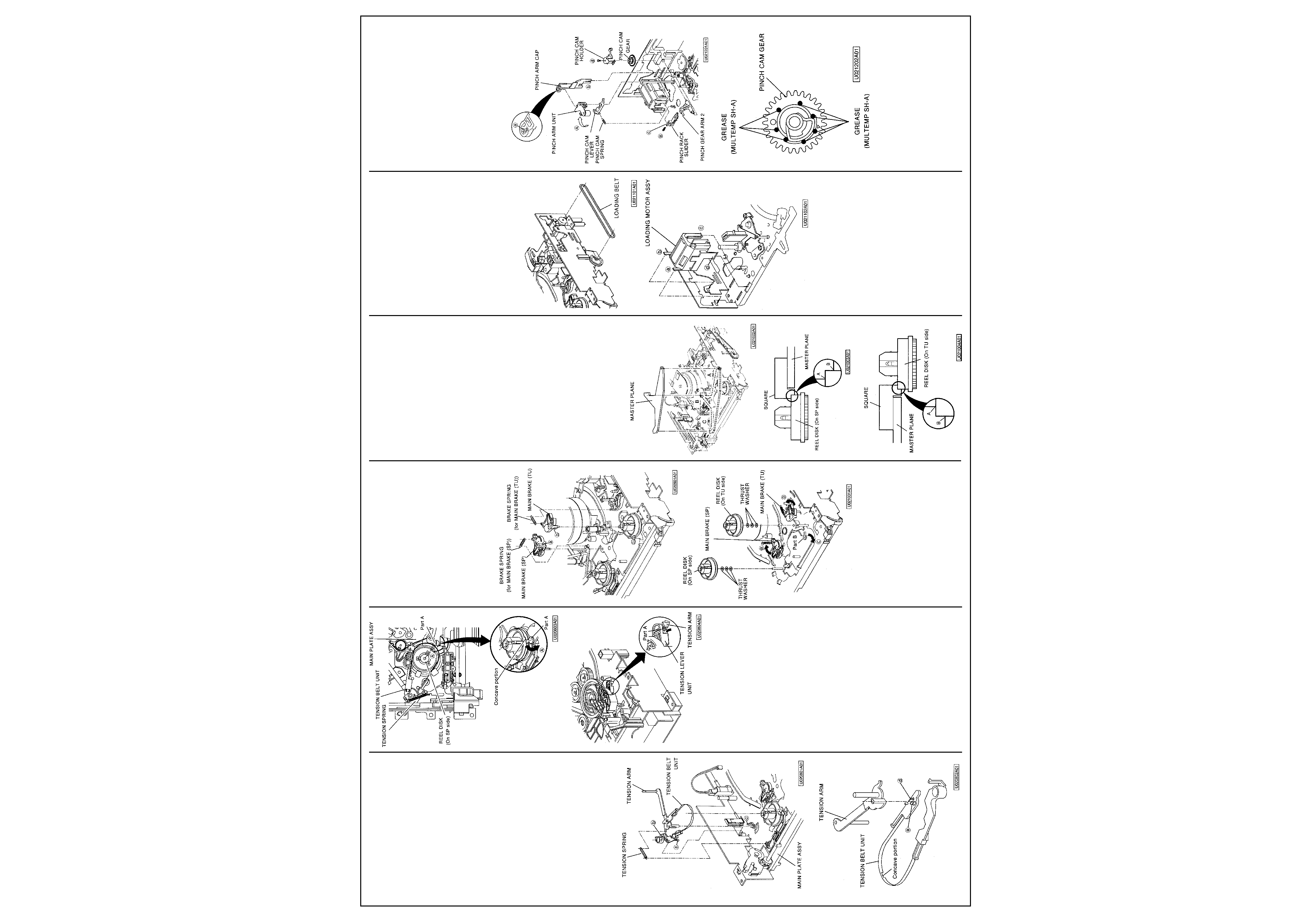
2-8 TENSION SPRING, TENSION ARM,
TENSION BELT UNIT
Position the set normally.
(Removal)
1 Remove the TENSION SPRING shown in Fig.
2-8-1.
2 Move the part A of the MAIN PLATE ASSY
shown in Fig 2-8-3 in the direction shown by
arrow with a minus driver, etc.
3 Unfasten the two catches (a) and (b) of the
TENSION BELT UNIT shown in Fig. 2-8-1.
Unfasten the catch (c) of the MAIN PLATE
ASSY.
3
MITSUBISHI HS 641 V
Mechanical Adjustments
and Replacements Cont'd
Remove the TENSION BELT UNIT with the
TENSION ARM attached.
4 Unfasten the two catches (d) and (e) of the
TENSION BELT UNIT shown in Fig. 2-8-2 to
remove the TENSION ARM.
(Installation)
1 Attach the TENSION ARM on the TENSION
BELT UNIT shown in Fig. 2-8-2.
2 Fasten the TENSION BELT UNIT around the
part shown in Fig. 2-8-3 of the REEL DISK
(On SP side).
Note: Take care never to make GREASE or
OIL adhere to the TENSION BELT UNIT
during installation.
3 Move the part A of the spring of the TENSION
LEVER UNIT shown in Fig. 2-8-4 in the
direction shown by the arrow and install the
TENSION ARM on the position shown in Fig.
2-8-4.
4 Move the part A of the MAIN PLATE ASSY in
the opposite direction of arrow ® to let it enter
the concave portion of the TENSION BELT
UNIT as shown in Fig. 2-8-3 so that it points
to the centre of the REEL DISK (On SP side).
5 Install the TENSION SPRING shown in Fig.
2-8-1.
6 Perform "Adjustment of BACK TENSION and
TENSION PIN Position" in Para. 3-1 of
"Interchangeability Adjustment of the Mecha-
nism".
Fig. 2-8-1
Fig. 2-8-2
Fig. 2-8-3
Fig. 2-8-4
2-9 BRAKE SPRING (for MAIN BRAKE (SP)),
MAIN BRAKE (SP), BRAKE SPRING (for
MAIN BRAKE (TU)), MAIN BRAKE (TU)
Position the set normally.
(Removal)
1 Remove the BRAKE SPRING (for MAIN
BRAKE (SP)) shown in Fig. 2-9-1.
2 Unfasten the catch (a) of the MAIN BRAKE
(SP) shown in Fig. 2-9-1 with tweezers, etc. to
remove the MAIN BRAKE (SP).
3 Remove the BRAKE SPRING (for MAIN
BRAKE (TU)) shown in Fig. 2-9-1.
4 Unfasten the catch (b) of the MAIN BRAKE
(TU) shown in Fig. 2-9-1 to remove the MAIN
BRAKE (TU).
(Installation)
1 Install the MAIN BRAKE (TU) shown in Fig. 2-
9-1.
2 Install the BRAKE SPRING (for MAIN BRAKE
(TU)) shown in Fig. 2-9-1.
3 Install the MAIN BRAKE (SP) shown in Fig. 2-
9-1.
4 Install the BRAKE SPRING (for MAIN BRAKE
(SP)) shown in Fig. 2-9-1.
2-10 REEL DISK (On SP side), REEL DISK
(On TU side)
Position the set normally.
Before performing replacement in this para-
graph, remove the following parts. Refer to the
applicable paragraph for installation of each
part.
· TENSION SPRING (Para. 2-8)
· TENSION ARM (Para. 2-8)
· TENSION BELT UNIT (Para. 2-8)
(Removal)
1 Move the MAIN BRAKE (SP) in the direction
shown by arrow (B) hold it in that state.
Remove the REEL DISK (On SP side) as
shown in Fig. 2-10-1.
2 Move the part B in the direction shown by
arrow (C) with a minus screw driver as shown
in Fig. 2-10-1.
3 Move the BAKE MAIN (TU) in the direction
shown by arrow (D) hold it in that state.
Remove the REEL DISK (On TU side) as
shown in Fig. 2-10-1.
Fig. 2-9-1
Fig. 2-10-1
(Installation)
1 Install the REEL DISK (On SP side) shown in
Fig. 2-10-1.
2 Place the height adjustment jig [MASTER
PLANE] (859C342020) shown in Fig. 2-10-2
in the reference position. (Place the MASTER
PLANE so that the points A, B and C of the
MAIN PLATE ASSY support it.)
3 Place the height adjustment jig [SQUARE]
(859C433060) shown in Fig. 2-10-2 on the
MASTER PLANE. Move it to the position
shown in Fig. 2-10-3 to make sure that A can
pass but B cannot pass under the REEL DISK
(On SP side).
4 If the height of the REEL DISK (On SP side)
is not correct, adjust it to the height specified
in Item 3 by removing or adding the THRUST
WASHER to be fixed to the shaft under the
REEL DISK (On SP side).
· If it is high, remove THRUST WASHER.
· If it is low, add THRUST WASHER.
5 Install the TENSION BELT UNIT, TENSION
ARM and TENSION SPRING. (Refer to Para.
2-8 for the installation method.)
6 Make sure that the REEL DISK (On SP side)
shown in Fig. 2-10-1 cannot come off.
7 Install the REEL DISK (On TU side) shown in
Fig. 2-10-1.
8 Place the height adjustment jig [MASTER
PLANE] (859C342020) shown in Fig. 2-10-2
in the reference position. (Place the MASTER
PLANE so that the points A, B and C of the
MAIN PLATE ASSY support it.)
9 Place the height adjustment jig [SQUARE]
(859C433060) shown in Fig. 2-1 0-2 on the
MASTER PLANE. Move it to the position
shown in Fig. 2-10-4 to make sure that A can
pass but B cannot
pass under the REEL DISK (On TU side).
10If the height of the REEL DISK (On TU side) is
not correct, adjust it to the height specified in
Item 9 by remove or adding the THRUST
WASHER to be fixed to the shaft under the
REEL DISK (On TU side).
· If it is high, remove THRUST WASHER.
· If it is low, add THRUST WASHER.
11Move the part of the MAIN PLATE ASSY in
the opposite direction of arrow (C) as shown
in Fig. 2-10-4 so that it points to the centre of
the REEL DISK (On TU side).
12Make sure that the REEL DISK (On TU side)
shown in Fig. 2-10-1 cannot come off.
Fig. 2-10-2
Fig. 2-10-3
Fig. 2-10-4
2-11 LOADING BELT, LOADING MOTOR
ASSY
Position the set normally.
(Removal)
1 Remove the LOADING BELT shown in Fig. 2-
11-1.
2 Unfasten the two catches (A) and (B) of the
LOADING MOTOR ASSY shown in Fig. 2-11-
2 and the two catches (c) and (d) of it shown
in Fig. 2-11-2 to remove the LOADING
MOTOR ASSY.
(Installation)
1 Install the LOADING MOTOR ASSY shown in
Fig. 2-11-2.
2 Fasten the LOADING BELT shown in Fig. 2-1
1-1.
Note: Take care never to make GREASE or
OIL adhere to the LOADING BELT during
installation.
Fig. 2-11-1
Fig. 2-11-2
2-12 PINCH ARM CAP,
PINCH ARM UNIT,
PINCH GEAR ARM 2,
PINCH CAM HOLDER,
PINCH CAM SPRING,
PINCH CAM LEVER,
PINCH RACK SLIDER,
PINCH CAM GEAR
Position the set normally.
(Removal)
1 Unfasten the two catches (a) and (b) of the
PINCH ARM CAP shown in Fig. 2-12-1 with
the tweezers, etc. to remove the PINCH ARM
CAP.
2 Move the PINCH ARM UNIT in the direction
shown by arrow (A) to remove it as shown in
Fig. 2-12-1.
3 Remove the PINCH GEAR ARM 2 shown in
Fig. 2-12-1.
4 Remove the PINCH CAM SPRING shown in
Fig. 2-12-1.
5 Remove the PINCH CAM LEVER shown in
Fig. 2-12-1.
6 Unfasten the catch (c) of the PINCH RACK
SLIDER shown in Fig. 2-12-1. Move the
PINCH RACK SLIDER in the direction shown
by arrow (B) to remove it.
7 Unscrew the screw (d) of the PINCH CAM
HOLDER shown in Fig. 2-12-1 to remove the
PINCH CAM HOLDER.
8 Remove the PINCH CAM GEAR shown in
Fig. 2-12-1.
(Installation)
1 Apply GREASE (MULTEMP SH-A
[859D055O80] to the area specified in Fig. 2-
12-2 on the new PINCH CAM GEAR.
Fig. 2-12-1
Fig. 2-12-2
2 Set the PINCH CAM GEAR so that the
mark
on it matches with the
mark on the PINCH
WORM GEAR as shown in Fig. 2-12-3 and
install it.
3 Install the PINCH CAM HOLDER on the
position shown in Fig. 2-12-4.
4 Move the PINCH RACK SLIDER in the
direction shown by the arrow as shown in Fig.
2-12-5.
5 Make sure that the catch (a) of the PINCH
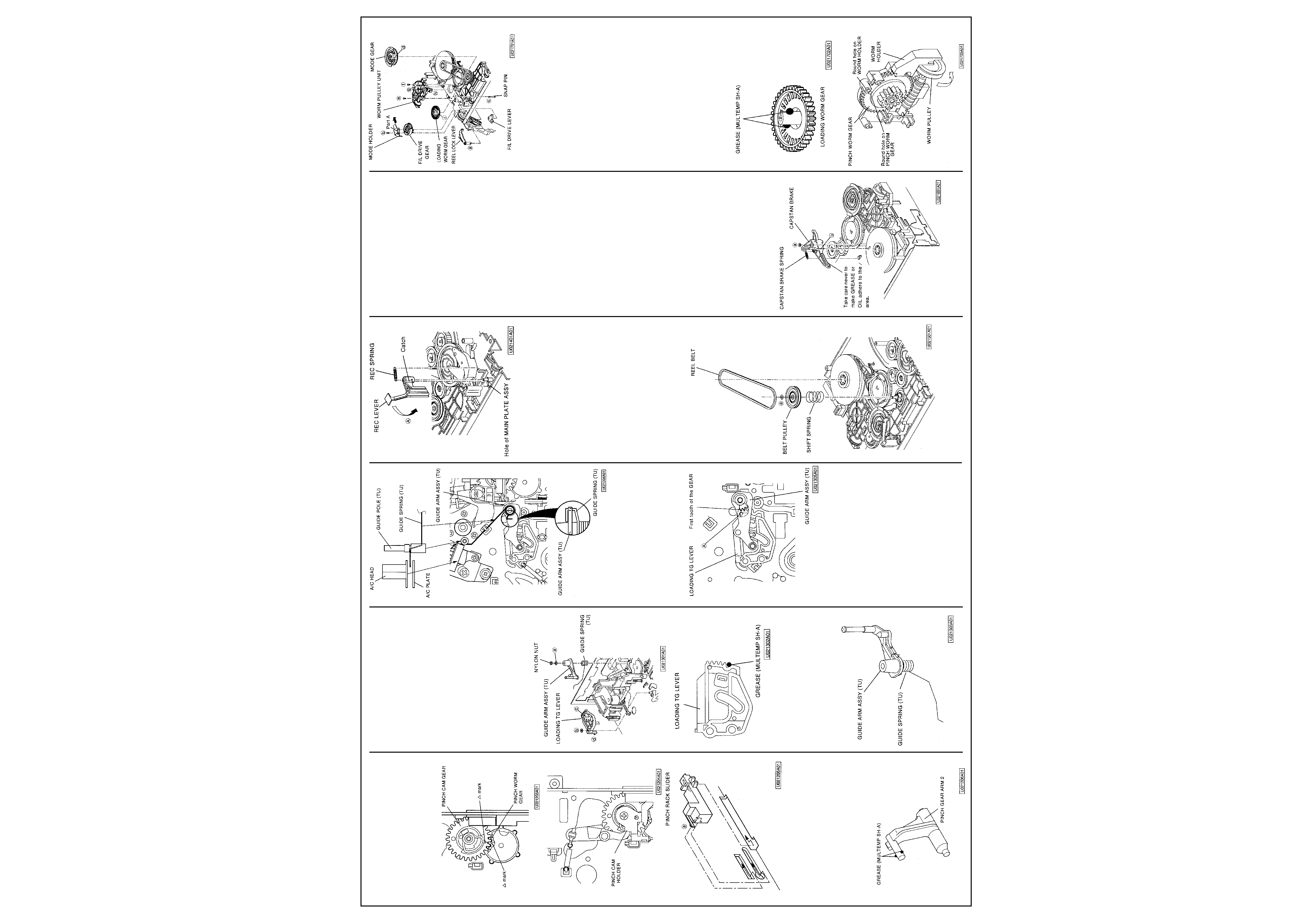
4
MITSUBISHI HS 641 V
RACK SLIDER enters the hole of the MAIN
PLATE ASSY as shown in Fig. 2-12-5.
6 Install the PINCH CAM LEVER shown in Fig.
2-12-1.
7 Install the PINCH CAM SPRING shown in Fig.
2-12-1.
Fig. 2-12-3
Fig. 2-12-4
Fig. 2-12-5
8 Apply GREASE (MULTEMP SH-A)
[859D055O80] to the area specified in Fig. 2-
12-6 on the new PINCH GEAR ARM 2.
9 Install the PINCH GEAR ARM 2 shown in Fig.
2-12-1.
10 Move the PINCH ARM UNIT in the opposite
direction of arrow (A) to install it as shown in
Fig. 2-12-1.
11Install the PINCH ARM CAP shown in Fig. 2-
12-1.
Fig. 2-12-6
2-13 GUIDE ARM ASSY (TU), GUIDE SPRING
(TU), LOADING TG LEVER
Position the set normally.
(Removal)
1 Remove the NYLON NUT shown in Fig. 2-13-
1 to remove the SL WASHER (a) the GUIDE
ARM ASSY (TU) and GUIDE SPRING (TU).
2 Remove the CUT WASHER (b) fastening the
LOADING TG LEVER shown in Fig. 2-13-1.
3 Unfasten the two catches (c) and (d) of the
LOADING TG LEVER shown in Fig. 2-13-1 to
remove the LOADING TG LEVER.
(Installation)
1 Apply GREASE (MULTEMP SH-A
[859D055080] to the area specified in Fig. 2-
13-2 on the new LOADING TG LEVER.
2 Install the LOADING TG LEVER shown in Fig.
2-13-1.
3 Install the CUT WASHER shown in Fig. 2-13-1
to fasten the LOADING TG LEVER.
Fig. 2-13-1
Fig. 2-13-2
4 Fix the GUIDE SPRING (TU) to the GUIDE
ARM ASSY (TU) as shown in Fig. 2-13-3.
5 Fix the GUIDE ARM ASSY (TU) with the
GUIDE SPRING (TU) attached shown in Fig.
2-13-1 to the shaft of the MAIN PLATE ASSY.
6 Install the GUIDE SPRING (TU) on the
position shown in Fig. 2-13-4.
Fig. 2-13-3
Fig. 2-13-4
7 Install the GUIDE ARM ASSY (TU) so that the
first tooth of the gear of the GUIDE ARM
ASSY (TU) shown in Fig. 2-13-5 matches with
hole (A) of the LOADING TG LEVER.
8 Install the SL WASHER and NYLON NUT
shown in Fig. 2-13-1.
9 Perform "Adjustment of GUIDE ARM ASSY
(TU) Height" in Para. 3-5 of "Interchangeabil-
ity Adjustment of the Mechanism".
Fig. 2-13-5
2-14 REC SPRING, REC LEVER
Place the set upside down.
(Removal)
1 Remove the REC SPRING shown in Fig. 2-14-
1.
2 Move the REC LEVER in the direction shown
by arrow (A) until it strikes on the MAIN
PLATE ASSY to remove it as shown in Fig. 2-
14-1.
(Installation)
1 Insert the catch of the REC LEVER shown in
Fig. 2-14-1 into the hole of the MAIN PLATE
ASSY and install the REC LEVER.
2 Install the REC SPRING shown in Fig. 2-14-1.
Fig. 2-14-1
2-15 REEL BELT, BELT PULLEY, SHIFT
SPRING
Place the set upside down.
(Removal)
1 Remove the REEL BELT shown in Fig. 2-15-1.
2 Remove the CUT WASHER (a) fastening the
BELT PULLEY shown in Fig. 2-15-1 to
remove the BELT PULLEY.
3 Remove the SHIFT SPRING shown in Fig. 2-
15-1.
(Installation)
1 Install the SHIFT SPRING shown in Fig. 2-15-1.
2 Fasten the BELT PULLEY shown in Fig. 2-15-1.
3 Install the CUT WASHER shown in Fig. 2-15-
1 to fasten the BELT PULLEY.
4 Install the REEL BELT shown in Fig. 2-15-1.
Note: Take care never to make GREASE or
OIL adhere to the REEL BELT during
installation.
Fig. 2-15-1
2-16 CAPSTAN BRAKE SPRING, CAPSTAN
BRAKE
Place the set upside down. Before performing
replacement in this paragraph, remove the tot
lowing part. Refer to the applicable paragraph
for installation of the part.
· REEL BELT (Para. 2-15)
(Removal)
1 Remove the CAPSTAN BRAKE SPRING
shown in Fig. 2-16-1.
2 Remove the CUT WASHER (a) fastening the
CAPSTAN BRAKE shown in Fig. 2-16-1.
3 Unfasten the catch (b) on the surface of the
CAPSTAN BRAKE shown in Fig. 2-16-1 with
tweezers, etc. to remove the CAPSTAN
BRAKE.
(Installation)
1 Install the CAPSTAN BRAKE shown in Fig. 2-
16-1.
Note: Take care never to make GREASE or
OIL adhere to the area specified in Fig. 2-16-1
during installation of the CAPSTAN BRAKE.
2 Install the CUT WASHER (a) shown in Fig. 2-
16-1 to fasten the CAPSTAN BRAKE.
3 Install the CAPSTAN BRAKE SPRING shown
in Fig. 2-16-1.
2-17 MODE HOLDER, REEL LOCK LEVER,
MODE GEAR, F/L DRiVE GEAR, F/L DRIVE
LEVER, WORM PULLEY UNIT, LOADING
WORM GEAR
Place the set upside down.
(Removal)
1 Unfasten the catch (a) on the surface of the
REEL LOCK LEVER shown in Fig. 2-17-1
with tweezers, etc. to remove the REEL LOCK
LEVER.
2 Unscrew the MODE HOLDER fastening
screw (b) shown in Fig. 2-17-1 to remove the
MODE HOLDER.
3 Unfasten the catch (c) of the SNAP PIN shown
in Fig. 2-17-1 with the tweezers, etc. to
remove the SNAP PIN.
4 Unfasten the catch (d) on the surface of the
MODE GEAR shown in Fig. 2-17-1 with
tweezers, etc. to remove the MODE GEAR.
5 Remove the F/L DRIVE GEAR shown in Fig.
2-17-1 from the shaft of the MAIN PLATE
ASSY.
6 Remove the F/L DRIVE LEVER shown in Fig.
2-17-1.
Fig. 2-16-1
Fig. 2-17-1
7 Unscrew the two WORM PULLEY UNIT
fastening screws (e) and (f) shown in Fig. 2-
17-1.
8 Remove the LOADING BELT. (Refer to Para.
2-11 for the removal method.)
9 Unfasten the two catches (g) and (h) of the
WORM PULLEY UNIT shown in Fig. 2-17-1 to
remove the WORM PULLEY UNIT.
10 Unfasten the catch (i) on the surface of the
LOADING WORM GEAR shown in Fig. 2-17-
1 to remove the LOADING WORM GEAR.
(Installation)
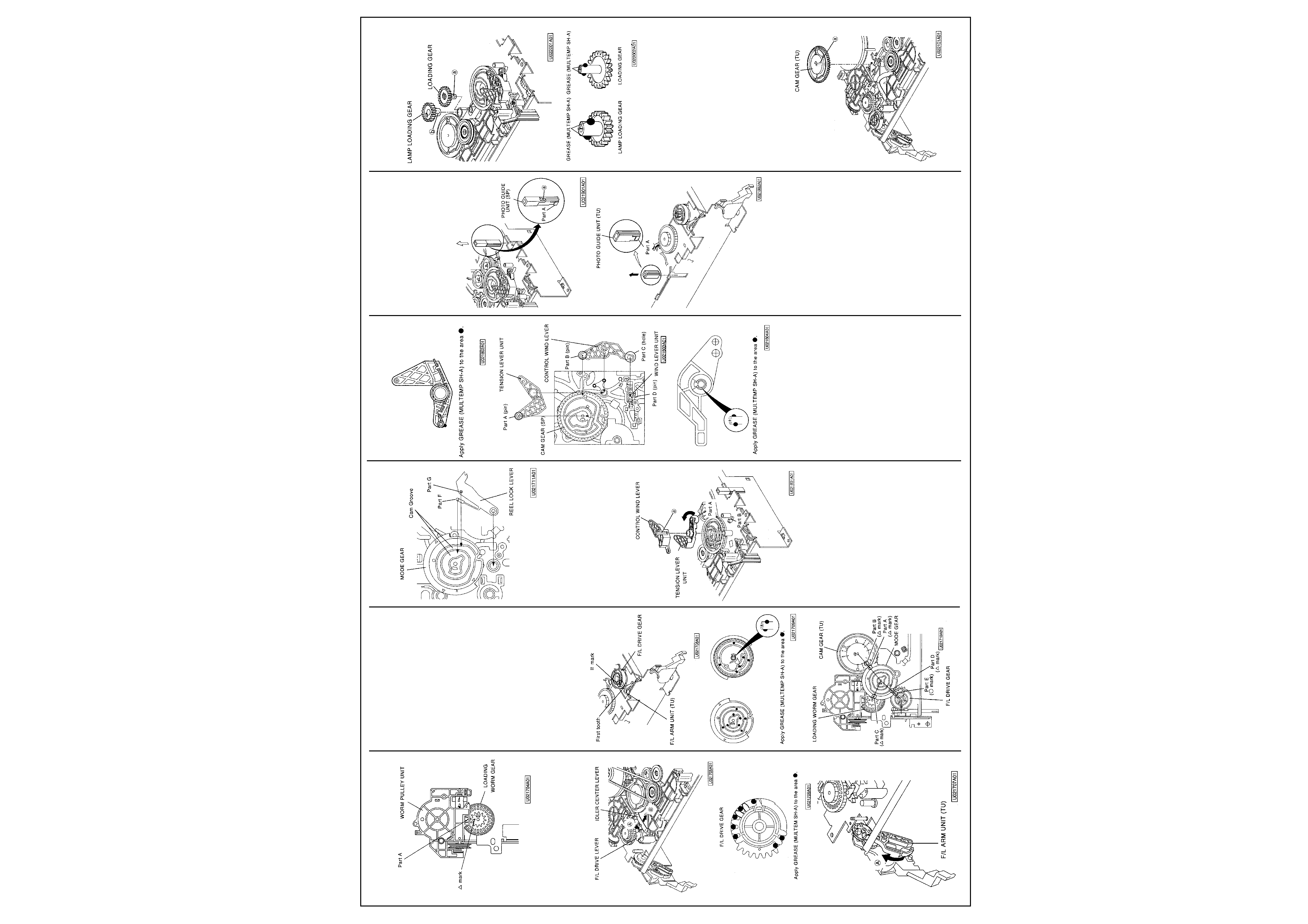
1 Apply GREASE (MULTEMP SH-A)
[859D055O80] to the area specified in Fig. 2-
17-2 on the new LOADING WORM GEAR.
2 Install the LOADING WORM GEAR shown in
Fig. 2-17-1.
3 Turn the WORM PULLEY shown in Fig. 2-17-3
SO that the round hole of the PINCH WORM
GEAR matches with that of the WORM
HOLDER.
4 Install the WORM PULLEY UNIT so that the
mark on the LOADING WORM GEAR shown
in Fig. 2-17-4 matches with the part A of it.
5 Fasten the LOADING BELT. (Refer to Para. 2-
11.)
6 Install the F/L DRIVE LEVER shown in Fig. 2-
17-1.
Fig. 2-17-2
Fig. 2-17-3
Mechanical Adjustments
and Replacements Cont'd
5
MITSUBISHI HS 641 V
Fig. 2-17-4
7 Fully move the F/L DRIVE LEVER shown in
Fig. 2-17-5 in the direction shown by arrow
8 Apply GREASE (MULTEMP SH-A)
[859D055O80] to the area specified in Fig. 2-
17-6 on the new F/L DRIVE GEAR.
9 Move the F/L ARM UNIT (TU) shown in Fig.
2-17-7 in the direction shown by arrow (A).
Fig. 2-17-5
Fig. 2-17-6
Fig. 2-17-7
10 Install the F/L DRIVE GEAR so that the first
tooth of the gear of the F/L ARM UNIT (TU)
matches with the II mark on the F/L DRIVE
GEAR as shown in Fig. 2-17-8.
11Fully move the IDLER CENTER LEVER
shown in Fig. 2-17-5 in the direction shown by
arrow (B).
12 Apply GREASE (MULTEMP SH-A)
[859D055O80] to the area shown in Fig. 2-1
7-9 on the new MODE GEAR.
13 Install the MODE GEAR shown in Fig. 2-17-
10 so that;
· A mark on the part A of the MODE GEAR
matches with A mark on the part B of the CAM
GEAR (TU),
· A mark on the part C of the MODE GEAR
points to the centre of the LOADING WORM
GEAR, and
· A mark on the part D of the MODE GEAR
matches with the 0 mark on the part E of the
F/L DRIVE GEAR.
14 Make sure that the A mark on the PINCH
WORM GEAR shown in Fig. 2-12-3 matches
with the A mark on the PINCH CAM GEAR.
15 Push the SNAP PIN shown in Fig. 2-17-1 into
the centre hole of the MODE GEAR from the
surface to install it.
16 Move the MODE HOLDER shown in Fig. 2-1
7-1 in the direction shown by the arrow so
that the part A of it is fixed to the shaft of the
MAIN PLATE ASSY and install it.
Fig. 2-17-8
Fig. 2-17-9
Fig. 2-17-10
17 Install the REEL LOCK LEVER so that the
pins on the parts F and G of the REEL LOCK
LEVER shown in Fig. 2-17-11 enter the cam
groove of the MODE GEAR.
Fig. 2-17-11
2-18 CONTROL WIND LEVER, TENSION
LEVER UNIT
Place the set upside down.
(Removal)
1 Unfasten the catch (a) on the surface of the
CONTROL WIND LEVER shown in Fig. 2-18-1
with tweezers, etc. to remove the CONTROL
WIND LEVER.
2 Remove the TENSION LEVER UNIT shown
in Fig. 2-18-1.
Fig. 2-18-1
(Installation)
1 Apply GREASE (MULTEMP SH-A)
[859D055O80] to the area specified in Fig. 2-
18-2 on the new TENSION LEVER UNIT.
2 Install the TENSION LEVER UNIT shown in
Fig. 2-18-1 with taking care of the following.
· Make the pin on the part A of the TENSION
LEVER UNIT shown in Fig. 2-18-3 enter the
cam groove on the CAM GEAR (SP).
· Move the part A of the spring of the TENSION
LEVER UNIT shown in Fig. 2-18-1 in the
direction shown by the arrow. Install the
TENSION LEVER UNIT so that the part A of
the spring is hooked to the part B of the
TENSION ARM.
3 Apply GREASE (MULTEMP SH-A)
[859D055O80] to the area specified in Fig. 2-
18-4 on the new CONTROL WIND LEVER.
4 Install the CONTROL WIND LEVER so that
the pin on the part B on the CONTROL WIND
LEVER shown in Fig. 2-18-3 enters the cam
groove of the CAM GEAR (SP) and that the
pin of the part D of the WIND LEVER UNIT
enters the hole of the part C on the CON-
TROL WIND LEVER.
Fig. 2-18-2
Fig. 2-18-3
Fig. 2-18-4
2-19 PHOTO GUIDE UNIT (SP), PHOTO
GUIDE UNIT (TU)
Place the set upside down.
Before performing replacement in this para-
graph, remove the following parts. Refer to the
applicable paragraph for installation of each
part.
· LOADING BELT (Para. 2-11)
· MODE HOLDER (Para. 2-17)
· REEL LOCK LEVER (Para. 2-17)
· MODE GEAR (Para. 2-17)
· WORM PULLEY UNIT (Para. 2-17)
(Removal)
1 Unfasten the catch (a) of the PHOTO GUIDE
UNIT (SP) shown in Fig. 2-19-1 with tweez-
ers, etc. and remove the PHOTO GUIDE
UNIT (SP) in the direction shown by the
arrow.
2 Remove the PHOTO GUIDE UNIT (TU)
shown in Fig. 2-19-2 in the direction shown by
the arrow.
(Installation)
1 Push the PHOTO GUIDE UNIT (TU) into the
DECK to the bottom, with the part A shown in
Fig. 2-19-2 toward the inside of DECK.
Note: Never touch the transparent part of the
PHOTO GUIDE UNIT (TU).
2 Push the PHOTO GUIDE UNIT (SP) into the
DECK so that the catch (a) is hooked, with
the part A shown in Fig. 2-19-1 toward the
inside of DECK.
Note: Never touch the transparent part of the
PHOTO GUIDE UNIT (SP).
Fig. 2-19-1
Fig. 2-19-2
2-20 LOADING GEAR, LAMP LOADING GEAR
Place the set upside down.
Before performing replacement in this para-
graph, remove the following parts. Refer to the
applicable paragraph for installation of each
part.
· LAMP GUIDE (Para. 2-7)
· REEL BELT (Para. 2-15)
(Removal)
1 Unfasten the catch (a) on the surface of the
LOADING GEAR shown in Fig. 2-20-1 with
tweezers, etc. to remove the LOADING
GEAR.
2 Unfasten the catch (b) on the surface of the
LAMP LOADING GEAR shown in Fig. 2-20-1
with tweezers, etc. to remove the LAMP
LOADING GEAR.
(Installation)
1 Apply GREASE (MULTEMP SH-A)
[859D055O80] to the area specified in Fig. 2-
20-2 on the new LAMP LOADING GEAR.
2 Install the LAMP LOADING GEAR shown in
Fig. 2-20-1.
3 Apply GREASE (MULTEMP SH-A)
[859D055O80] to the area specified in Fig. 2-
20-2 on the new LOADING GEAR.
4 Install the LOADING GEAR shown in Fig. 2-
20-1.
Fig. 2-20-1
Fig. 2-20-2
2-21 CAM GEAR (TU)
Place the set upside down.
Before performing replacement in this para-
graph, remove the following parts. Refer to the
applicable paragraph for installation of each
part.
· LOADING BELT (Para. 2-11)
· REEL BELT (Para. 2-15)
· CAPSTAN BRAKE SPRING (Para. 2-16)
· CAPSTAN BRAKE (Para. 2-16)
· MODE HOLDER (Para. 2-17)
· REEL LOCK LEVER (Para. 2-17)
· MODE GEAR (Para. 2-17)
(Removal)
1 Unfasten the catch (a) on the surface of the
CAM GEAR (TU) shown in Fig. 2-21-1 with
tweezers, etc. to remove the CAM GEAR
(TU).
Fig. 2-21-1
Mechanical Adjustments
and Replacements Cont'd