
R
V
A : Création P. LE SIGNOR
05/99
Rédigé par
Verifié par
Approuvé par
E
R
B : Modif MTS 2.0 english
06/99
Written by
Checked by
Approuved by
V
S
C : Ajout ASTRAL et GEO
07/99
X. GLASSON
B. LEGORGEU
G. LEBASTARD
I
I
D : Modif Testmode
software
02/00
S
O
E : Ajout GEO WAP
04/00
I
N
O
S
N
S
Mitsubishi Electric Telecom Europe SA
Version E
ZA le Piquet, 35370 Etrelles
Date: 04/00
Phone: +33 2 99 75 71 00
Fax: +33 2 99 75 71 47
LEVEL 3 SERVICE
FA9M030110
GALAXY
ASTRAL
GEO
GEO WAP
(DUAL BAND)

Mitsubishi Electric Telecom Europe SA
Version E
ZA le Piquet, 35370 Etrelles
Date: 04/00
Phone: +33 2 99 75 71 00
Fax: +33 2 99 75 71 47
1/29
TABLE OF CONTENTS
1 Block Diagram
3
1.1
Schematic
3
1.2
Description of Block Diagram.
3
1.2.1
IC300
One-C (VWS22100).
3
1.2.2
IC100
IPD (Rohm BH6070KU).
3
1.2.3
IC600
RF-IC (Hitachi HD155121FEB).
3
1.2.4
Memory system.
4
1.2.5
System Clock.
4
2. Battery management.
5
2.1
Block Diagram.
5
2.2
Description.
5
2.3 Charging process.
7
2.4
Main characteristics.
8
2.5
Autonomy Control.
8
2.6
Power on.
9
2.7
Power off.
10
2.8
Real Time Clock (Geo and Geo WAP)
10
3. RF Section.
11
3.1
Frequency range.
11
3.1.1
E-GSM Frequency :
11
3.1.2
DCS Frequency :
11
3.2
Synthetiser Circuit Description.
12
3.3
RF Block Diagram.
13
3.4
Reception
14
3.4.1
Reception Block Diagram.
14
3.4.2
Description of Reception Block Diagram
14
3.5
Transmission.
15
3.5.1
Transmission Block Diagram.
15
3.5.2
Description of Transmission Block Diagram.
15
3.5.3
Power Control.
16
4. Speech coder.
17
4.1
Full rate / Half rate / Enhanced full rate.
17
5.
Analogue Audio.
19
Level 3 Service Manual
GALAXY ASTRAL GEO GEO WAP
Version E
Mitsubishi Electric Telecom Europe SA
Date: 04/00
ZA le Piquet 35370 Etrelles
Phone: +33 2 99 75 71 00
2/29
Fax: + 33 2 99 75 71 47
5.1
Buzzer.
19
5.2
Speaker (RX audio).
19
5.3
Micro (TX audio).
19
6. Testmode Software.
20
6.1
Equipment installation
20
6.2
Software (MTS) installation
21
6.2.1
Simple Setup :
21
6.2.2
Complete Setup :
21
6.3
Software (MTS) description
22
6.3.1
MMI Testmode interface : description of functions
22
7. Basic Adjustment.
27
7.1
Power Adjustment.
27
7.2
RSSI control.
28
8. Software Version .
28
9. Trouble Shooting help guide
29
Level 3 Service Manual
GALAXY ASTRAL GEO GEO WAP
Mitsubishi Electric Telecom Europe SA
Version E
ZA le Piquet, 35370 Etrelles
Date: 04/00
Phone: +33 2 99 75 71 00
Fax: + 33 2 99 75 71 47
3/29
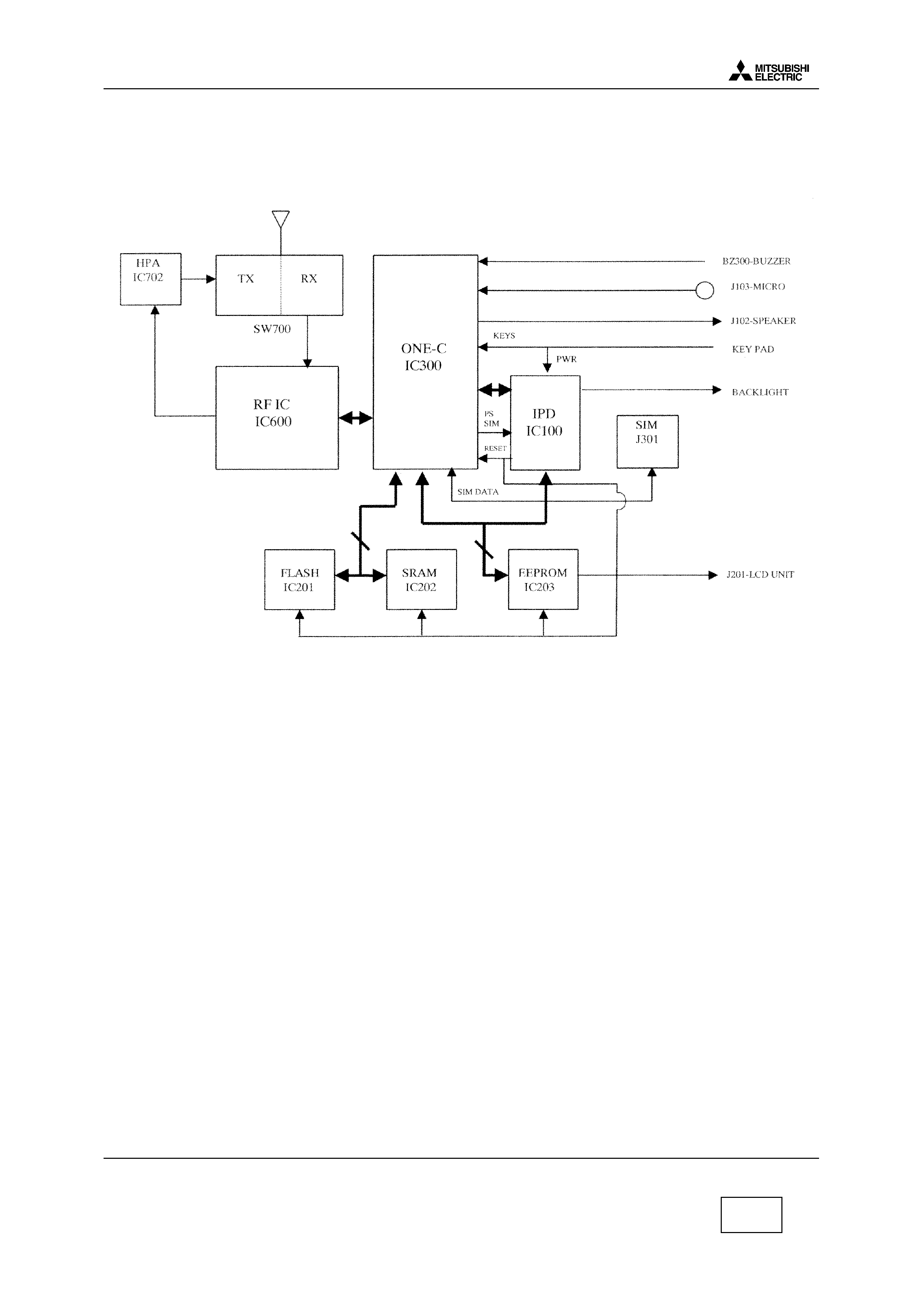
1
Block Diagram
1.1
Schematic
1.2
Description of Block Diagram.
1.2.1
IC300
One-C (VWS22100).
IC300 includes in one same chipset Base Band part, DSP, CPU, A/D, D/A converters, TDMA
framecounters, a TX GMSK modulator, a TX power ramping circuit, RX filters. IC300 carries out the
management of the battery charging, and of the audio part. It interfaces with the radio frequency
part.
1.2.2
IC100
IPD (Rohm BH6070KU).
IC100 provides the different powers supplies to RFBB board : 2.8RTC, PSTCXO, 2.8VANA, PSSYN,
2.8VAUD, VBAT, 3.6VB, 2.8VD, 5VSIM. The management of the battery charging is carried out by
internal circuit of IC100.
1.2.3
IC600
RF-IC (Hitachi HD155121FEB).
Transceiver IC for E-GSM and DCS Dual Band cellular systems.
Serial bus
Parallele bus
Level 3 Service Manual
GALAXY ASTRAL GEO GEO WAP
Version E
Mitsubishi Electric Telecom Europe SA
Date: 04/00
ZA le Piquet 35370 Etrelles
Phone: +33 2 99 75 71 00
4/29
Fax: + 33 2 99 75 71 47
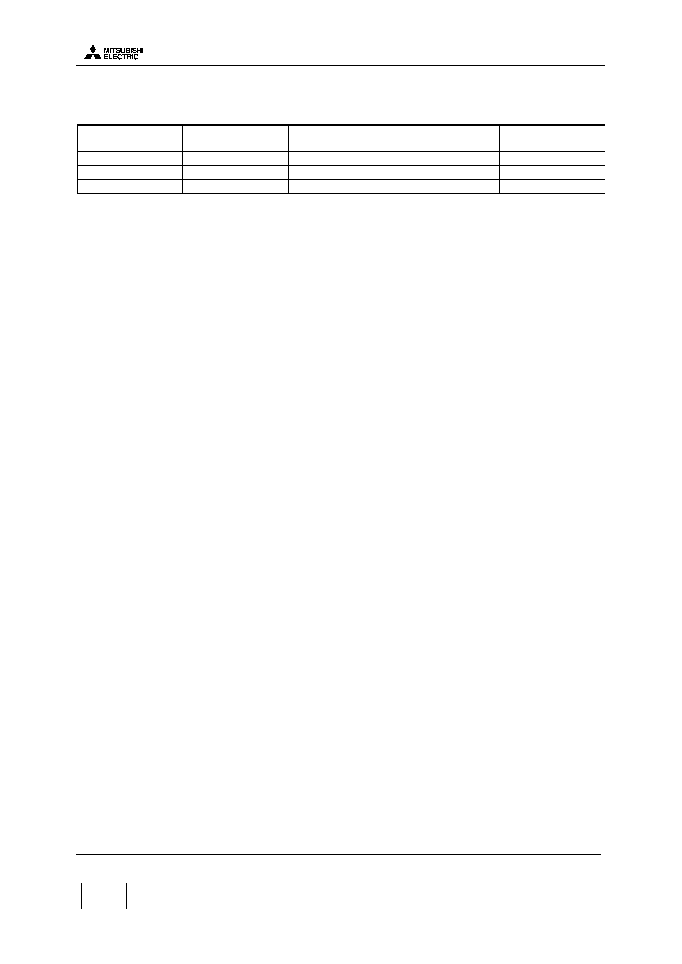
1.2.4
Memory system.
Location
Type
Data
Size
Galaxy Astral Geo
Size
Geo WAP
IC201
Flash ROM
CPUprogram code 1 MB
2MB
IC202
RAM
Data for CPU work 128 kB
128 kB
IC203
EEPROM
Data user, RF adj.
64 kB
128 kB
1.2.5
System Clock.
The system clock for the telephone is 13 MHz TCXO, generated by X600. It is processed in IC300 to
provide serial clock for LCD, EEPROM, and IC100. The clock is buffered in IC300 One-C, and then
fed to IC100 IPD as " CPU CLK " . It is available on pin 56 of IC100.
During Stand-By mode, the system clock is not managed from X600 TCXO but from X300 ( " slow
clock " at 32.768 kHz).