MITSUBISHI DIGITAL ELECTRONICS AMERICA, INC.
9351 Jeronimo Rd. Irvine, CA 92618
Copyright © 2002 Mitsubishi Digital Electronics America, Inc.
All Rights Reserved
Operating conditions:
Temperature: 5°C to 35°C
Operation status:
Horizontal
Video output:
1.0 V (p-p), 75
, negative
sync., pin jack x 1
S Video output:
(Y) 1.0 V (p-p), 75
, nega-
tive sync., Mini DIN 4-pin x 1
(C) 0.286 V (p-p), 75
Component Video output: (Y) 1.0 V (p-p), 75
,
negative sync., pin jack x 1
(Cr, Pr)/(Cb, Pb) 0.7 V (p-p),
75
, pin jack x 2
Digital Audio output:
(Bitstream/PCM) 0.5 V (p-p),
75
, pin jack x 1,
Optical connector x 1
Analog Audio output:
2.0 V (rms), 680
, pin jack
2 CH L R x 2,
5.1 CH SURROUND x 6
CAUTION
Before servicing this chassis, it is important that the service person reads all SAFETY PRECAUTIONS and the
SAFETY NOTICE in this manual.
SPECIFICATIONS
Power Supply:
120V AC, 60 Hz
Power Consumption:
17W
Weight:
5.6 lb.
External Dimensions:
17"x 2-3/4"x8-7/8"
(W/H/D)
Signal System:
Standard NTSC
Laser:
Semiconductor laser,
wavelength 650nm/780nm
Frequency Range:
(Digital Audio)
DVD Linear -
48 kHZ Sampling: 4 Hz to 22 kHz
96 kHZ Sampling: 4 Hz to 44 kHz
Signal-To-Noise Ratio:
More than 112 dB (EIAJ)
Audio Dynamic Range: More than 108 dB (EIAJ)
Harmonic Distortion:
Less than 0.002%
Wow and flutter:
Below measurable level
(less than ± 0.001%
(W.PEAK)) (EIAJ)
Service
Manual
2002
MITSUBISHELECTRIC
Model
DD-8030
DVD Player
SECTION 1
GENERAL DESCRIPTIONS
SECTION
1
GENERAL
DESCRIPTIONS
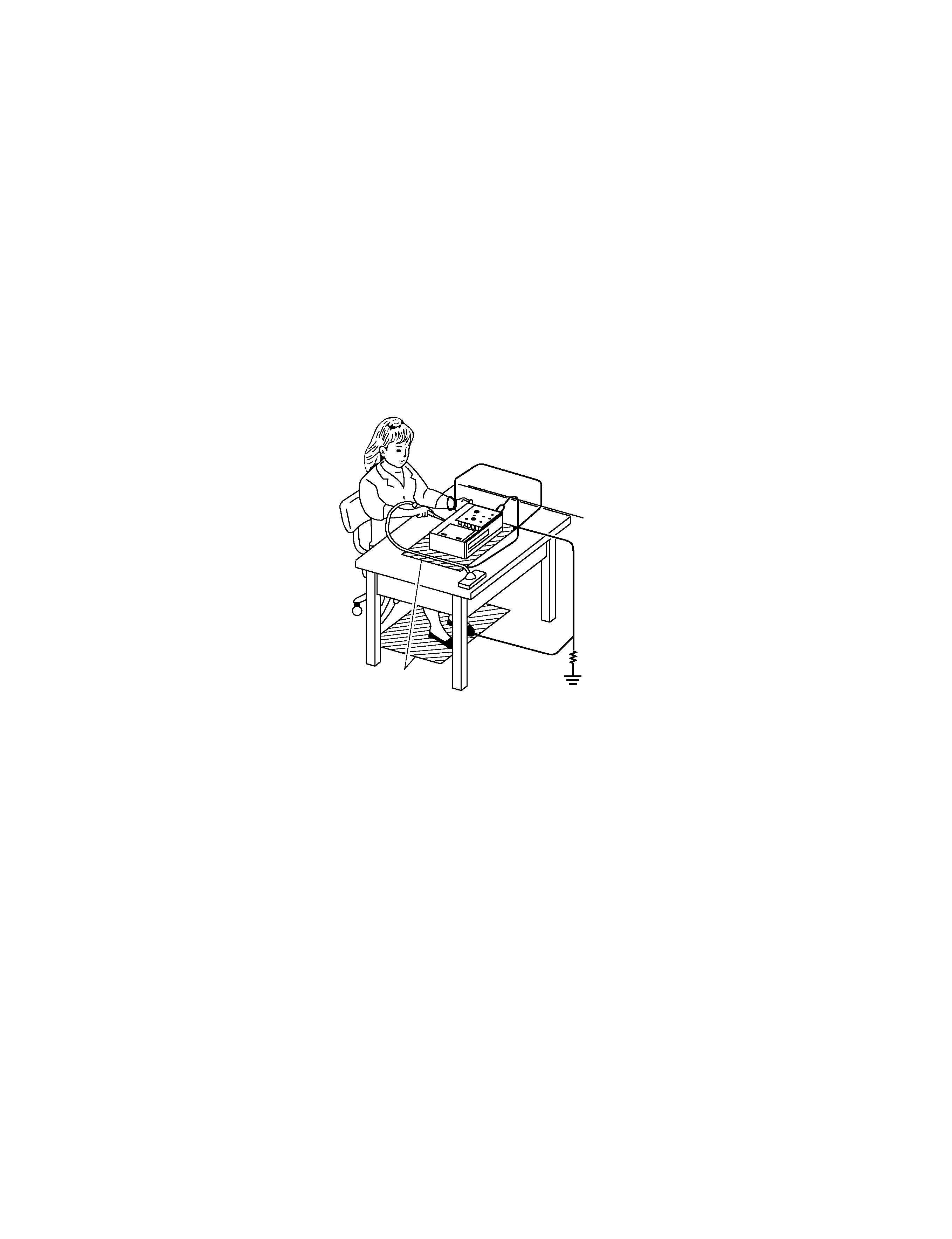
1M
Ground conductive
wrist strap for body.
Soldering iron
with ground wire
or ceramic type
Conductive mat
The ground resistance
between the ground line
and the ground is less than 10
.
The Pickup Head consists of a laser diode that is very susceptible to external static electricity.
Although it may operate properly after replacement, if subjected to electrostatic discharge during replacement,
its life might be shortened. When replacing the laser diode, LSI's and IC's, use a conductive mat, soldering iron
with ground wire, etc. to protect against damage from static electricity.
1. PREPARATION FOR SERVICING
GENERAL
DESCRIPTIONS
1-1
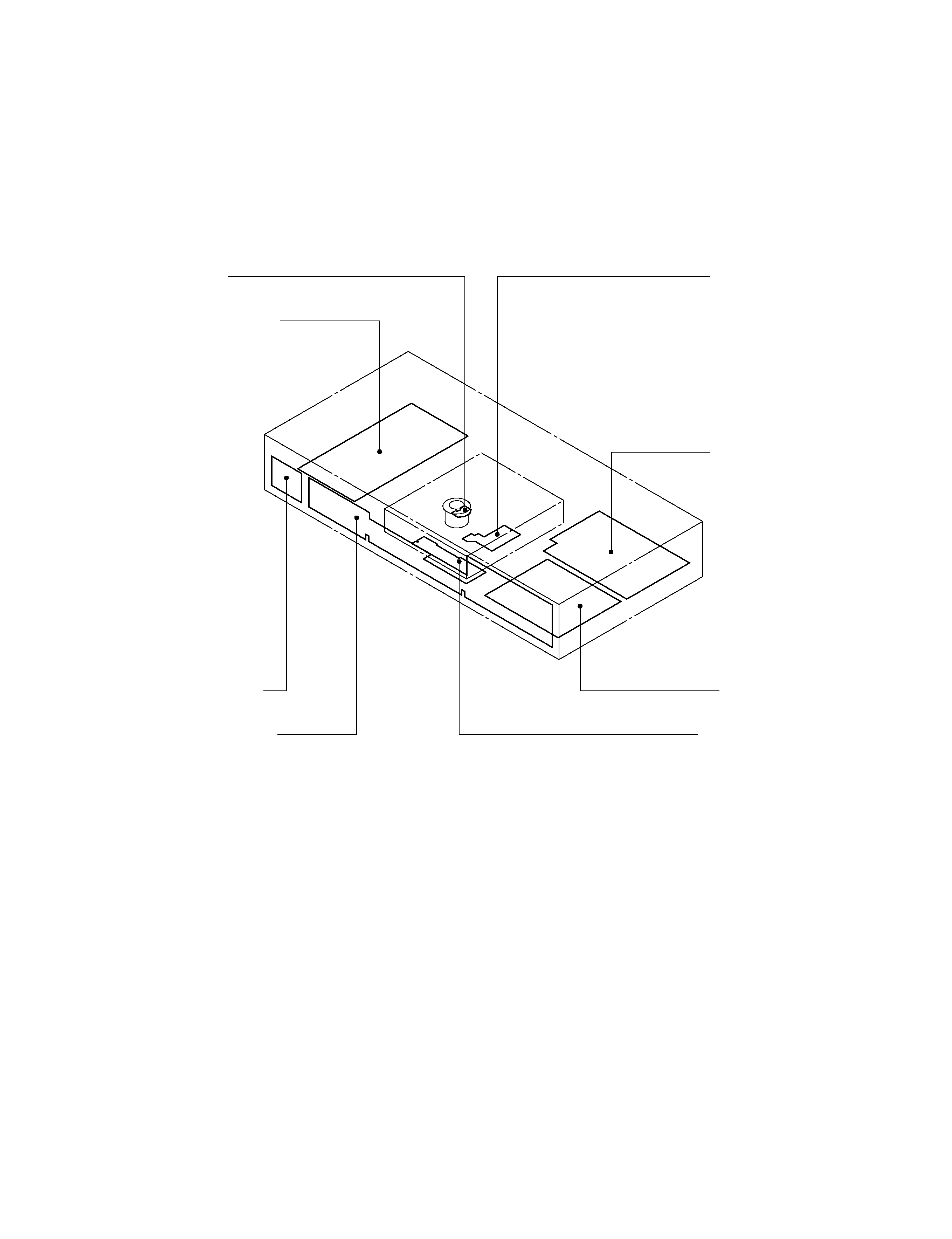
2. LOCATION OF MAIN PARTS AND MECHANISM PARTS
2-1. Location of Main Parts
Fig. 1-2-1
EU01 Main PC board
EU05 Output PC board
EU02 Power supply PC board
EU04 Power SW PC board
Loading motor PC board
Disc motor PC board
Feed motor PC board
EU03 Front display PC board
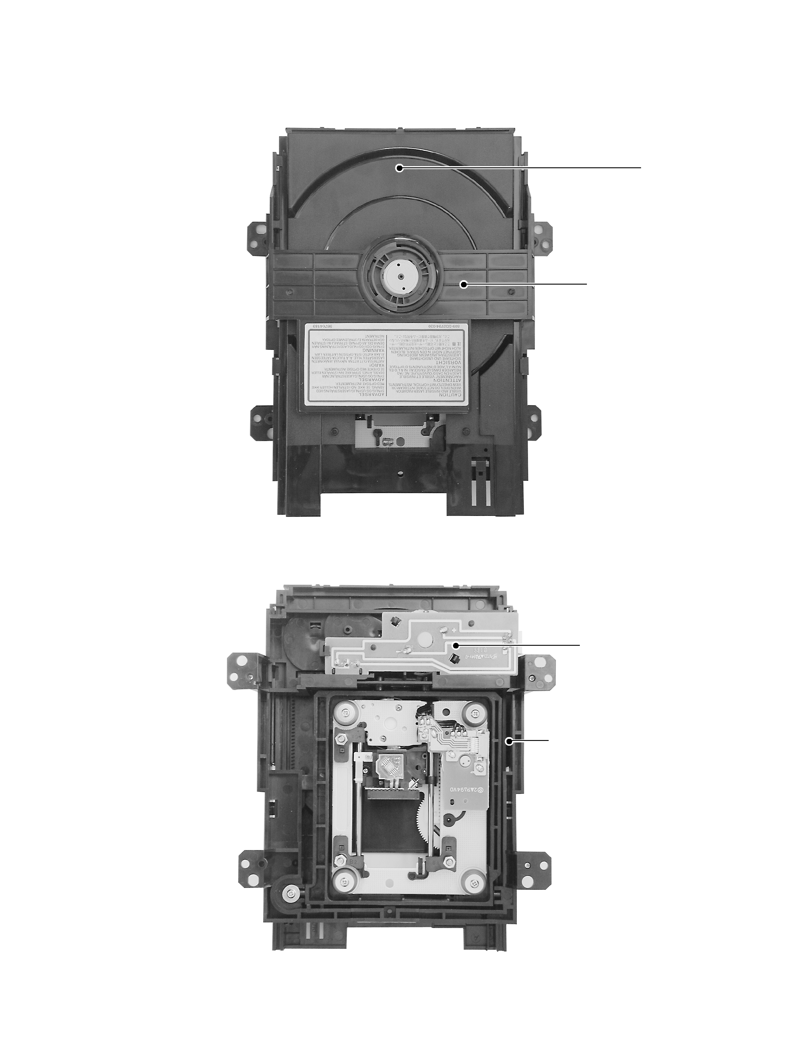
2-2. Location of Mechanism Parts
2-2-1. Type A
Fig. 1-2-2 Mechanism chassis assembly (Top side)
Fig. 1-2-3 Mechanism chassis assembly (Bottom side)
Tray
Clamper stay
Loading motor
PC board
Mechanism chassis
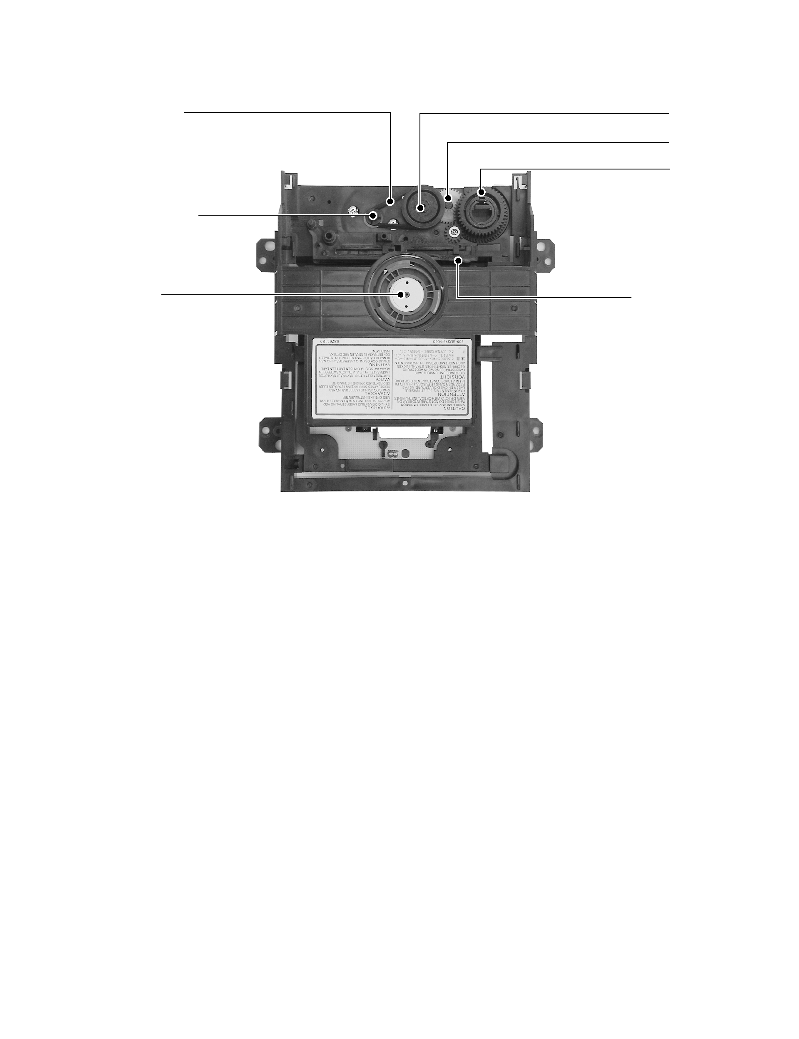
Fig. 1-2-4 Mechanism chassis assembly (Internal side)
Loading belt
Loading motor
Cam Slider
Gear
Gear
Gear
Clamper