
Service Manual
Published by MD 0312 RCS Service
Subject to modification
3104 205 5002.3
UNIVERSAL HOME THEATER Remote control
RC3200/A
RC3200/U1S
RC3200/M1S
TABLE OF CONTENTS
Chapter
Specification / Service hints ......................................................
1
Dismantling hints .....................................................................
2
Circuit description .....................................................................
3
Troubleshooting .......................................................................
4
Electrical diagram ....................................................................
5
Assembly diagram .....................................................................
6
Exploded view ...........................................................................
7
Partslist
...................................................................................
8
© Royal Philips Electronics NV
All rights are reserved. Reproduction in whole or in part is prohibited
without the prior written consent of the copyright owner.
marantz

SPECIFICATIONS
1-1
Display
Monochrome touch screen LCD with 4 gray levels and
digital contrast control.
Resolution: 160 x 100 pixels
Blue EL backlighting for LCD and hard buttons
Interface
3-wire (RS232) serial port connector
Software
Built-in Marantz RC codes
Total number of devices limited only by memory
Infrared (IR)
Infrared sending LED and learning eye
Operating distance of 33 feet (10 meters)
Learning frequency up to 56 kHz and 455 kHz
Learning distance 1 inch (2 cm) up to 4 inch (10 cm)
2-way communication with specific marantz equipment
Memory
1 MB non-volatile flash memory
Batteries
3 AA-batteries (3 x 1,5V): primary or rechargeable
Power management
Power on by tapping the LCD touch screen or by pressing
the Backlight button
Power off automatically
Dimensions
7.8 inch x 3 inch x 1.3 inch (177mm x 74mm x 33mm)
Operating temperature 41°F to 113°F (5°C to 45°C)
Accessories
only for RC3200/U1S/M1S
only RS3200/A
RS232 cable for PC connection
None
IFU RC3200
3 AA-batteries
SERVICE HINTS
-RC3200 information
Press and hold the Mode button for 3 seconds -Tap SETUP - go to page3/3 with page up or page down button.
This page contains following information:
Free memory :
Boot version :
System version :
Application version :
Configuration file :
-Cleaning RC3200
Use a soft, damp cloth to clean the RC3200
If the LCD touch screen is dirty, clean it with a soft cloth moistened with a diluted window-cleaning solution.
After a repair please make the LCD touch screen always clean !
-Update the RC3200
Please check after each repair the RC300 application version.
Check the version on the website. Is the version higher on the website, please download the new version from
the Firmware.
You can find this on the Marantz website http://www.marantz.com
2-1
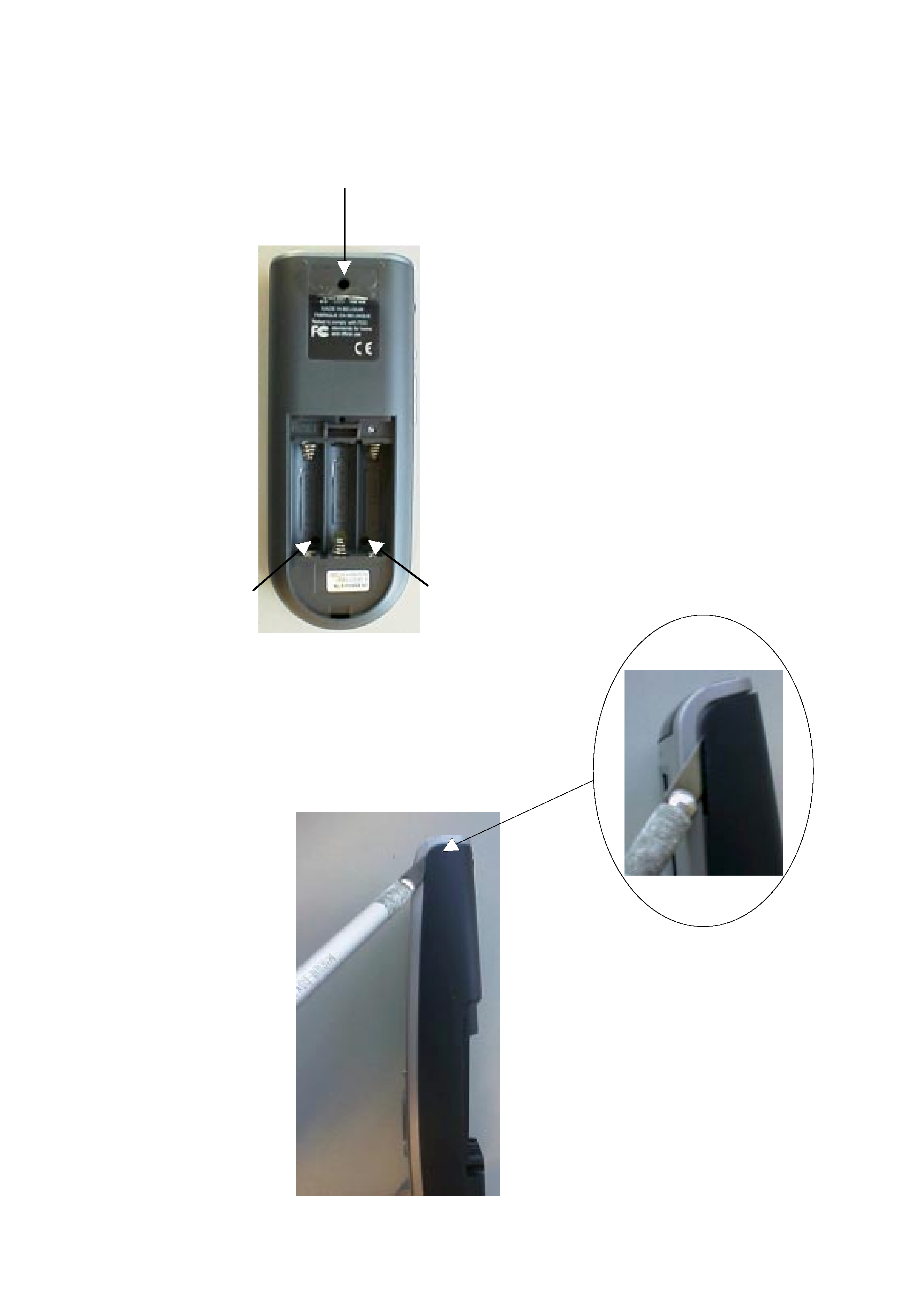
DISMANTLING HINTS
1. Remove battery lid
2. Remove label a little. see picture1
3. Remove 3 x screw as shown in picture 1
picture 1
4. Put a sharp knife between toppart and bottompart
and use this as lever to separate the two parts. see picture 2
picture 2
2 x 8mm
2 x 8mm
2 x 8mm

3-1
CIRCUIT DESCRIPTION
1
Power supply
Components: 7201
The power supply makes use of the LT1761 low drop linear regulator of Linear Technologies. The output voltage is 3.3V.
2
Reset & delayed reset.
Components:
-reset: 7202
-delayed reset: around 7203, 7204
The S-809 (Panasonic) detects the hardware reset level of the batteries. Below this level (2.8V) reset is passed to the
"delayed reset" circuit.
The "delayed reset circuit" is activated by the S-809 or the reset switch 1203. It will delay the reset signal by approx. 80ms and
has a hysteresis of 200mV
3
Battery level measurement
Components: around 7206, 7207
The battery voltage is measured via a 1:2 divider by the master microcontroller. This divider is switched on/off by the master
by means of 7206 and 7207.
4
EL-foil driver
Components: around 7205
The EL-sheet is driven by the D371 (Durel). This component generates a high-voltage semi sinewave by switching a coil of
2.2mH. It contains 2 oscillators: a high-frequency oscillator switching into the inductor at approx. 17kHz. A low-frequency
oscilator drives the EL-sheet at approx. 500Hz. The EL-sheet is driven with approx. 75Vpeak.
Zener diodes 6208 and 6209 limit the sinewave voltage when no sheet is attached (during repair of the unit).
5
+/- 17V generator
Components: around 7210
The + and - 17V are generated by the MC64063A, a DC-to-DC converter who is used in a step-up configuration.
The switching frequency ranges up to 150kHz (depending on the load) with ringing on the edges of approx. 3MHz.
The generator is switched on/off via 7208 and 7209 from the master microcontroller.
6
Master microcontroller & memories
Components: 7101, 7115, 7103, 7102
The master is the main microcontroller in the system (M30800, Mitsubishi). It uses external flash program memory
(AM29LV800BT, AMD) and SRAM (CY62256V, Cypress). Address selection is performed with 74LV139.
The master runs from two crystals: 7.3728MHz, onlu runing when active. The other crystal of 32.768kHz is always running,
even in sleep mode.
7
Buzzer
Components: around 1103
The sound function is made by a piezo-electric buzzer. The steering frequency range is 200Hz ~ 8kHz.
8
RS232 transmitter
Components: around 7105, 7106
This circuit converts the RS232 outgoing signal from the master between 0 and 3.3V to -15 and +15V levels.
RS232 communication is set at 115kBaud both directions.
9
RS232 receiver & detection.
Components: around 7107, 7108, 7109
Transistor 7107 converts the incoming RS232 signals between -/+15V into 0-3V levels towards the master.
Transistors 7108 and 7109 perform a RS232 incoming signal detection and interrupt the master during sleep mode when
communication starts from a connected PC.
10 Touchscreen.
Components: around 7111, 7112, 7113, 7114
A resistive touchscreen is used, composed of two layers of resistive material. Pressing the screen causes a short-circuit
between the two layers.
The touchscreen is operated in two steps:
1. detection of a touch
2. reading of the actual position of the touch
Detection is done by connecting one layer to ground and the second layer to 3.3V with a pull-up resistor. The voltage on the
second layer will change from 3.3V to 0V when touching.
Readout is performed in 2 phases, each determining one coordinate.
First, layer 1 is connected between 3V3 and ground. The potentiometric position of the touch location can be read by
measuring the voltage on the layer 2.
The other coordinate is read by interchanging the layers in previous procedure.

CIRCUIT DESCRIPTION
3-2
11
LCD
Components: 1101
The LCD module (Wintek) is a STN type 100x160 pixel including the driver HD66421 of Hitachi. The touchscreen is glued on
top the the LCD module.
The LCD module uses a 8 bit bus directly iterfacing to the databus of the master.
It uses two voltages: 3.3V for the logic and 17V for the LCD glass drive.
The LCD driver uses a clock of approx. 190kHz to generate all timing.
12 Keyboard
Components: 0102, etc...
The keyboard is a matrix of 6 x 3 keys. It is static when no key is pressed, and scanned when a key is applied.
13 Slave microcontroller
Components: 7301
The slave microcontroller M37540M4 (Mitsubishi) takes most of the real-time functions: IR-sending, IR learning and steering
the database microcontroller.
Sending IR is performed via pins 28 and 29, combining envelope and carrier with AND-gate 7302.
Transistors 7303 and 7304 combine the IR-sending signals from slave uC and database uC towards the IR-transmitter circuit.
The salve uC also switches on/off the power of the learing circuit via 7305.
Bidirectional communication to the master uC goes via a UART at 57kBaud.
Communication to the database uC goes via a 3-line dedicated bus.
14
Infrared transmitter
Components: around 7307, 7308
The IR-transmitter transmits any IR-code coming from slave or database uC.
It steers two IR-transmission diodes with a peak current of approx. 300mA in each of them.
The IR-diodes transmit invisible infrared light at 940 nm in an angle of 2 x 25 degr.
An electrolytic capacitor of 100uF smoothen-out the carrier frequency in order to have only the average current flowing from
the batteries (envelope of the IR-code).
There are many many brands with each several IR-codes. Basically, all codes consist of a low bitrate burst (around 1kbit or
slower) modulated on a carrier of 30 - 60kHz, and repeated at a rate of 5 - 20Hz.
15 Learning circuit
Components: around 7309, 7310
This circuit is used for learning IR-codes. It uses signals captured by the IR-transmission LEDs 6301and 6302. Transistor
7309 amplifies the signal. Opamp LM393-B puts a minimum threshold and amplifies further. The output of LM393-B contains
the carrir frequency and is fed to the slave IC for carrier frequency measurement. The output is also fed onto a detector. This
has a time constant suitable to detect to the envelope signal of the IR-code. Opamp LM393-A cleans up and its output is fed
also into the slave uC for envelope recording.
16 IR - Receiver
Infrared receptor 6306 and surrounding components
17 Not impemented functions (in circuit diagram)
Some of the parts in the circuit diagram are actually not stuffed on the board.
RS transmitter module 1301
Overview of frequencies
EL-foil driver D371A: 17kHz, 500Hz (75Vpeak)
+/-17V generator: 150kHz, 3MHz ringing
crystals master uC: 7.3728MHz, 32.768kHz
resonator slave uC: 3.64MHz
resonator database uC: 4MHz
RS232 speed: 115kBaud
baudrate between master & slave uP: 57.6kBaud
LCD internal clock: 190kHz
IR-transmission: carrier frequencies: approx. 30 - 60kHz
List of EMC-critical components
Critical components for EMC are:
·
The EL-foil generator (high voltage)
·
All crystals
·
The data & address busses of the master uC to the Flash, SRAM and LCD module
·
The IR-transmitter (high current)