Integrated amplifier
- PM6010OSE -
275W855010 MIT
3120 785 22009
First Issue 1999.08
TABLE OF CONTENTS
SECTION
PAGE
1. TECHNICAL SPECIFICATIONS ................................................................................................................. 1
2. TEST EQUIPMENT REQUIRED FOR SERVICING .................................................................................... 1
3. IDLING CURRENT ADJUSTMENT ............................................................................................................. 2
4. BLOCK DIAGRAM ....................................................................................................................................... 2
5. WIRING DIAGRAM ..................................................................................................................................... 3
6. SCHEMATIC DIAGRAM AND PARTS LOCATION (Pattern Side) ............................................................. 5
7. EXPLODED VIEW AND PARTS LIST ....................................................................................................... 13
8. ELECTRICAL PARTS LIST ....................................................................................................................... 16
Service
Manual
PM6010F /N1B, /N1G, /T1B
Please use this service manual with referring to the user guide (D.F.U) without fail.
R
TAPE
CD-R/MD
SOURCE DIRECT
INTEGRATED AMPLIFIER PM6010OSE
TAPE
CD-R/MD
MUTE
MIN
MAX
LR
COPY
CD-R>TAPE
CD
PHONO
TUNER
AUX
INPUT SELECTOR
VOLUME
BALANCE
POWER ON/OFF
PHONES
ON
OFF
ON
OFF
ON
OFF
PM6010OSE
MARANTZ DESIGN AND SERVICE
Using superior design and selected high grade components,
MARANTZ company has created the ultimate in stereo sound.
Only original
MARANTZ parts can insure that your MARANTZ product will continue to perform to the specifications for which
it is famous.
Parts for your
MARANTZ equipment are generally available to our National Marantz Subsidiary or Agent.
ORDERING PARTS :
Parts can be ordered either by mail or by Fax.. In both cases, the correct part number has to be specified.
The following information must be supplied to eliminate delays in processing your order :
1. Complete address
2. Complete part numbers and quantities required
3. Description of parts
4. Model number for which part is required
5. Way of shipment
6. Signature : any order form or Fax. must be signed, otherwise such part order will be considered as null and void.
SHOCK, FIRE HAZARD SERVICE TEST :
CAUTION : After servicing this appliance and prior to returning to customer, measure the resistance between either primary AC
cord connector pins ( with unit NOT connected to AC mains and its Power switch ON ), and the face or Front Panel of product and
controls and chassis bottom.
Any resistance measurement less than 1 Megohms should cause unit to be repaired or corrected before AC power is applied, and
verified before it is return to the user/customer.
Ref. UL Standard No. 1492.
In case of difficulties, do not hesitate to contact the Technical
Department at above mentioned address.
990729MIT
USA
MARANTZ AMERICA, INC
MARANTZ AMERICA, INC.
440 MEDINAH ROAD
ROSELLE, ILLINOIS 60172
USA
PHONE : 630 - 307 - 3100
FAX
: 630 - 307 - 2687
BRAZIL
MARANTZ BRAZIL
CAIXA POSTAL 21462
CEP 04698-970
SAO PAULO, SP, BRAZIL
PHONE : 0800 - 123123(Discagem Direta Gratuita)
FAX
: +55 11 534. 8988
JAPAN Technical
MARANTZ JAPAN, INC.
35- 1, 7- CHOME, SAGAMIONO
SAGAMIHARA - SHI, KANAGAWA
JAPAN 228-8505
PHONE : +81 42 748 1013
FAX
: +81 42 748 9190
EUROPE / TRADING
MARANTZ EUROPE B.V.
P.O.BOX 80002, BUILDING SFF2
5600 JB EINDHOVEN
THE NETHERLANDS
PHONE : +31 - 40 - 2732241
FAX
: +31 - 40 - 2735578
CANADA
LENBROOK INDUSTRIES LIMITED
633 GRANITE COURT,
PICKERING, ONTARIO L1W 3K1
CANADA
PHONE : 905 - 831 - 6333
FAX
: 905 - 831 - 6936
AUSTRALIA
JAMO AUSTRALIA PTY LTD
1 EXPO COURT, P.O. BOX 350
MT. WAVERLEY VIC 3149
AUSTRALIA
PHONE : +61 - 3 - 9543 - 1522
FAX
: +61 - 3 - 9543 - 3677
THAILAND
MRZ STANDARD CO.,LTD
746 - 754 MAHACHAI ROAD.,
WANGBURAPAPIROM, PHRANAKORN,
BANGKOK, 10200 THAILAND
PHONE : +66 - 2 - 222 9181
FAX
: +66 - 2 - 224 6795
TAIWAN
PAI- YUING CO., LTD.
6 TH FL NO, 148 SUNG KIANG ROAD,
TAIPEI, 10429, TAIWAN R.O.C.
PHONE : +886 - 2 - 25221304
FAX
: +886 - 2 - 25630415
MALAYSIA
WO KEE HONG ELECTRONICS SDN. BHD.
NO. 102 JALAN SS 21/35, DAMANSARA
UTAMA, 47400 PETALING JAYA
SELANGOR DARUL EHSAN, MALAYSIA
PHONE : +60 3 - 7184666
FAX
: +60 3 - 7173828
AMERICAS
SUPERSCOPE TECHNOLOGIES, INC.
MARANTZ PROFESSIONAL PRODUCTS
2640 WHITE OAK CIRCLE, SUITE A
AURORA, ILLINOIS 60504 USA
PHONE : 630 - 820 - 4800
FAX
: 630 - 820 - 8103
KOREA
MK ENTERPRISES LTD.
ROOM 604/605, ELECTRO-OFFICETEL, 16-58,
3GA, HANGANG-RO, YONGSAN-KU, SEOUL
KOREA
PHONE : +822 - 3232 - 155
FAX
: +822 - 3232 - 154
SINGAPORE
WO KEE HONG (S) PTE LTD
WO KEE HONG CENTRE
NO.23, LORONG 8, TOA PAYOH
SINGAPORE 319257
PHONE : +65 2544555
FAX
: +65 2502213

1
1. TECHNICAL SPECIFICATIONS
Power output
RMS 8 Ohms ........................................................................................................................................................... 50 W
DIN 8 Ohms ............................................................................................................................................................ 55 W
IHF dynamic power
8 Ohms ................................................................................................................................................................... 80 W
THD at 8 Ohms rated output .............................................................................................................................. 0.008 %
Intermodulation distortion .................................................................................................................................. 0.008 %
Damping factor .......................................................................................................................................................... 100
Magnetic cartridge input
Input sensitivity inpedance .................................................................................................................... 2.5 mV/47 kOhm
Accuracy of frequency response to IEC RIAA ...................................................................................................... 0.5 dB
Signal to noise ratio (IHF A weighted) ................................................................................................................... 87 dB
Tuner/CD/Aux/Tape inputs
Input sensitivity impedance .................................................................................................................. 150 mV/33 kOhm
Signal to noise ratio (A weighted) .......................................................................................................................... 97 dB
Frequency response (-3 dB limits) .............................................................................................................. 5 Hz -70 kHz
Channel separation (1 kHz/10 kHz) .................................................................................................................. 85/65 dB
General
Power Requirements ............................................................................................................................ 230 V AC, 50 Hz
Dimensions (MAX)
Width ............................................................................................................................................................. 440 mm
Height ............................................................................................................................................................ 138 mm
Depth ............................................................................................................................................................ 338 mm
Weight
Unit alone ......................................................................................................................................................... 6.7 kg
Specifications subject to change without prior notice.
2. TEST EQUIPMENT REQUIRED FOR SERVICING
Item
Use
Distortion Analyzer
Distortion measurements
Audio Oscillator
Sinewave and squarewave signal source
AC VTVM
Voltage measurements (AC)
Oscilloscope
Waveform analysis and trouble shooting and ASO alignment
DC VTVM
Voltage measurements (DC)
AC Wattmeter
Monitors primary power to amplifier
Line Voltmeter
Monitors potential of primary power to amplifier
Variable Autotransformer
Adjusts level of primary power to amplifier
Circuit Tester
Trouble shooting
Shorting Plug
Shorts amplifier input to eliminate noise pickup
2
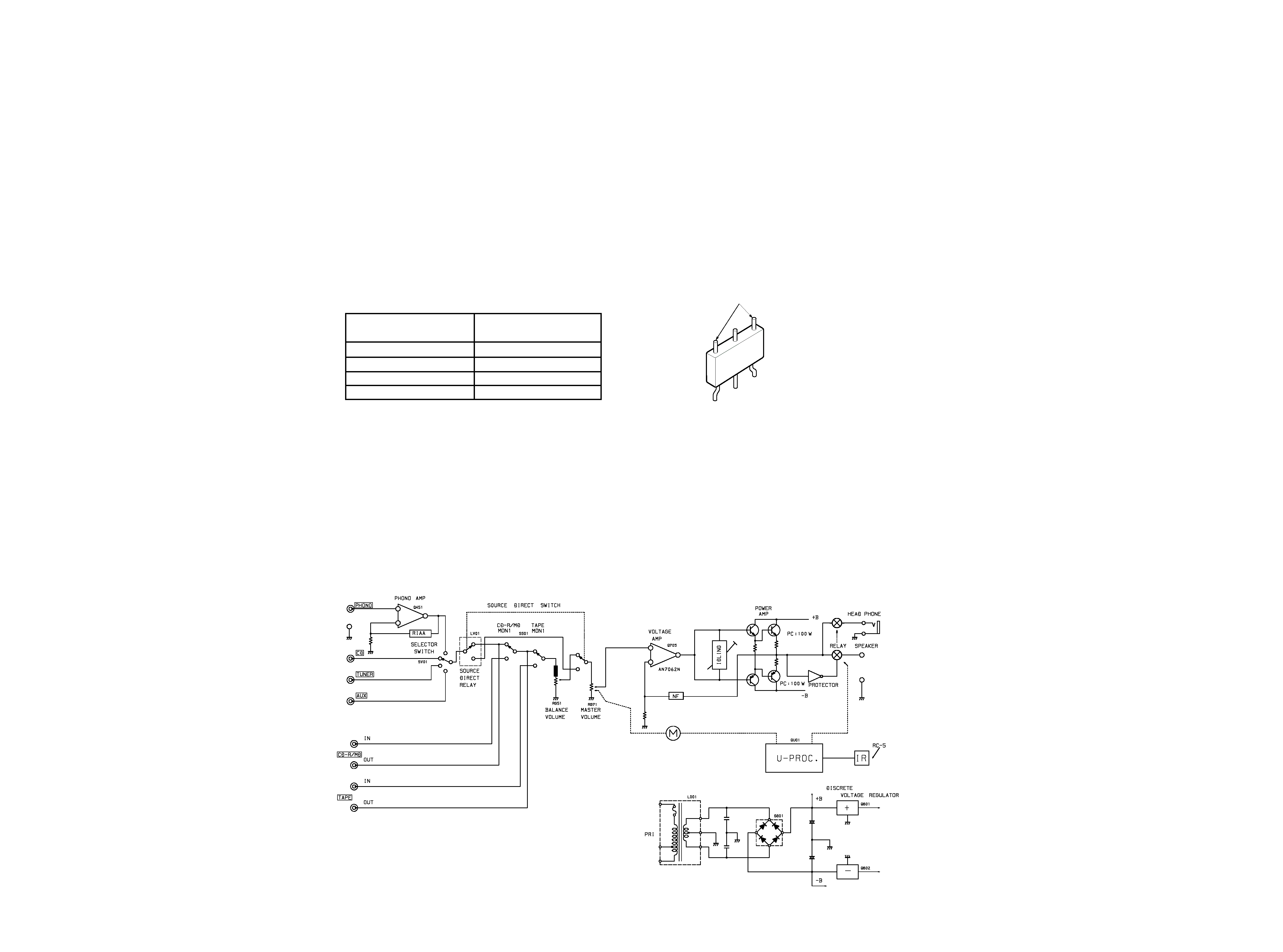
4. BLOCK DIAGRAM
3. IDLING CURRENT ADJUSTMENT
1.
Before switching the power ON, set the master volume
control to the minim um position and the balance
volume to the center positions. Also set semi-fixed
resistors R755(L ch) and R756(R ch) on PCB P701 to
the center positions.
2.
Each of the cement resistors R767(L ch) and R768(R
ch) on the PCB P701 is provided with three test points.
Connect a digital voltmeter, set for the DC voltage
input, to the test points at the two extremities of the
three test points of R767 or R768.
3.
After the setup above, switch the power ON, and adjust
semi-fixed resistors R755(L ch) and R756(R ch) on PCB
P701 according to the digital voltmeter reading. The
target setting value is 10 mV(50 mA) for both the L ch
and R ch.
Please refer to the table below.
Measurement point
R767 / R768
Elapsed time
Idling current
after Mains ON
setting value
30 sec. - 1 min.
3 ± 1 mV
1 min. - 2 min.
6 ± 1 mV
2 min. - 4 min.
8 ± 1 mV
More than 5 min.
10 ± 2 mV
3
4
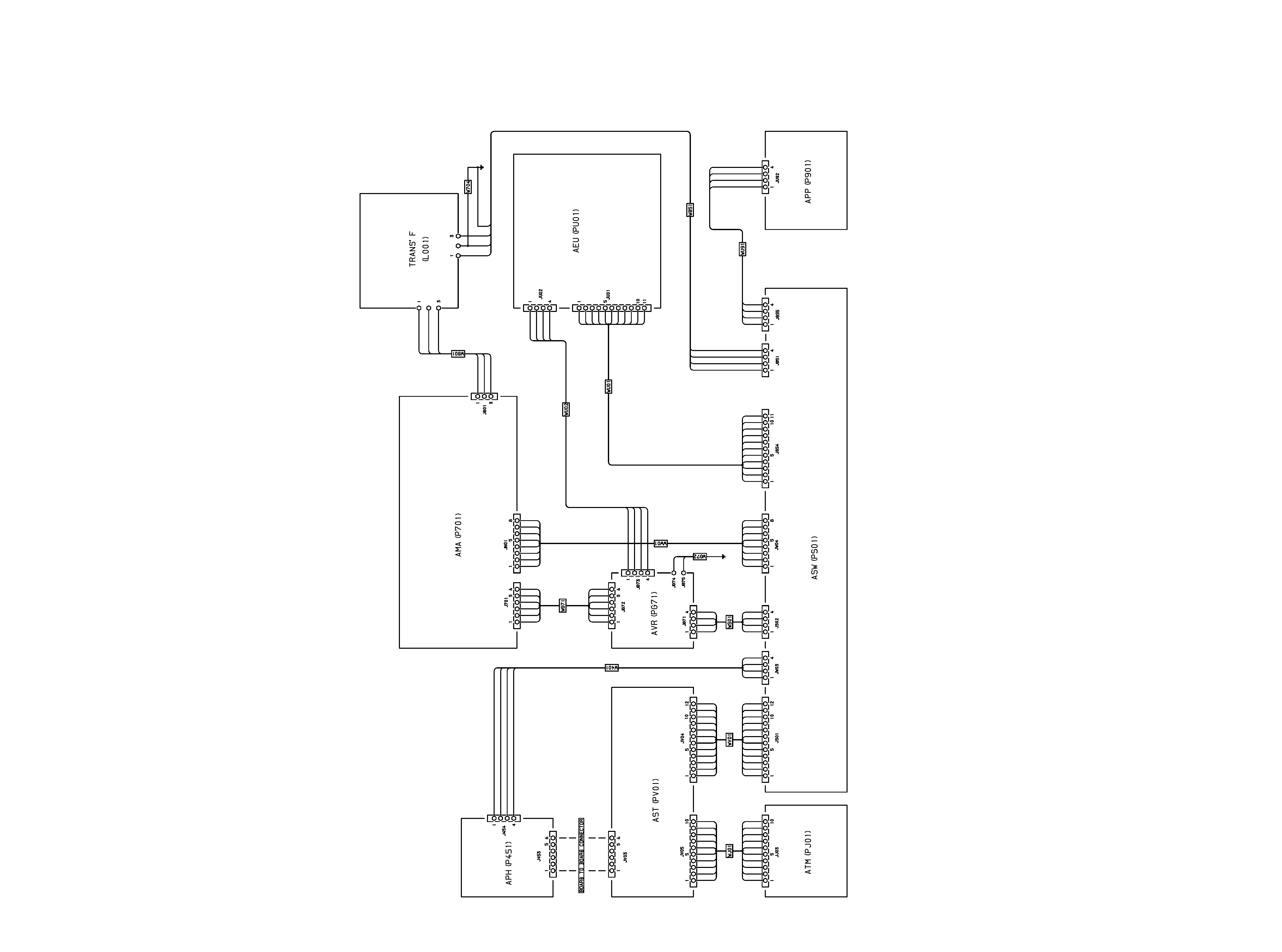
5. WIRING DIAGRAM