DR110
326W855020 MIT
3120 785 22740
First Issue 2002.02
Service
Manual
R
Please use this service manual with referring to the user guide ( D.F.U. ) without fail.
DR110 /F1S/N1S
Compact Disc Recorder
TABLE OF CONTENTS
SECTION
PAGE
1. TECHNICAL SPECIFICATIONS ........................................................................... 1
2. SERVICE PROCEDURE ...................................................................................... 2
3. WIRING DIAGRAM ............................................................................................... 3
4. BLOCK DIAGRAM ................................................................................................ 5
5. SCHEMATIC DIAGRAM ....................................................................................... 7
6. PARTS LOCATION (Pattern Side) ....................................................................... 9
7. IC DATA .............................................................................................................. 13
8. EXPLODED VIEW AND PARTS LIST ................................................................ 19
9. ELECTRICAL PARTS LIST ................................................................................ 22
MULTI JOG
PUSH ENTER
DISPLAY
SOURCE
FINALIZE
MENU
DUBB.
ERASE
REC
DR110
OPTICAL
COAXIAL
ANALOG
SYNC MP3
REC
HI
CD
R
W
R
L
dB
40 30 20 15 10 6
3
0 OVER
PROG
TIMER
REPEAT
FINAL RANDOM
SCAN
AB
ALL
AUTO
TRACK
TRACK
TIME
TOTAL
REM
FADE
STANDBY
OPEN
STANDBY
OPEN
DR110
MARANTZ DESIGN AND SERVICE
Using superior design and selected high grade components,
MARANTZ company has created the ultimate in stereo sound.
Only original
MARANTZ parts can insure that your MARANTZ product will continue to perform to the specifications for which
it is famous.
Parts for your
MARANTZ equipment are generally available to our National Marantz Subsidiary or Agent.
ORDERING PARTS :
Parts can be ordered either by mail or by Fax.. In both cases, the correct part number has to be specified.
The following information must be supplied to eliminate delays in processing your order :
1. Complete address
2. Complete part numbers and quantities required
3. Description of parts
4. Model number for which part is required
5. Way of shipment
6. Signature : any order form or Fax. must be signed, otherwise such part order will be considered as null and void.
SHOCK, FIRE HAZARD SERVICE TEST :
CAUTION : After servicing this appliance and prior to returning to customer, measure the resistance between either primary AC
cord connector pins ( with unit NOT connected to AC mains and its Power switch ON ), and the face or Front Panel of product and
controls and chassis bottom.
Any resistance measurement less than 1 Megohms should cause unit to be repaired or corrected before AC power is applied, and
verified before it is return to the user/customer.
Ref. UL Standard No. 1492.
In case of difficulties, do not hesitate to contact the Technical
Department at above mentioned address.
020213MIT
SUPERSCOPE TECHNOLOGIES, INC.
USA
MARANTZ AMERICA, INC
1100 MAPLEWOOD DRIVE
ITASCA, IL. 60143
USA
PHONE : 630 - 741 - 0300
FAX
: 630 - 741 - 0301
BRAZIL
PHILIPS DA AMAZONIA IND. ELET. ITDA
CENTRO DE INFORMACOES AO
CEP 04698-970
SAO PAULO, SP, BRAZIL
PHONE : 0800 - 123123 (Discagem Direta Gratuita)
FAX
: +55 11 534. 8988
JAPAN Technical
MARANTZ JAPAN, INC.
35- 1, 7- CHOME, SAGAMIONO
SAGAMIHARA - SHI, KANAGAWA
JAPAN 228-8505
PHONE : +81 42 748 1013
FAX
: +81 42 741 9190
EUROPE / TRADING
MARANTZ EUROPE B.V.
P. O. BOX 8744, BUILDING SILVERPOINT
BEEMDSTRAAT 11, 5653 MA EINDHOVEN
THE NETHERLANDS
PHONE : +31 - 40 - 2507844
FAX
: +31 - 40 - 2507860
TECHNICAL AUDIO GROUP PTY, LTD
558 DARLING STREET,
BALMAIN, NSW 2041,
AUSTRALIA
PHONE : 61 - 2 - 9810 - 5300
FAX
: 61 - 2 - 9810 - 5355
CANADA
LENBROOK INDUSTRIES LIMITED
633 GRANITE COURT,
PICKERING, ONTARIO L1W 3K1
CANADA
PHONE : 905 - 831 - 6333
FAX
: 905 - 831 - 6936
AUSTRALIA
QualiFi Pty Ltd,
24 LIONEL ROAD,
MT. WAVERLEY VIC 3149
AUSTRALIA
PHONE : +61 - (0)3 - 9543 - 1522
FAX
: +61 - (0)3 - 9543 - 3677
NEW ZEALAND
WILDASH AUDIO SYSTEMS NZ
14 MALVERN ROAD MT ALBERT
AUCKLAND NEW ZEALAND
PHONE : +64 - 9 - 8451958
FAX
: +64 - 9 - 8463554
THAILAND
MRZ STANDARD CO., LTD
746 - 754 MAHACHAI ROAD.,
WANGBURAPAPIROM, PHRANAKORN,
BANGKOK, 10200 THAILAND
PHONE : +66 - 2 - 222 9181
FAX
: +66 - 2 - 224 6795
TAIWAN
PAI- YUING CO., LTD.
6 TH FL NO, 148 SUNG KIANG ROAD,
TAIPEI, 10429, TAIWAN R.O.C.
PHONE : +886 - 2 - 25221304
FAX
: +886 - 2 - 25630415
MALAYSIA
WO KEE HONG ELECTRONICS SDN. BHD.
SUITE 8.1, LEVEL 8, MENARA GENESIS,
NO. 33, JALAN SULTAN ISMAIL,
50250 KUALA LUMPUR, MALAYSIA
PHONE : +60 3 - 21457677
FAX
: +60 3 - 21458180
AMERICAS
MARANTZ PROFESSIONAL PRODUCTS
2640 WHITE OAK CIRCLE, SUITE A
AURORA, ILLINOIS 60504 USA
PHONE : 630 - 820 - 4800
FAX
: 630 - 820 - 8103
AUSTRALIA
KOREA
MK ENTERPRISES LTD.
ROOM 604/605, ELECTRO-OFFICETEL, 16-58,
3GA, HANGANG-RO, YONGSAN-KU, SEOUL
KOREA
PHONE : +822 - 3232 - 155
FAX
: +822 - 3232 - 154
SINGAPORE
WO KEE HONG DISTRIBUTION PTE LTD
130 JOO SENG ROAD
#03-02 OLIVINE BUILDING
SINGAPORE 368357
PHONE : +65 858 5535 / +65 381 8621
FAX
: +65 858 6078

1
1. TECHNICAL SPECIFICATIONS
GENERAL
System ........................................................................................................................... Compact disc digital audio
Number of channels .................................................................................................................................. 2 (stereo)
Applicable discs ............................................................................ CD, CD-R (digital audio), CD-RW (digital audio)
Power Requirement ................................................................................................ AC 100V 50 / 60Hz (F version)
AC 230 V 50 Hz (N version)
Power Consumption .......................................................................................................................................... 16W
Operating Temperature .............................................................................................................................. 5 - 35 °C
DIMENSION (MAX)
Width ........................................................................................................................................................... 210 mm
Height ......................................................................................................................................................... 71.5 mm
Depth ........................................................................................................................................................... 310 mm
Weight ............................................................................................................................................................ 3.8 Kg
AUDIO
Frequency Response ....................................................................................................................... 20 Hz - 20 kHz
Playback S/N ................................................................................................................................................... 90 dB
Playback Dynamic Range ............................................................................................................................... 85 dB
Playback Total Harmonic Distortion .............................................................................................................. 0.04 %
Recording S/N ................................................................................................................................................. 90 dB
Recording Dynamic Range ............................................................................................................................. 85 dB
Recording Total Harmonic Distortion ............................................................................................................ 0.04 %
Line Output Voltage ....................................................................................................................................... 2 Vrms
RECORDING VALUES FOR LINE INPUT
Digital Coaxial Input (automatic sample rate conversion) ...................................................................... 32 - 48 kHz
Digital Optical Input (automatic sample rate conversion) ....................................................................... 32 - 48 kHz
Analog Input .............................................................................................................................. 250 mVrms/ 50 kW
ACCESSORIES
Remote Control Unit (RC110DRMD) ..................................................................................................................... 1
Dimensions (W x H x D) .................................................................................................... 50.5 x 54.5 x 25 mm
Weight .......................................................................................................................................................... 60 g
AA Type Batteries .................................................................................................................................................. 2
Stereo Audio Cable ......................................................................................................................................... 1 pair
Coaxial Cable ......................................................................................................................................................... 1
Remote Cable ........................................................................................................................................................ 1
Specifications subject to change without prior notice.
2
Service Mode
1.
While Mains cord is disconnected, press STOP button on the unit and plug in the Mains cord.
2.
Version number of the front micom software is displayed.
3.
Turn JOG dial clockwise then Display Segment test begins.
4.
First all the segments will light and then a segment turns off one by one.
5.
Disconnect Mains cord to quit service mode.
Emergency Eject
1.
To open the tray when it is stuck, insert a pin into the eject pinhole and push.
2.
Use a pin
4mm or less.
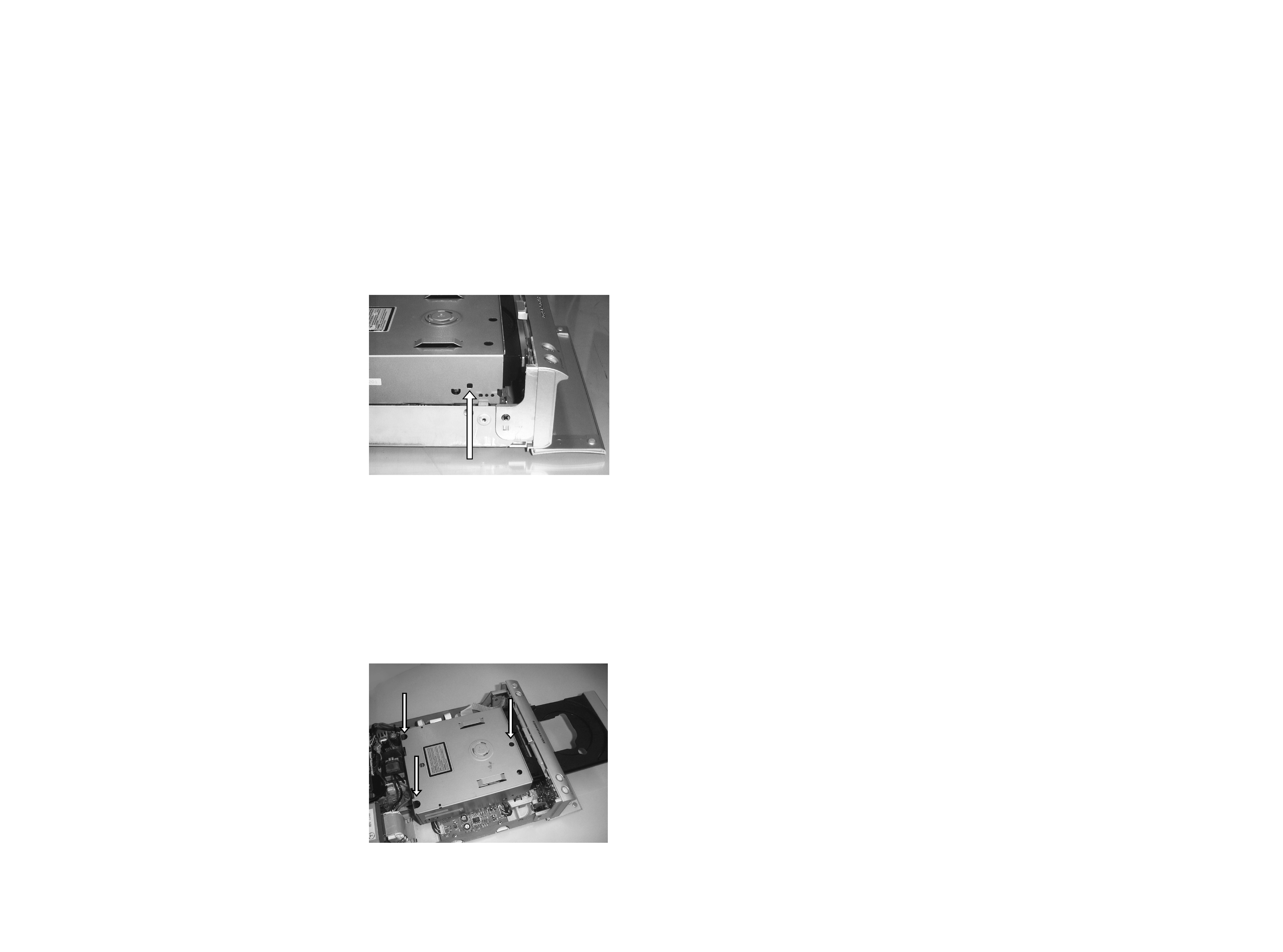
2. SERVICE PROCEDURE
Replacing the Mechanism Assy
1.
Open the tray first.
2.
Remove the 3 screws shown in the picture below.
3.
Disconnect all the wires at the right side.
4.
Replace the MECHANISM ASSY.
5.
Afer replacing the MECHANISM ASSY, insert a CD-R/RW, record something and FINALIZE it. It MUST be done
to set it's particular R-ID to the new MECHANISM ASSY.
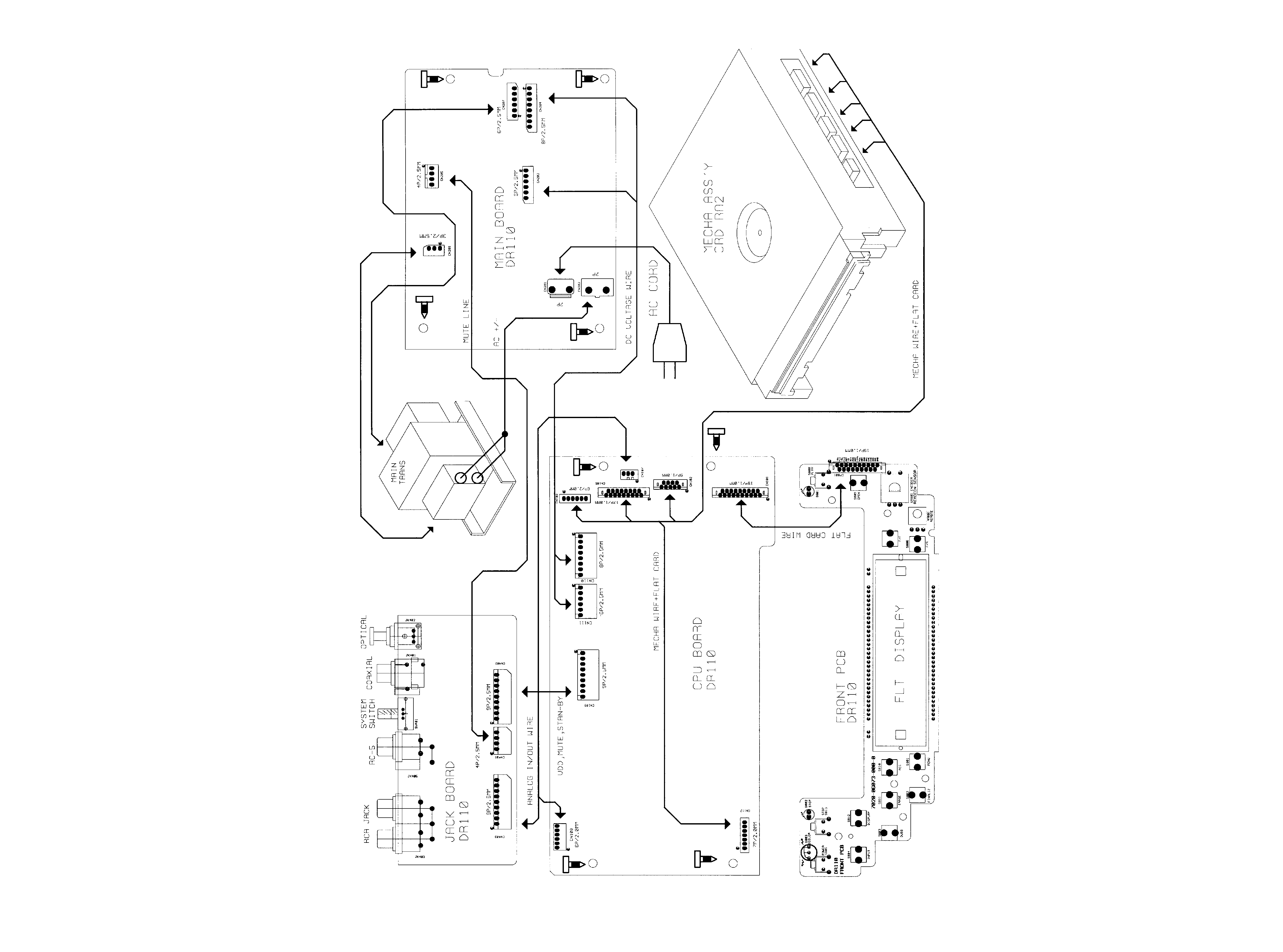
3
4
3. WIRING DIAGRAM