
OWNER'S MANUAL
AND WARRANTY REGISTRATION
EFX
MON
HI
12kHz
HI
12kHz
MID
2.5kHz
MON
MID
2.5kHz
MON
HI
12kHz
MID
2.5kHz
MON
HI
12kHz
MID
2.5kHz
MON
HI
12kHz
MID
2.5kHz
MON
HI
12kHz
MID
2.5kHz
MON
HI
12kHz
MID
2.5kHz
MON
HI
12kHz
MID
2.5kHz
LOW
80Hz
PAN
PAN
PAN
PAN
PAN
PAN
PAN
PAN
VOLUME
CH.
VOLUME
CH.
VOLUME
CH.
VOLUME
CH.
VOLUME
CH.
VOLUME
CH.
VOLUME
CH.
VOLUME
CH.
1
EFX
LOW
80Hz
2
2
EFX
LOW
80Hz
3
3
EFX
LOW
80Hz
4
4
EFX
LOW
80Hz
5
5
EFX
LOW
80Hz
6
6
EFX
LOW
80Hz
7
8
7
EFX
LOW
80Hz
8
EFX
BYPASS
EFX
DRIVE
LEVEL
12
0
NORMAL
INPUT
LEVEL
SET
INPUT
LEVEL
SET
INPUT
LEVEL
SET
INPUT
LEVEL
SET
INPUT
LEVEL
SET
INPUT
LEVEL
SET
INPUT
LEVEL
SET
INPUT
LEVEL
SET
EFX
CLIP
PARAMETERS
10
0
10
0
REVERBS
DELAYS
CHORUS
FLANGE
DAMPING
DEPTH
PHASER
TIME
RATE
NORMAL
NORMAL
CUSTOM
32-BIT
PRECISION
DIGITAL
STEREO
EFFECTS
PROCESSING
EFX
WIDE
MAIN-STEREO/MONO
EQUALIZER
30
CLIP
5
5
0
10
15
20
EFX
FOOT
SWITCH
RIGHT
RETURN
LEFT
RETURN
SEND
L
MIXER
OUT
R
MIXER
OUT
C
OMPRESSOR
L
POWER
AMP
IN
R
POWER
AMP
IN
EFFECTS
(OVERRIDES
INTERNAL
EFX)
MONITOR
MAINS
TAPE
IN
TAPE
OUT
LEVEL
MIC
1
MIC
2
MIC
3
MIC
4
MIC
5
MIC
6
INSERT
INSERT
INSERT
INSERT
INSERT
LINE
LINE
LINE
LINE
LINE
LINE
INSERT
+15
U
O
O
1K
500
250
63
125
16K
LEVEL
2K
4K
8K
MAIN
MASTER
EFX
TO
MAIN
U
O
O
+10
MASTER
OUTPUT
SECTION
LINE
U
+12dB
O
O
L
R
R
L
POWER
OUT
MONITOR
EQUALIZER
15-
15+
5
10
0
5
10
-15
+15
5
10
0
5
10
15-
15+
5
10
0
5
10
-15
+15
5
10
0
5
10
1K
500
250
63
125
16K
2K
4K
8K
MONITOR
MASTER
EFX
TO
MON
U
O
O
+10
U
+12dB
O
O
75Hz
RUMBLE
REDUCTION
LEFT/MONO
RIGHT
LEFT/MONO
RIGHT
MIC
7
MIC
8
75Hz
RUMBLE
REDUCTION
PHANTOM
POWER
CH
1
-8
BREAK
(MUTES
CH
1-6)
808S
POWER
AMP
ROUTING
STEREO
MIC/
LINE
HI-Z
STEREO
MIC/
LINE
HI-Z
SM.
ROOM
MD.
PLATE
LG.
PLATE
LG.
HALL
GATED
REVERSE
CATHEDRAL
MD.
HALL
SPRING
PHASER
DELAY
4
CHORUS
DELAY
3
DELAY
1
FLANGE
DELAY
2
IN
OUT
STEREO
MAINS
LEFT
=
MAIN
RIGHT
=
MONITOR
2
X
600W
STEREO
LEVEL
30
CLIP
5
5
0
10
15
20
LR
U
O
O
+10
U
+1
5
-1
5
U
+1
5
-1
5
U
+12
-12
1
U
+20dB
O
O
HI
LOW
NORMAL
U
O
O
+15
U
O
O
+10
U
+1
5
-1
5
U
+1
5
-1
5
U
+12
-12
U
+20dB
O
O
HI
LOW
NORMAL
U
O
O
+15
U
O
O
+10
U
+1
5
-1
5
U
+1
5
-1
5
U
+12
-12
U
+20dB
O
O
HI
LOW
NORMAL
U
O
O
+15
U
O
O
+10
U
+1
5
-1
5
U
+1
5
-1
5
U
+12
-12
U
+20dB
O
O
HI
LOW
NORMAL
U
O
O
+15
U
O
O
+10
U
+1
5
-1
5
U
+1
5
-1
5
U
+12
-12
U
+20dB
O
O
HI
LOW
NORMAL
U
O
O
+15
U
O
O
+10
U
+1
5
-1
5
U
+1
5
-1
5
U
+12
-12
U
+20dB
O
O
HI
LOW
NORMAL
U
O
O
+15
U
O
O
+10
U
+1
5
-1
5
U
+1
5
-1
5
U
+12
-12
U
+20dB
O
O
HI
LOW
NORMAL
U
O
O
+15
U
O
O
+10
U
+1
5
-1
5
U
+1
5
-1
5
U
+12
-12
U
+20dB
O
O
HI
LOW
NORMAL
R
L
R
L
R
L
R
L
R
L
R
L
R
L
R
L
U
O
O
+15
CAUTION
AVIS
RISK OF ELECTRIC
SHOCK
DO NOT OPEN
RISQUE DE CHOC ELECTRIQUE
NE PAS OUVRIR
CAUTION: TO REDUCE THE RISK OF ELECTRIC SHOCK
DO NOT REMOVE COVER (OR BACK)
NO USER-SERVICEABLE PARTS INSIDE
REFER SERVICING TO QUALIFIED PERSONNEL
ATTENTION: POUR EVITER LES RISQUES DE CHOC
ELECTRIQUE, NE PAS ENLEVER LE COUVERCLE. AUCUN
ENTRETIEN DE PIECES INTERIEURES PAR L'USAGER. CONFIER
L'ENTRETIEN AU PERSONNEL QUALIFIE.
AVIS: POUR EVITER LES RISQUES D'INCENDIE OU
D'ELECTROCUTION, N'EXPOSEZ PAS CET ARTICLE
A LA PLUIE OU A L'HUMIDITE
The lightning flash with arrowhead symbol within an equilateral
triangle is intended to alert the user to the presence of uninsulated
"dangerous voltage" within the product's enclosure that may be
of sufficient magnitude to constitute a risk of electric shock to persons.
Le symbole éclair avec point de flèche à l'intérieur d'un triangle
équilatéral est utilisé pour alerter l'utilisateur de la présence à
l'intérieur du coffret de "voltage dangereux" non isolé d'ampleur
suffisante pour constituer un risque d'éléctrocution.
The exclamation point within an equilateral triangle is intended to
alert the user of the presence of important operating and maintenance
(servicing) instructions in the literature accompanying the appliance.
Le point d'exclamation à l'intérieur d'un triangle équilatéral est
employé pour alerter les utilisateurs de la présence d'instructions
importantes pour le fonctionnement et l'entretien (service) dans le
livret d'instruction accompagnant l'appareil.
7. Heat -- This Mackie product should be situated away from heat
sources such as radiators, or other devices which produce heat.
8. Power Sources -- This Mackie product should be connected to a
power supply only of the type described in these operation
instructions or as marked on this Mackie product.
9. Power Cord Protection -- Power supply cords should be routed
so that they are not likely to be walked upon or pinched by items
placed upon or against them, paying particular attention to cords at
plugs, convenience receptacles, and the point where they exit this
Mackie product.
10. Object and Liquid Entry -- Care should be taken so that
objects do not fall into and liquids are not spilled into this Mackie
product.
11. Damage Requiring Service -- This Mackie product should be
serviced only by qualified service personnel when:
A. The power-supply cord or the plug has been
damaged; or
B. Objects have fallen, or liquid has spilled into this
Mackie product; or
C. This Mackie product has been exposed to rain; or
D. This Mackie product does not appear to operate
normally or exhibits a marked change in performance;
or
E. This Mackie product has been dropped, or its chassis
damaged.
12. Servicing -- The user should not attempt to service this
Mackie product beyond those means described in this operating
manual. All other servicing should be referred to the Mackie Service
Department.
13. To prevent electric shock, do not use this polarized plug with an
extension cord, receptacle or other outlet unless the blades can be
fully inserted to prevent blade exposure.
Pour préevenir les chocs électriques ne pas utiliser cette fiche
polariseé avec un prolongateur, un prise de courant ou une autre
sortie de courant, sauf si les lames peuvent être insérées à fond
sans laisser aucune pariie à découvert.
14. Grounding or Polarization -- Precautions should be taken so
that the grounding or polarization means of this Mackie product is
not defeated.
15. This apparatus does not exceed the Class A/Class B (whichever
is applicable) limits for radio noise emissions from digital apparatus
as set out in the radio interference regulations of the Canadian
Department of Communications.
ATTENTION --Le présent appareil numérique n'émet pas de bruits
radioélectriques dépassant las limites applicables aux appareils
numériques de class A/de class B (selon le cas) prescrites dans le
règlement sur le brouillage radioélectrique édicté par les ministere
des communications du Canada.
SAFETY INSTRUCTIONS
1. Read Instructions -- All the safety and operation instructions
should be read before this Mackie product is operated.
2. Retain Instructions -- The safety and operating instructions
should be kept for future reference.
3. Heed Warnings -- All warnings on this Mackie product and in
these operating instructions should be followed.
4. Follow Instructions -- All operating and other instructions
should be followed.
5. Water and Moisture -- This Mackie product should not be used
near water for example, near a bathtub, washbowl, kitchen sink,
laundry tub, in a wet basement, near a swimming pool, swamp or
salivating St. Bernard dog, etc.
6. Ventilation -- This Mackie product should be situated so
that its location or position does not interfere with its proper
ventilation. For example, the Component should not be situated
on a bed, sofa, rug, or similar surface that may block any
ventilation openings, or placed in a built-in installation such as a
bookcase or cabinet that may impede the flow of air through
ventilation openings.
PORTABLE CART WARNING
Carts and stands - The
Component should be used
only with a cart or stand
that is recommended by
the manufacturer.
A Component and cart
combination should be
moved with care. Quick
stops, excessive force, and
uneven surfaces may cause
the Component and cart
combination to overturn.
WARNING -- To reduce the risk of fire or electric
shock, do not expose this appliance to rain or moisture.

3
Part No. 820-077-00 Rev. A 1/99
©1999 Mackie Designs Inc. All Rights Reserved. Printed in the U.S.A.
Lend Me Your Ears
Exposure to extremely
high noise levels may cause
permanent hearing loss.
Individuals vary
considerably in
susceptibility to noise-induced hearing loss,
but nearly everyone will lose some hearing if
exposed to sufficiently intense noise for a period
of time. The U.S. Government's Occupational
Safety and Health Administration (OSHA) has
specified the permissible noise level exposures
shown in this chart.
®
According to OSHA, any exposure in excess
of these permissible limits could result in some
hearing loss. To ensure against potentially
dangerous exposure to high sound-pressure
levels, it is recommended that all persons
exposed to equipment capable of producing
these levels use hearing protectors while this
unit is in operation. Ear plugs or protectors in
the ear canals or over the ears must be worn
when operating this amplification system in
order to prevent a permanent hearing loss if
exposure is in excess of the limits set forth here.
Duration Per Day
Sound Level dBA,
Typical
In Hours
Slow Response
Example
8
90
Duo in small club
692
4
95
Subway Train
397
2
100
Very loud classical music
1.5
102
1
105
Lori screaming at Ron about deadlines
0.5
110
0.25 or less
115
Loudest parts at a rock concert
4
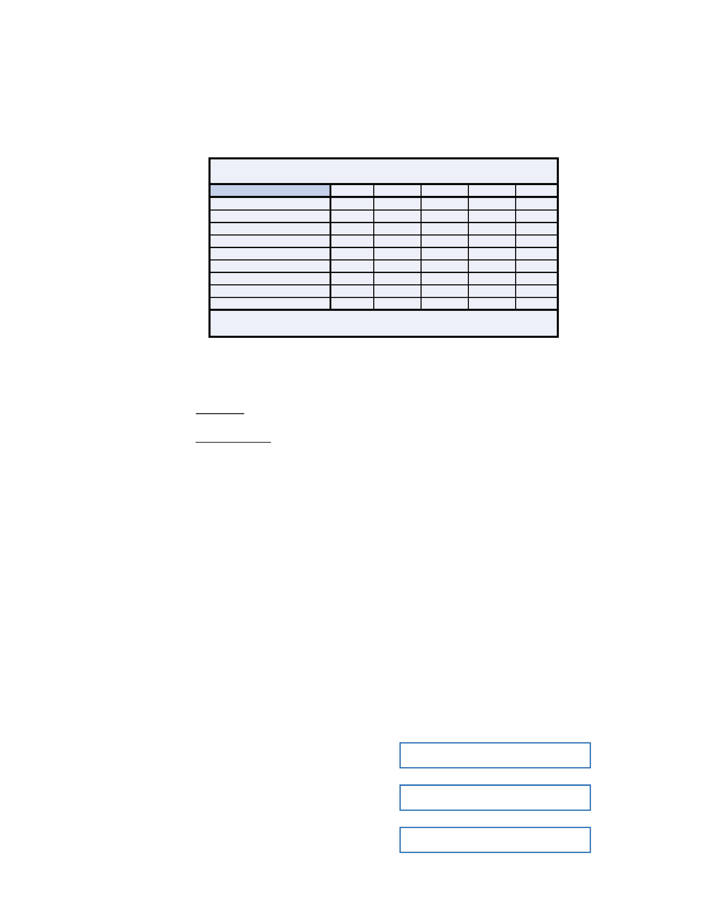
INTRODUCTION
406M
408M
808M
408S
808S
6 Mono Channels
2 Mono/Stereo Channels
*
*
Pan Controls
Effects Return(s)
1
1
1
2
2
Tape Inputs
*
*
*
Tape Outputs
**
**
**
Mixer Line Output(s)
1
1
1
2
2
Two 250W Amplifiers
Two 600W Amplifiers
** Summed to Main Bus
** Mono Tape Outputs
PPM Series Features
In addition, the PPM Series boast solid design
features such as:
·
Two FR SeriesTM (Fast Recovery)
power amplifiers
808M/808S
1200 total watts (600 watts x 2 into 2 ohms)
406M/408M/408S
500 total watts (250 watts x 2 into 2 ohms)
·
Built-in compressor to prevent clipping
·
Two built-in graphic equalizers for Mains
and Monitors
·
Two switchable low-cut Rumble Reduction
filters for Mains and Monitors
·
EMACTM custom 32-bit precision digital
stereo effects processor
·
Global phantom power switch
·
Exclusive Break switch mutes channels 1-6
while break music is playing
·
Power amp routing switch selects main out
only or main on one output and monitor on
the other output
·
3-band EQ on each channel
·
Monitor and Effects send on each channel
·
Balanced/unbalanced 1/4" and XLR inputs
on each channel
·
1/4" Insert jacks on channels 1-6
·
1/4" Mixer line output(s) and Monitor line
output
·
1/4" Power Amp line inputs
·
Two 1/4" Speaker outputs per side
·
RCA stereo Tape In and Tape Out
·
Three year warranty
At Mackie, we know what it takes to be
roadworthy. After all, our mixers have traveled
all over the world under the worst of conditions,
and we've applied what we've learned to the
mechanical design of our powered mixers.
Reliability is paramount to sound reinforce-
ment. That's why our engineers have subjected
our powered mixers to the most rigorous and
fiendish tests imaginable to fine-tune the
design and extend its limits beyond those of
ordinary mixers or amplifiers.
Our Fast Recovery (FR) amplifiers used in
the Professional Powered Mixer Series perform
better than conventional designs when present-
ed with adverse conditions such as clipping.
Conventional designs use lots of negative feed-
back to provide stability and lower distortion.
When clipping occurs, this "feedback" causes
high-frequency sticking, keeping the amplifier
"latched" in the clipping state longer than
necessary. This results in painfully audible
distortion. The Fast Recovery design eliminates
this high-frequency sticking and allows the
amplifier to remain stable when powering
highly reactive loads at high volume levels.
Please read the "Quick Start" section on
page 6. It gives an overview of the powered mixer,
and the rest of the manual explains the wealth of
features and operating instructions in more detail.
Please write your serial number here for
future reference (i.e., insurance claims, tech
support, return authorization, etc.):
Purchased at:
Date of purchase:
Thank you for choosing a Mackie Designs
PPM SeriesTM Powered Mixer! These powerful,
compact mixers are designed to meet the
needs of almost any small to medium-sized
club/meeting room/sanctuary/outdoor
gathering.
This chart illustrates the differences be-
tween the various models at a glance:

5
CONTENTS
INTRODUCTION ...................................................4
QUICK START .................................................6
APPLICATION DIAGRAMS ................................7
FEATURES AND CONTROLS .................................. 14
Channel Strip Description............................... 14
INPUT LEVEL SET .................................... 14
VOLUME ............................................... 14
PAN ..................................................... 14
LOW EQ ................................................ 14
MID EQ ................................................. 14
HI EQ.................................................... 14
EFX Send .............................................. 15
MON Send ............................................ 15
EMAC Section Description .............................. 15
EFX DRIVE LEVEL ................................... 15
EFX CLIP ............................................... 15
EFX BYPASS .......................................... 15
EFX WIDE ............................................. 16
Preset Select ......................................... 16
TIME/RATE PARAMETER ......................... 18
DAMPING/DEPTH PARAMETER ............... 18
MASTER OUTPUT SECTION Description ........... 18
POWER LED........................................... 18
MONITOR EQUALIZER ............................ 18
MAIN EQUALIZER .................................. 18
75Hz RUMBLE REDUCTION ...................... 18
EFX TO MON ......................................... 19
MONITOR MASTER ................................. 19
EFX TO MAIN ........................................ 19
MAIN MASTER ....................................... 19
LEVEL Meters ......................................... 19
PHANTOM POWER Switch ...................... 19
BREAK Switch ........................................ 20
POWER AMP ROUTING .......................... 20
COMPRESSOR........................................ 20
TAPE IN LEVEL ........................................ 21
POWER Switch ....................................... 21
MAKING THE CONNECTIONS ............................... 22
Front Panel Connections ................................ 22
Connecting Microphones
and
Line-Level Signals
......................... 22
Channel Inserts ....................................... 22
EFFECTS SEND and RETURN ...................... 23
EFX FOOT SWITCH .................................. 24
POWER AMP IN 1 and 2 ......................... 24
MIXER LINE OUT .................................... 24
MONITOR LINE OUT ............................... 24
TAPE IN and TAPE OUT ............................ 24
Rear Panel Connections ................................. 25
SPEAKER OUT ........................................ 25
IEC Socket ............................................. 25
GENERAL PRECAUTIONS AND CONSIDERATIONS .... 26
Thermal Considerations ................................. 26
AC Power Considerations .............................. 26
APPENDIX A: Service Info ................................... 27
Warranty Service ......................................... 27
Troubleshooting ........................................... 27
Repair ........................................................ 28
APPENDIX B: Some Arcane Mysteries Illuminated ... 29
Balanced Lines ............................................. 29
Unbalancing a Line ....................................... 29
Grounding................................................... 30
APPENDIX C: Technical Info .................................. 31
Specifications .............................................. 31
Contributors and Colophon ............................ 32
Block Diagrams ............................................ 33
PPM SERIES LIMITED WARRANTY ........................ 35
PRODUCT REGISTRATION CARD........................... 35
Attached to
back cover
Don't forget to visit our website at www.mackie.com
for more information about these and other Mackie products.
®