M·2600
OWNER'S MANUAL
HIGH-CURRENT POWER AMPLIFIER
TM
O
L
3
6
9
2
0
3
6
9
2
0
S
IG
O
L
S
IG
C
H
1
3
3
3
1
2
9
2
3
2
5
2
1
2
7
1
9
1
7
1
1
3
3
3
1
2
9
2
3
2
5
2
1
2
7
1
9
1
7
1
1
0
0
1
.2
3
v
(+
4
d
B
u
)
S
E
N
S
IT
IV
IT
Y
G
A
IN
/d
B
C
H
2
P
R
O
T
E
C
T
C
O
LD
H
O
T
S
H
O
R
T
T
E
M
P
S
T
A
T
U
S
IN
T
E
R
N
A
L
S
T
A
T
U
S
C
H
1
C
H
2
C
H
1
&
2
O
N
O
F
F
P
O
W
E
R
3
v
2v
1v
0
0
1
.2
3
v
(+
4
d
B
u
)
S
E
N
S
IT
IV
IT
Y
G
A
IN
/d
B
3
v
2v
1v
P
R
O
F
E
S
S
IO
N
A
L
P
O
W
E
R
A
M
P
LI
F
IE
R
FU
LL
SY
M
M
E
TR
Y
D
U
A
L
D
IF
FE
RE
N
TI
A
L
H
IG
H
C
U
R
RE
N
T
D
E
SI
G
N
SERIAL
NUMBER
MANUF
A
CTURING
D
A
TE
RISK
O
F
ELECTRIC
SH
O
C
K
D
O
NO
T
O
PEN
CAUTION
2600
W
A
TTS
4
OHM
LOAD
MIN.
1
20
V
AC
60
Hz
200
0
W
A
T
T
S
STEREO
TYPICAL
CH
1
CH
2
+
+
MONO BRIDGE
·THE
FOLLOWING
ARE
REGISTERED
TR
A
DEMARKS
O
F
M
ACK
IE
DESIGN
INC.:
"MACKIE",
"FR
SERIES",
AND
THE
"RUNNING
MAN"
FIGURE
·
CONCEIVED,
DESIGNED,
AND
MANUFACTURED
BY
MACKIE
DESIGNS
INC
·
WO
ODINVILLE
WA
·
98072
·
USA
·
MADE
IN
USA
·
PATENTS
PENDING
·
COPYRIGHT
©1998
1300
W
A
T
TS
/
CH
2
OHM
LOAD
MIN.
1
CHANNEL
MONO
BRIDGE
SUB
WO
OF
ER
TYPICAL 35
Hz
CH
A
NNEL
2
ON
T
YPICAL
CAUTION
LETHAL
VOLTAGES
MAY
APPEAR
AT
OUTPUT
TERMINALS.
CLASS
1
WIRING
IS
REQUIRED
SPE
A
K
ER
OU
T
P
U
T
S
IN
IN
LOW
CUT
FILTER
INPUT
INPUT
CROSSOVER
SWITCHED
OUTPUT
SWITCHED
OUTPUT
BAL
ANCED OR
UNBAL
ANCED
170
Hz
100
Hz
OFF
STAGE
MONITOR
90Hz
LOW OUT
HIGH OUT
THRU
LOW OUT
HIGH OUT
THRU
120Hz
60Hz
CROSSOVER
90Hz
120Hz
60Hz
AMP
MODE
BRIDGED
MONO
O
U
T
P
U
T
APPLI
C
A
T
IO
N
BAL
ANCED OR
UNBAL
ANCED
LIMITER
(CH1
&
CH2)
LOW
OUT
(SUB
WOOFER)
OFF
CH's
SUMMED
FULL RANGE
LOW
CUT
FILTER
170
Hz
100
Hz
OFF
STAGE
MONITOR
SUB
WO
OF
ER
TYPICAL 35
Hz
W
ARNIN
G:
TO
REDUCE
THE
RISK
OF
FIRE
OR
ELECTRIC
SHOCK,
DO
NOT
EX
POSE
THIS
EQUIPMENT
TO
RAIN
OR
MOISTURE.
DO
NOT
REMOVE
COVER.
NO
USER
SERVICEABLE
PARTS
INSIDE.
REFER
SERVICING
T
OQUALIFIED
PERSONNEL.
AVIS:
RISQUE
DE
CHOC
ELECTRIQUE
--
NE
P
AS
OUVRIR
PIN
1
+
CH1
+
PIN
1
CH1
PIN
2
+
&
2
NOT
USED
PIN
1
+
CH2+
PIN
1
CH2
PIN
2
+
&
2
NOT
USED
PIN
1+
BRIDGE
+
PIN
1
BRIDGE
PIN
2
+
&
2
NOT
USED
TH
RU
TH
RU
CAUTION
AVIS
RISK OF ELECTRIC
SHOCK
DO NOT OPEN
RISQUE DE CHOC ELECTRIQUE
NE PAS OUVRIR
CAUTION: TO REDUCE THE RISK OF ELECTRIC SHOCK
DO NOT REMOVE COVER (OR BACK)
NO USER-SERVICEABLE PARTS INSIDE
REFER SERVICING TO QUALIFIED PERSONNEL
ATTENTION: POUR EVITER LES RISQUES DE CHOC
ELECTRIQUE, NE PAS ENLEVER LE COUVERCLE. AUCUN
ENTRETIEN DE PIECES INTERIEURES PAR L'USAGER. CONFIER
L'ENTRETIEN AU PERSONNEL QUALIFIE.
AVIS: POUR EVITER LES RISQUES D'INCENDIE OU
D'ELECTROCUTION, N'EXPOSEZ PAS CET ARTICLE
A LA PLUIE OU A L'HUMIDITE
The lightning flash with arrowhead symbol within an equilateral
triangle is intended to alert the user to the presence of uninsulated
"dangerous voltage" within the product's enclosure, that may be
of sufficient magnitude to constitute a risk of electric shock to persons.
Le symbole éclair avec point de flèche à l'intérieur d'un triangle
équilatéral est utilisé pour alerter l'utilisateur de la présence à
l'intérieur du coffret de "voltage dangereux" non isolé d'ampleur
suffisante pour constituer un risque d'éléctrocution.
The exclamation point within an equilateral triangle is intended to
alert the user of the presence of important operating and maintenance
(servicing) instructions in the literature accompanying the appliance.
Le point d'exclamation à l'intérieur d'un triangle équilatéral est
employé pour alerter les utilisateurs de la présence d'instructions
importantes pour le fonctionnement et l'entretien (service) dans le
livret d'instruction accompagnant l'appareil.
7. Heat -- This Mackie product should be situated away from heat
sources such as radiators, or other devices which produce heat.
8. Power Sources -- This Mackie product should be connected to a
power supply only of the type described in these operation
instructions or as marked on this Mackie product.
9. Power Cord Protection -- Power supply cords should be routed
so that they are not likely to be walked upon or pinched by items
placed upon or against them, paying particular attention to cords at
plugs, convenience receptacles, and the point where they exit this
Mackie product.
10. Object and Liquid Entry -- Care should be taken so that
objects do not fall into and liquids are not spilled into this Mackie
product.
11. Damage Requiring Service -- This Mackie product should be
serviced only by qualified service personnel when:
A. The power-supply cord or the plug has been
damaged; or
B. Objects have fallen, or liquid has spilled into this
Mackie product; or
C. This Mackie product has been exposed to rain; or
D. This Mackie product does not appear to operate
normally or exhibits a marked change in performance;
or
E. This Mackie product has been dropped, or its chassis
damaged.
12. Servicing -- The user should not attempt to service this
Mackie product beyond those means described in this operating
manual. All other servicing should be referred to the Mackie Service
Department.
13. To prevent electric shock, do not use this polarized plug with an
extension cord, receptacle or other outlet unless the blades can be
fully inserted to prevent blade exposure.
Pour préevenir les chocs électriques ne pas utiliser cette fiche
polariseé avec un prolongateur, un prise de courant ou une autre
sortie de courant, sauf si les lames peuvent être insérées à fond
sans laisser aucune pariie à découvert.
14. Grounding or Polarization -- Precautions should be taken so
that the grounding or polarization means of this Mackie product is
not defeated.
15. This apparatus does not exceed the Class A/Class B (whichever
is applicable) limits for radio noise emissions from digital apparatus
as set out in the radio interference regulations of the Canadian
Department of Communications.
ATTENTION --Le présent appareil numérique n'émet pas de bruits
radioélectriques dépassant las limites applicables aux appareils
numériques de class A/de class B (selon le cas) prescrites dans le
règlement sur le brouillage radioélectrique édicté par les ministere
des communications du Canada.
SAFETY INSTRUCTIONS
1. Read Instructions -- All the safety and operation instructions
should be read before this Mackie product is operated.
2. Retain Instructions -- The safety and operating instructions
should be kept for future reference.
3. Heed Warnings -- All warnings on this Mackie product and in
these operating instructions should be followed.
4. Follow Instructions -- All operating and other instructions
should be followed.
5. Water and Moisture -- This Mackie product should not be used
near water for example, near a bathtub, washbowl, kitchen sink,
laundry tub, in a wet basement, near a swimming pool, swamp or
salivating St. Bernard dog, etc.
6. Ventilation -- This Mackie product should be situated so
that its location or position does not interfere with its proper
ventilation. For example, the Component should not be situated
on a bed, sofa, rug, or similar surface that may block any
ventilation openings, or placed in a built-in installation such as a
bookcase or cabinet that may impede the flow of air through
ventilation openings.
PORTABLE CART WARNING
Carts and stands - The
Component should be used
only with a cart or stand
that is recommended by
the manufacturer.
A Component and cart
combination should be
moved with care. Quick
stops, excessive force, and
uneven surfaces may cause
the Component and cart
combination to overturn.
WARNING -- To reduce the risk of fire or electric shock,
do not expose this appliance to rain or moisture.
3
Part No. 820-078-00 Rev. A 10/98
©1998 Mackie Designs, All Rights Reserved. Printed in the U.S.A.
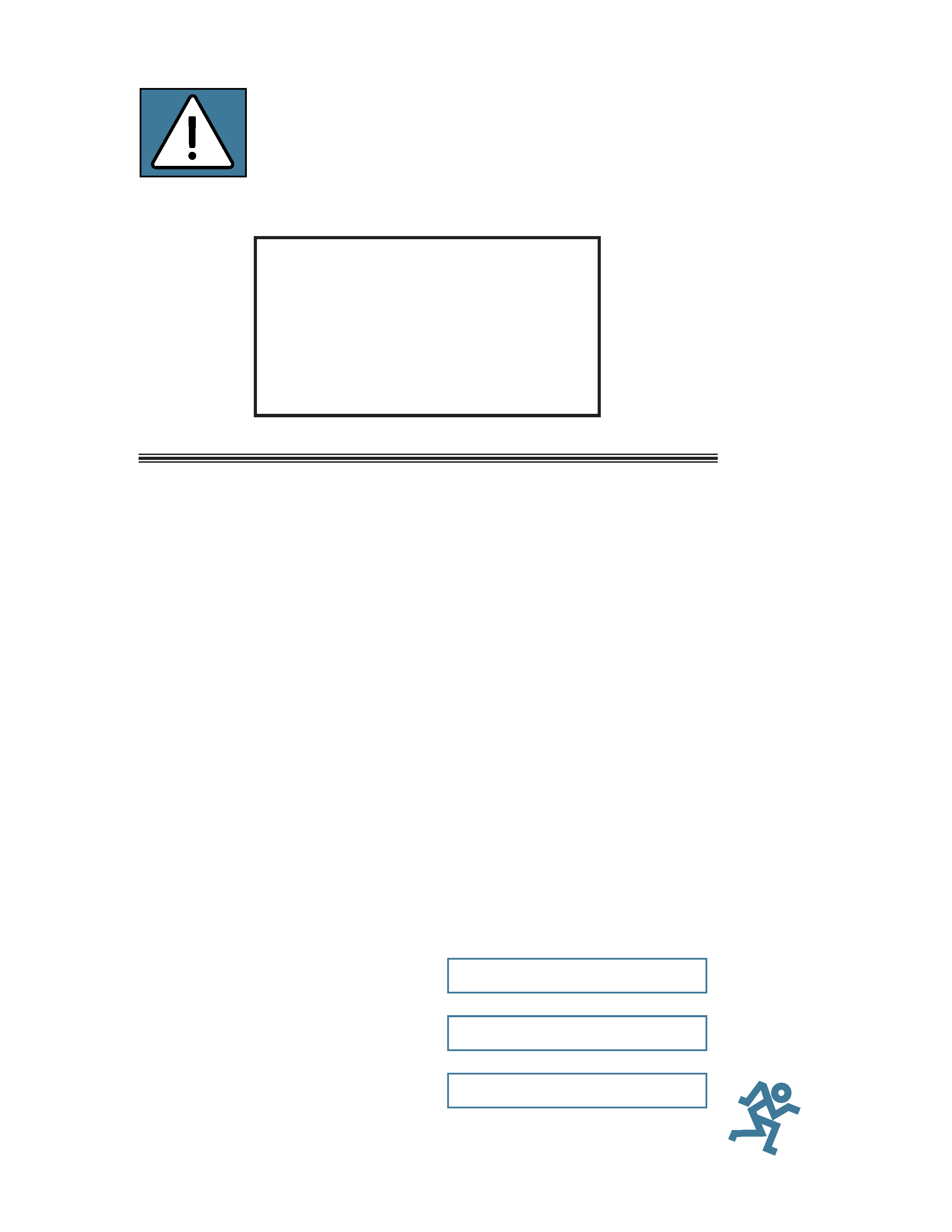
Lend Me Your Ears
Exposure to extremely high
noise levels may cause per-
manent hearing loss.
Individuals vary considerably
in susceptibility to noise-
induced hearing loss, but nearly everyone will
lose some hearing if exposed to sufficiently intense
noise for a period of
time. The U.S.
Government's Occu-
pational Safety and
Health Administra-
tion (OSHA) has
specified the per-
missible noise level
exposures shown in
this chart.
®
According to OSHA, any exposure in excess of
these permissible limits could result in some hear-
ing loss. To ensure against potentially dangerous
exposure to high sound pressure levels, it is recom-
mended that all persons exposed to equipment
capable of producing these levels (such as the
M·2600) use hearing protectors while this unit is in
operation. Ear plugs or protectors in the ear canals
or over the ears
must be worn when
operating this am-
plification system
in order to prevent
a permanent hear-
ing loss if exposure
is in excess of the
limits set forth here.
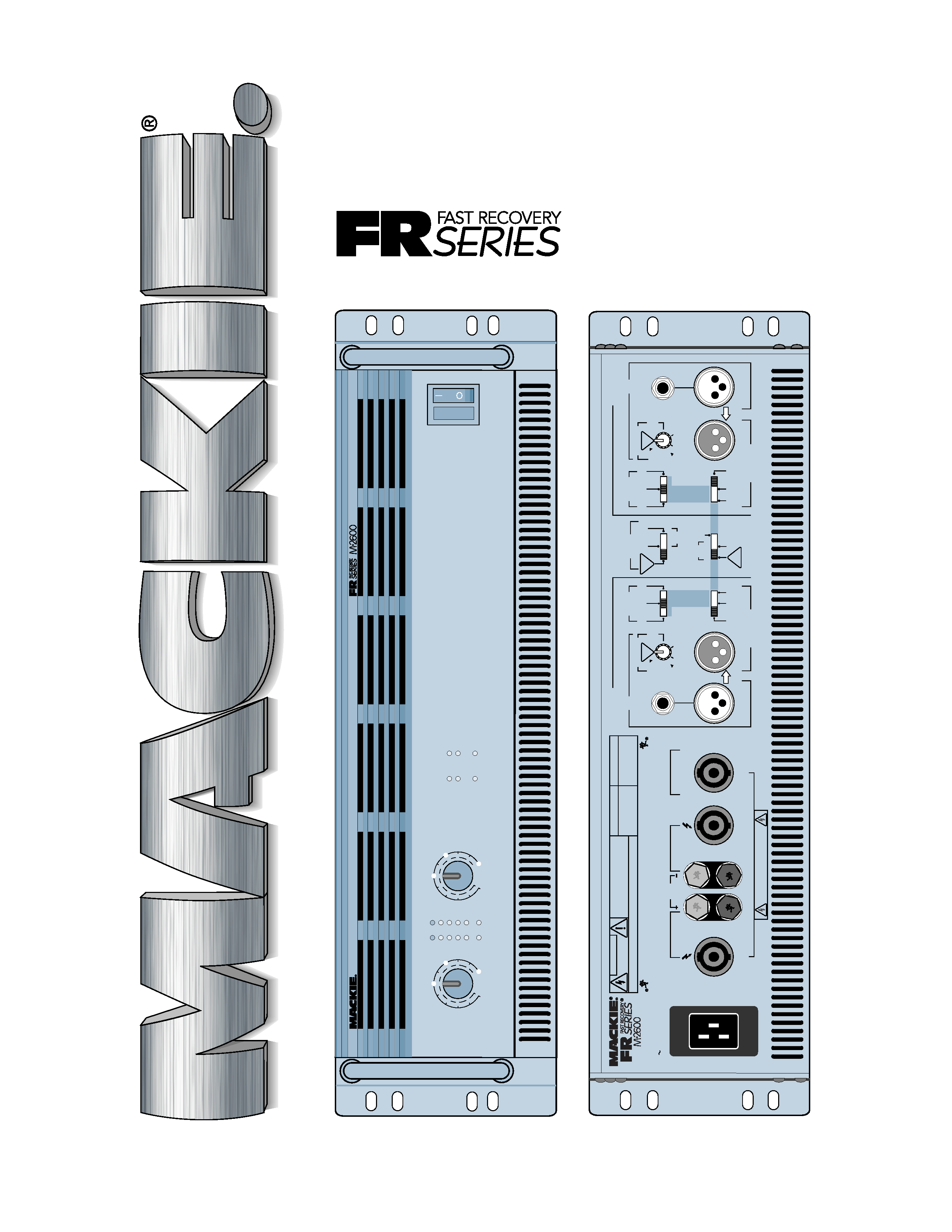
INTRODUCTION
Our Fast Recovery (FR) amplifiers perform
better than conventional designs when presented
with adverse conditions such as clipping. Con-
ventional designs use lots of negative feedback
to provide stability and lower distortion. When
clipping occurs, this "feedback" causes high-
frequency sticking, keeping the amplifier
"latched" in the clipping state longer than
necessary. This results in painfully audible
distortion. The Fast Recovery design eliminates
this high-frequency sticking and allows the
amplifier to remain stable when powering
highly reactive loads at high volume levels.
Carefully read and follow all the safety in-
structions explained on page 2 and throughout
the manual. The Quick Start guide on page 4
gives an overview of the amplifier, and the rest
of the manual explains the wealth of features
and operating instructions in loving detail.
Please write your serial number here for
future reference (i.e., insurance claims, tech
support, return authorization, etc.):
Purchased at:
Date of purchase:
Thank you for choosing a Mackie Designs
power amplifier! The M·2600 is designed to
fulfill the amplification needs of almost any type
of application, with solid design features such as:
· 2600 watts into 4 ohms, bridged
· 1700 watts into 8 ohms, bridged
· 1300 watts x 2 into 2 ohms, stereo
· 850 watts x 2 into 4 ohms, stereo
· 500 watts x 2 into 8 ohms, stereo
· Easily handles 2 ohm loads all night long
· Two low-cut filters, 2nd-order Bessel,
12dB/octave, variable from Off to 170Hz
· Two superior design active crossovers,
4th-order Linkwitz-Riley, 24dB/octave,
selectable crossover point at 60, 90 or 120Hz
· Switchable limiter
· Automatic soft turn-on and multiple
protection circuits
· Balanced/unbalanced 1/4" and XLR inputs
· XLR thru outputs, selectable to full-range,
high pass or low pass
· Speakon® or binding post outputs
· Superior T-Design fan cooling
· Ultra low noise and distortion
· Fast Recovery design
· Five year warranty
At Mackie, we know what it takes to be
roadworthy. After all, our mixers have traveled
all over the world under the worst of conditions,
and we've applied what we've learned to the
mechanical design of our amplifiers.
Reliability is paramount to sound reinforce-
ment. That's why we use double-sided thru-hole-
plated fiberglass printed circuit boards. That's
why our engineers have subjected the amplifier
to the most rigorous and fiendish tests imag-
inable to fine-tune the design and extend its
limits beyond those of ordinary amplifiers.
Duration in
Sound level dBA
Typical example
hours per day (slow response)
8
90
Duo in small club
692
4
95
Subway Train
397
2
100
Very loud classical music
1.5
102
1
105
Lori screaming at Ron
0.5
110
0.25 or less
115
Loudest parts at a rock concert
4
READ THIS PAGE!
5. Determine which
AMP MODE
is best
for your application:
·
STEREO mode (separate left and right
inputs, separate left and right outputs) is
the typical setup for amplifying stereo
signals.
·
MONO mode (sometimes called Dual-
Mono mode -- one or two inputs, two mono
outputs) is for sending a mono signal to
two different speaker sets, with separately-
adjustable level controls.
·
BRIDGED mode (sometimes called
Bridged-Mono -- one or two inputs, one
mono output) uses both sides of the amp to
triple the power going to one speaker. An
M·2600 in
BRIDGED mode, delivers 2600
watts (into 4 ohms). Garsh!
Note: In
BRIDGED mode, 4 ohms is the mini-
mum speaker impedance you should connect to
the amplifier. If you connect a lower impedance
load, the amplifier may go into
PROTECT
mode and the
SHORT
LEDs will turn on.
Then the audience will turn on you.
6. In
STEREO mode, connect line-level cables
from your signal source to the M·2600's
INPUT
jacks, either XLR or TRS:
· The XLR and TRS inputs for each
channel are wired in parallel.
· The balanced XLR inputs are wired
pin 2 = hot (+), pin 3 = cold (), and
pin 1 = shield (ground).
· The 1/4" TRS inputs are wired
tip = hot (+), ring = cold (), and
sleeve = shield (ground), and can accept
either balanced (TRS) or unbalanced (TS)
cables.
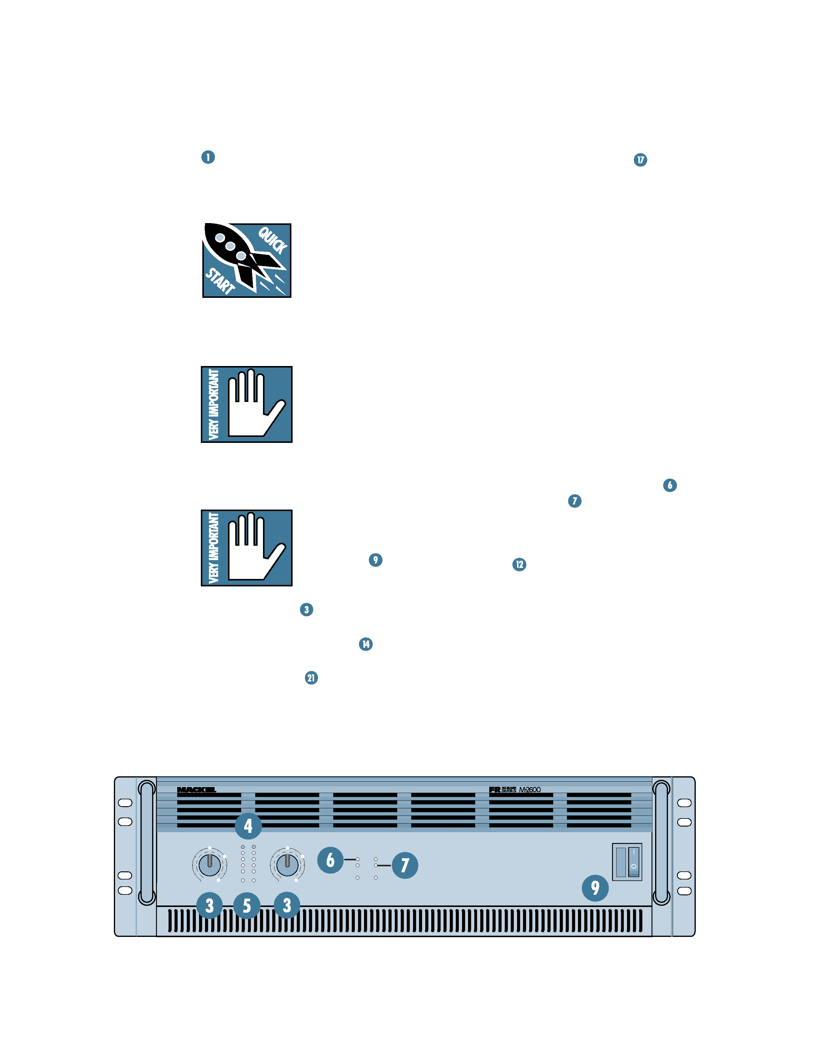
QUICK START
I got ants in my pants and I got to dance!
INSTALLATION
You can mount the M·2600
amp in any standard rack
system (see page 29), or
place it horizontally on a
floor or table. The heavier
internal components are
located towards the front of the chassis to make
it easier to hold the amp by its front handles.
The M·2600 amp draws its
ventilation air in from the
front and out through the
side panels. It needs plenty
of fresh air to stay cool.
DO NOT BLOCK THE VENTILATION PORTS
(see page 29).
CONNECTIONS AND SETTINGS
1. The output terminals
are capable of high voltage
output, so for your safety,
the
POWER
switch
must be off before making
any connections.
2. Turn the
GAIN
controls fully down
(counterclockwise) for now.
3. Set both
LOW CUT FILTER
controls to
their
TYPICAL marks (35Hz).
4. Set the
LIMITER
switch on.
Note: If you're using the M·2600 to power a
subwoofer, you probably do not need an external
crossover. Please see page 28 for details.
OL
3
6
9
20
3
6
9
20
SIG
OL
SIG
CH
1
33
31
29
23
25
21
27
19
17
11
33
31
29
23
25
21
27
19
17
11
0 0
1.23v (+4dBu)
SENSITIVITY
GAIN/dB
CH
2
PROTECT
COLD
HOT
SHORT
TEMP STATUS
INTERNAL STATUS
CH
1
CH
2
CH
1& 2
ON
OFF
POWER
3v
2v
1v
0 0
1.23v (+4dBu)
SENSITIVITY
GAIN/dB
3v
2v
1v
PROFESSIONAL POWER AMPLIFIER
FULL SYMMETRY DUAL DIFFERENTIAL HIGH CURRENT DESIGN
5
SERIAL NUMBER
MANUFACTURING DATE
RISK OF ELECTRIC SHOCK
DO NOT OPEN
CAUTION
2600 WATTS
4 OHM LOAD MIN.
120 VAC 60 Hz
2000 WATTS
STEREO
TYPICAL
CH
1
CH
2
+
+
MONO
BRIDGE
· THE FOLLOWING ARE REGISTERED TRADEMARKS OF MACKIE DESIGN INC.: "MACKIE", "FR SERIES", AND THE "RUNNING MAN" FIGURE ·
CONCEIVED, DESIGNED, AND MANUFACTURED BY MACKIE DESIGNS INC · WOODINVILLE
WA · 98072 · USA · MADE IN USA · PATENTS PENDING · COPYRIGHT ©1998
1300 WATTS / CH
2 OHM LOAD MIN.
1 CHANNEL
MONO
BRIDGE
SU
B
W
O
O
FE
R
TYPICAL
35 Hz
CHANNEL
2
ON
TYPICAL
CAUTION
LETHAL VOLTAGES MAY APPEAR AT OUTPUT
TERMINALS. CLASS 1 WIRING IS REQUIRED
SPEAKER OUTPUTS
IN
IN
LOW CUT FILTER
INPUT
INPUT
CROSSOVER
SWITCHED OUTPUT
SWITCHED OUTPUT
BALANCED
OR
UNBALANCED
170 Hz
100 Hz
OFF
STAGE
MONITOR
90Hz
LOW
OUT
HIGH
OUT
THRU
LOW
OUT
HIGH
OUT
THRU
120Hz
60Hz
CROSSOVER
90Hz
120Hz
60Hz
AMP MODE
BRIDGED
MONO
OUTPUT APPLICATION
BALANCED
OR
UNBALANCED
LIMITER
(CH1 & CH2)
LOW OUT
(SUB WOOFER)
OFF
CH's
SUMMED
FULL
RANGE
LOW CUT FILTER
170 Hz
100 Hz
OFF
STAGE
MONITOR
SU
B
W
O
O
FE
R
TYPICAL
35 Hz
WARNING: TO REDUCE THE RISK OF FIRE OR ELECTRIC SHOCK, DO NOT
EXPOSE THIS EQUIPMENT TO RAIN OR MOISTURE. DO NOT REMOVE COVER.
NO USER SERVICEABLE PARTS INSIDE. REFER SERVICING TO QUALIFIED PERSONNEL.
AVIS: RISQUE DE CHOC ELECTRIQUE -- NE PAS OUVRIR
PIN 1+ CH1+
PIN 1 CH1
PIN 2+ & 2 NOT USED
PIN 1+ CH2+
PIN 1 CH2
PIN 2+ & 2 NOT USED
PIN 1+ BRIDGE+
PIN 1 BRIDGE
PIN 2+ & 2 NOT USED
THRU
THRU
7. In
BRIDGED mode, connect an input cable
to
CHANNEL 1's INPUT or CHANNEL 2. If
you want to use both inputs, the two input
signals are summed internally to produce a
mono signal.
8. In
STEREO and MONO modes, connect
speaker cables to the
SPEAKER OUTPUTS
, using either the binding post or
Speakon® connectors.
· The binding post connectors are wired
red = hot (+) and black = cold ().
· See page 40 for Speakon wiring details.
9. In
BRIDGED mode, connect the speaker
cable like this: the positive (+) wire goes in
the
CHANNEL 1 SPEAKER OUTPUT's red
post and the negative () wire goes in
CHANNEL 2's red post. Plug nothing into
the black posts. There is also a single
Speakon connector for
BRIDGED mode
(see page 40).
10. Connect the other ends of the speaker
cables to your loudspeakers.
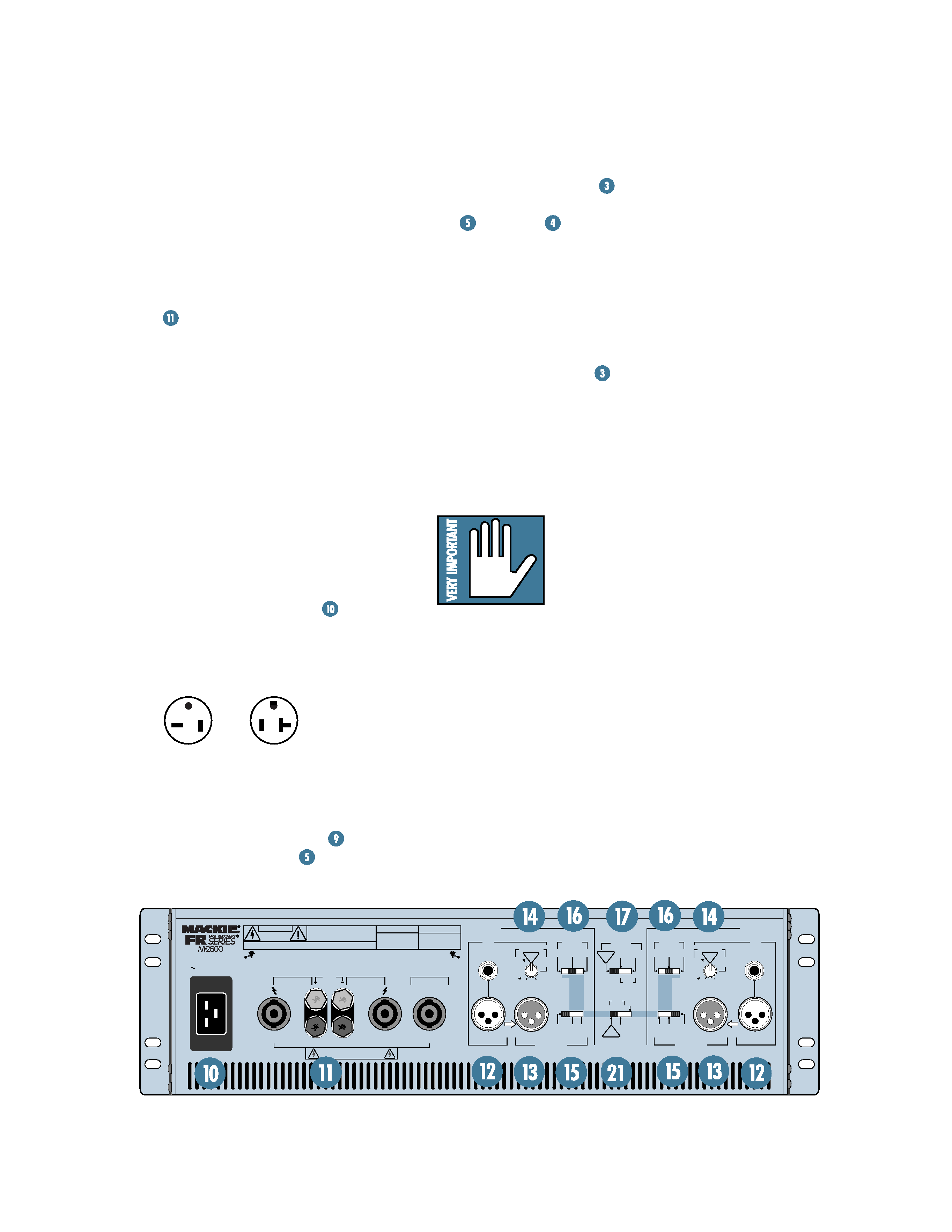
11. Plug the amp's power cord
into a
3-prong AC outlet properly configured for
the type of plug supplied with your amplifier,
and capable of delivering at least 20 amps
(for the 120V model).
12. Make sure your signal source (feeding the
M·2600's inputs) is powered up and
delivering signal to the amp.
13. Turn the M·2600's
POWER
switch on
and verify that the
SIG
LEDs are
showing an input signal is present.
14. Slowly turn both
GAIN
controls up:
You should hear the music and see the
SIG
and meter
LEDs flashing.
If the topmost LEDs (named
OL, for
overload) are flashing, turn down either
the
GAIN controls on the amp or the
source signal's output level controls (i.e.,
master faders). The point is: The
OL LEDs
should not light up.
15. For quieter listening, it is preferable to
adjust the amp's
GAIN
controls rather
than the source signal's output level
(unless you have the source's control all
the way up!).
16. Start dancing, but don't let the ants out of
your pants.
Things You Must Remember:
· Never plug amplifier
outputs into anything
except speakers (unless
you have an outboard box
specifically designed to
handle high-power
speaker-level signals).
·
Before making connections to an amp or
reconfiguring an amp's routing, turn the
amp's level (
GAIN) controls down, turn
the power off, make the changes, turn
the power back on, and then turn the
level controls back up.
·
If you shut down your equipment, turn
off the amplifiers first. When powering
up, turn on the amplifiers last.
·
Save the shipping boxes! You may need
them someday, and you probably don't
want to have to pay for them again.
GG
NEMA 5-20P
(Plug supplied with
120 VAC models)
NEMA 5-20R
(120 VAC, 20Amp
Receptacle)