
CFX SERIES
OWNER'S MANUAL
AND WARRANTY REGISTRATION
12, 16, AND 20-CHANNEL
MIC/LINE MIXERS
WITH DIGITAL EFFECTS
CLIP
WIDE
BYPASS
10
0
10
0
REVERBS
DELAYS
CHORUS/FLANGE/PHASER
DAMPING
DEPTH
TIME
RATE
NORMAL
NORMAL
EFX
SM. ROOM
MD. PLATE
LG. PLATE
LG. HALL
GATED
REVERSE
CATHEDRAL
MD. HALL
SPRING
PHASER
DELAY 4
CHORUS
DELAY 3
DELAY 1
FLANGE
DELAY 2
1
3-4
1-2
MUTE
CLIP
0dB=0dBu
LEFT RIGHT
MID
400Hz
MID
400Hz
U
+15
O
O
U
+15
O
O
U
+15
O
O
U
+15
O
O
1
2
600
1.5k
150
8k
100
12k
HI
MID
FREQ
80Hz
LOW
EQ
U
+15
-15
U
+15
-15
U
+15
-15
600
1.5k
150
8k
100
12k
HI
MID
FREQ
80Hz
LOW
EQ
U
+15
-15
U
+15
-15
U
+15
-15
600
1.5k
150
8k
100
12k
HI
MID
FREQ
80Hz
LOW
EQ
U
+15
-15
U
+15
-15
U
+15
-15
600
1.5k
150
8k
100
12k
HI
MID
FREQ
80Hz
LOW
EQ
U
+15
-15
U
+15
-15
U
+15
-15
600
1.5k
150
8k
100
12k
HI
MID
FREQ
80Hz
LOW
EQ
U
+15
-15
U
+15
-15
U
+15
-15
600
1.5k
150
8k
100
12k
HI
MID
FREQ
80Hz
LOW
EQ
U
+15
-15
U
+15
-15
U
+15
-15
600
1.5k
150
8k
100
12k
HI
MID
FREQ
80Hz
LOW
EQ
U
+15
-15
U
+15
-15
U
+15
-15
600
1.5k
150
8k
100
12k
HI
MID
FREQ
80Hz
LOW
EQ
U
+15
-15
U
+15
-15
U
+15
-15
ASSIGN
SUB
1
MIC
1
BAL/UNBAL
LINE IN
INSERT
BAL/UNBAL
LINE IN
INSERT
BAL/UNBAL
LINE IN
INSERT
BAL/UNBAL
LINE IN
INSERT
BAL/UNBAL
LINE IN
INSERT
BAL/UNBAL
LINE IN
INSERT
BAL/UNBAL
LINE IN
INSERT
BAL/UNBAL
LINE IN
INSERT
MIC
2
MIC
3
MIC
4
MIC
5
MIC
6
MIC
7
MIC
8
ZERO
LEVEL
SET
TAPE LEVEL
O
O
MAX
PHONES LEVEL
UTILITY OUT LEVEL
1
(EXT)
48v
LR
PAN
LR
PAN
LR
PAN
LR
PAN
LR
PAN
LR
PAN
LR
PAN
LR
PAN
LR
PAN
LR
PAN
RIGHT
LEFT
RIGHT
LEFT
RIGHT
LEFT
RIGHT
LEFT
3-4
1-2
MUTE
3-4
1-2
MUTE
3-4
1-2
MUTE
3-4
1-2
MUTE
3-4
1-2
MUTE
3-4
1-2
MUTE
3-4
1-2
MUTE
3-4
1-2
MUTE
3-4
1-2
MUTE
dB
30
20
10
O
O
40
50
5
5
U
60
10
SOLO
PFL
dB
30
20
10
O
O
40
50
5
5
U
60
10
SOLO
PFL
dB
30
20
10
O
O
40
50
5
5
U
60
10
SOLO
PFL
dB
30
20
10
O
O
40
50
5
5
U
60
10
SOLO
PFL
dB
30
20
10
O
O
40
50
5
5
U
60
10
SOLO
PFL
dB
30
20
10
O
O
40
50
5
5
U
60
10
SOLO
PFL
dB
30
20
10
O
O
40
50
5
5
U
60
10
SOLO
PFL
dB
30
20
10
O
O
40
50
5
5
U
60
10
SOLO
PFL
dB
30
20
10
O
O
40
50
5
5
U
60
10
SOLO
PFL
dB
30
20
10
O
O
40
50
5
5
U
60
10
SOLO
PFL
dB
30
20
10
O
O
40
50
5
5
U
60
10
dB
30
20
10
O
O
40
50
5
5
U
60
10
dB
30
20
10
O
O
40
50
5
5
U
60
10
dB
30
20
10
O
O
40
50
5
5
U
60
10
dB
30
20
10
O
O
40
50
5
5
U
60
10
15
15
5
10
0
5
10
15
15
5
10
0
5
10
1
EFX
2
(INT)
EFX
1
(EXT)
POWER
STATUS
RUDE
SOLO
BREAK SWITCH
(MUTES ALL CHANNELS)
PRE FADER
AUX
U
+15
O
O
U
+15
O
O
U
+15
O
O
U
+15
O
O
1
2
EFX
2
(INT)
EFX
1
(EXT)
PRE FADER
AUX
U
+15
O
O
U
+15
O
O
U
+15
O
O
U
+15
O
O
1
2
EFX
2
(INT)
EFX
1
(EXT)
PRE FADER
AUX
U
+15
O
O
U
+15
O
O
U
+15
O
O
U
+15
O
O
1
2
EFX
2
(INT)
EFX
1
(EXT)
PRE FADER
AUX
U
+15
O
O
U
+15
O
O
U
+15
O
O
U
+15
O
O
1
2
EFX
2
(INT)
EFX
1
(EXT)
PRE FADER
AUX
U
+15
O
O
U
+15
O
O
U
+15
O
O
U
+15
O
O
1
2
EFX
2
(INT)
EFX
1
(EXT)
PRE FADER
AUX
U
+15
O
O
U
+15
O
O
U
+15
O
O
U
+15
O
O
1
2
EFX
2
(INT)
EFX
1
(EXT)
PRE FADER
AUX
U
+15
O
O
U
+15
O
O
U
+15
O
O
U
+15
O
O
1
2
EFX
2
(INT)
EFX
1
(EXT)
PRE FADER
AUX
U
+15
O
O
U
+15
O
O
U
+15
O
O
U
+15
O
O
1
2
EFX
2
(INT)
EFX
1
(EXT)
PRE FADER
AUX
U
+15
O
O
U
+15
O
O
U
+15
O
O
U
+15
O
O
1
2
EFX
2
(INT)
EFX
1
(EXT)
PRE FADER
AUX
2
ASSIGN
2
3
ASSIGN
3
4
ASSIGN
4
5
ASSIGN
5
6
ASSIGN
6
7
ASSIGN
7
8
ASSIGN
8
9-10
ASSIGN
9
10
11-12
U
+15
O
O
U
+15
O
O
U
+15
O
O
U
+15
O
O
U
+20
O
O
U
+20
O
O
U
+10
O
O
U
+15
O
O
U
+15
O
O
U
+15
O
O
1
2
ASSIGN
ASSIGN
SUB
2
ASSIGN
SUB
3
ASSIGN
SUB
4
ASSIGN
11
12
AUX
EFX
MASTER SEND
U
TRIM
+20
-20
U
TRIM
+20
-20
LOW
LOW
22
10
7
4
2
0
2
4
7
10
20
30
STEREO
MAIN MIX
TRIM
LOW CUT
100 Hz
ZERO
LEVEL
M
IC GAIN
6
+50
U
-15dB +30dB
TRIM
LOW CUT
100 Hz
ZERO
LEVEL
M
IC GAIN
6
+50
U
-15dB +30dB
TRIM
LOW CUT
100 Hz
ZERO
LEVEL
M
IC GAIN
6
+50
U
-15dB +30dB
TRIM
LOW CUT
100 Hz
ZERO
LEVEL
M
IC GAIN
6
+50
U
-15dB +30dB
TRIM
LOW CUT
100 Hz
ZERO
LEVEL
M
IC GAIN
6
+50
U
-15dB +30dB
TRIM
LOW CUT
100 Hz
ZERO
LEVEL
M
IC GAIN
6
+50
U
-15dB +30dB
TRIM
LOW CUT
100 Hz
ZERO
LEVEL
M
IC GAIN
6
+50
U
-15dB +30dB
TRIM
LOW CUT
100 Hz
ZERO
LEVEL
M
IC GAIN
6
+50
U
-15dB +30dB
PHONES
FOOT
SWITCH
EFX
LAMP
12V 0.5A
MAIN OUT
L
R
11
LEFT
AUX SEND
UTILITY OUT
SUB OUT
TAPE
INPUT
TAPE
OUTPUT
LL
R
1
2
1
2
L
LR
R
L
R
EFX SEND
STEREO EFX
RETURN
MAIN INSERT
(MONO)
(MONO)
L
R
S
75Hz
SUB OUT
R
1
2
1
2
3
4
MAIN OUT
9
LEFT
RIGHT
10
RIGHT
12
EFX
1 RETURN
EFX 2 (INT) RETURN MASTERS
EFX
2
SEND
TO MAIN MIX
EFFECTS TO MONITOR
AUX
1
AUX
2
PHANTOM POWER
CFX 12 MIXER
STEREO GRAPHIC EQ
1K
500
250
63
125
16K
2K
4K
8K
12 CHANNEL COMPACT INTEGRATED LIVE SOUND MIXER
CUSTOM 32-BIT PRECISION
DIGITAL STEREO EFFECTS PROCESSOR
12k
HI
HI
MID
3k
80Hz
LOW
EQ
U
+15
-15
U
+15
-15
U
+15
-15
U
+15
-15
12k
HI
HI
MID
3k
80Hz
LOW
EQ
U
+15
-15
U
+15
-15
U
+15
-15
U
+15
-15
POWER
ON
120V, 60Hz, .85A
FUSE 1.25A, 250V SLOW
CFX12 MIXER
12 CHANNEL COMPACT INTEGRATED LIVE SOUND MIXER
SERIAL NUMBER
MANUFACTURING DATE
RISK OF ELECTRIC SHOCK
DO NOT OPEN
REPLACE WITH THE SAME TYPE FUSE AND RATING.
DISCONNECT SUPPLY CORD BEFORE CHANGING FUSE
UTILISE UN FUSIBLE DE RECHANGE DE MÊME TYPE.
DEBRANCHER AVANT DE REMPLACER LE FUSIBLE
WARNING: TO REDUCE THE RISK OF FIRE OR ELECTRIC SHOCK, DO NOT
EXPOSE THIS EQUIPMENT TO RAIN OR MOISTURE. DO NOT REMOVE COVER.
NO USER SERVICEABLE PARTS INSIDE. REFER SERVICING TO QUALIFIED PERSONNEL.
CAUTION
AVIS: RISQUE DE CHOC ELECTRIQUE -- NE PAS OUVRIR
CONCEIVED, DESIGNED, AND MANUFACTURED BY MACKIE DESIGNS INC · WOODINVILLE · WA · USA · MADE IN USA · FABRIQUE AU USA · COPYRIGHT ©1998 · THE
FOLLOWING ARE TRADEMARKS OR REGISTERED TRADEMARKS OF MACKIE DESIGNS INC.: "MACKIE", "EMAC", AND THE "RUNNING MAN" FIGURE · PATENT PENDING
TIP OUT TO EFFECTS DEVICE
RING RETURN FROM EFFECTS
STEREO
PLUG
FOR USE AS AN EFFECTS LOOP
(TIP= SEND, RING = RETURN)
DIRECT OUT WITH SIGNAL
INTERRUPTION TO MASTER
OPTIONAL USES FOR INSERTS
INSERT ALL THE WAY IN TO
THE "SECOND CLICK"
MONO PLUG
CAUTION
AVIS
RISK OF ELECTRIC
SHOCK
DO NOT OPEN
RISQUE DE CHOC ELECTRIQUE
NE PAS OUVRIR
CAUTION: TO REDUCE THE RISK OF ELECTRIC SHOCK
DO NOT REMOVE COVER (OR BACK)
NO USER-SERVICEABLE PARTS INSIDE
REFER SERVICING TO QUALIFIED PERSONNEL
ATTENTION: POUR EVITER LES RISQUES DE CHOC
ELECTRIQUE, NE PAS ENLEVER LE COUVERCLE. AUCUN
ENTRETIEN DE PIECES INTERIEURES PAR L'USAGER. CONFIER
L'ENTRETIEN AU PERSONNEL QUALIFIE.
AVIS: POUR EVITER LES RISQUES D'INCENDIE OU
D'ELECTROCUTION, N'EXPOSEZ PAS CET ARTICLE
A LA PLUIE OU A L'HUMIDITE
The lightning flash with arrowhead symbol within an equilateral
triangle is intended to alert the user to the presence of uninsulated
"dangerous voltage" within the product's enclosure that may be
of sufficient magnitude to constitute a risk of electric shock to persons.
Le symbole éclair avec point de flèche à l'intérieur d'un triangle
équilatéral est utilisé pour alerter l'utilisateur de la présence à
l'intérieur du coffret de "voltage dangereux" non isolé d'ampleur
suffisante pour constituer un risque d'éléctrocution.
The exclamation point within an equilateral triangle is intended to
alert the user of the presence of important operating and maintenance
(servicing) instructions in the literature accompanying the appliance.
Le point d'exclamation à l'intérieur d'un triangle équilatéral est
employé pour alerter les utilisateurs de la présence d'instructions
importantes pour le fonctionnement et l'entretien (service) dans le
livret d'instruction accompagnant l'appareil.
11. Damage Requiring Service -- This Mackie product should be serviced
only by qualified service personnel when:
A. The power-supply cord or the plug has been damaged; or
B. Objects have fallen, or liquid has spilled into this Mackie
product; or
C. This Mackie product has been exposed to rain; or
D. This Mackie product does not appear to operate normally or
exhibits a marked change in performance; or
E. This Mackie product has been dropped, or its chassis
damaged.
12. Servicing -- The user should not attempt to service this Mackie product
beyond those means described in this operating manual. All other servicing
should be referred to the Mackie Service Department.
13. To prevent electric shock, do not use this polarized plug with an
extension cord, receptacle or other outlet unless the blades can be fully
inserted to prevent blade exposure.
Pour préevenir les chocs électriques ne pas utiliser cette fiche polariseé avec
un prolongateur, un prise de courant ou une autre sortie de courant, sauf si les
lames peuvent être insérées à fond sans laisser aucune pariie à découvert.
14. Grounding or Polarization -- Precautions should be taken so that the
grounding or polarization means of this Mackie product is not defeated.
15. This apparatus does not exceed the Class A/Class B (whichever is
applicable) limits for radio noise emissions from digital apparatus as set out in the
radio interference regulations of the Canadian Department of Communications.
ATTENTION --Le présent appareil numérique n'émet pas de bruits
radioélectriques dépassant las limites applicables aux appareils numériques de
class A/de class B (selon le cas) prescrites dans le règlement sur le brouillage
radioélectrique édicté par les ministere des communications du Canada.
16. Exposure to extremely high noise levels may cause permanent hearing
loss. Individuals vary considerably in susceptibility to noise-induced hearing loss,
but nearly everyone will lose some hearing if exposed to sufficiently intense
noise for a period of time. The U.S. Government's Occupational Safety and
Health Administration (OSHA) has specified the permissible noise level exposures
shown in the following chart.
According to OSHA, any exposure in excess of these permissible limits could
result in some hearing loss. To ensure against potentially dangerous exposure to
high sound pressure levels, it is recommended that all persons exposed to equip-
ment capable of producing high sound pressure levels use hearing protectors
while the equipment is in operation. Ear plugs or protectors in the ear canals or
over the ears must be worn when operating the equipment in order to prevent a
permanent hearing loss if exposure is in excess of the limits set forth here.
SAFETY INSTRUCTIONS
1. Read Instructions -- All the safety and operation instructions should be
read before this Mackie product is operated.
2. Retain Instructions -- The safety and operating instructions should be kept
for future reference.
3. Heed Warnings -- All warnings on this Mackie product and in these operating
instructions should be followed.
4. Follow Instructions -- All operating and other instructions should be
followed.
5. Water and Moisture -- This Mackie product should not be used near water
for example, near a bathtub, washbowl, kitchen sink, laundry tub, in a wet
basement, near a swimming pool, swamp or salivating St. Bernard dog, etc.
6. Ventilation -- This Mackie product should be situated so that its
location or position does not interfere with its proper ventilation. For
example, the Component should not be situated on a bed, sofa, rug, or
similar surface that may block any ventilation openings, or placed in a
built-in installation such as a bookcase or cabinet that may impede the
flow of air through ventilation openings.
7. Heat -- This Mackie product should be situated away from heat sources
such as radiators, or other devices which produce heat.
8. Power Sources -- This Mackie product should be connected to a power
supply only of the type described in these operation instructions or as marked
on this Mackie product.
9. Power Cord Protection -- Power supply cords should be routed so that
they are not likely to be walked upon or pinched by items placed upon or
against them, paying particular attention to cords at plugs, convenience
receptacles, and the point where they exit this Mackie product.
10. Object and Liquid Entry -- Care should be taken so that objects do not
fall on, and liquids are not spilled into, this Mackie product.
Duration Per Day
Sound Level dBA,
Typical
In Hours
Slow Response
Example
8
90
Duo in small club
692
4
95
Subway Train
397
2
100
Very loud classical music
1.5
102
1
105
Patrice screaming at Ron about deadlines
0.5
110
0.25 or less
115
Loudest parts at a rock concert
WARNING -- To reduce the risk of fire or electric shock,
do not expose this appliance to rain or moisture.

3
INTRODUCTION
Comprehensive master section, with:
·
Four 60mm submix mono faders
·
Separate Left & Right assign for each sub
·
60mm main mix stereo fader
·
TRS insert jacks for main mix
·
Balanced XLR stereo main outputs
·
Balanced XLR mono subwoofer output
·
12-segment stereo LED metering
·
Mackie's (in)famous Rude Solo Light
·
9-band stereo graphic EQ (main mix)
·
EMACTM 32-bit digital stereo effects with
footswitch jack
·
2 aux sends with master level controls
·
2 effects sends with master level controls
·
Level controls for stereo effect returns
·
Break switch for `worry-free' intermissions
·
RCA tape out
·
RCA tape in with stereo level control
·
Headphone output with level control
·
Utility out with level control
·
12V BNC lamp socket
ABOUT THIS MANUAL
Absolutely most important page:
Before you start engineering, please read
the "Quick Start" section on page 5. It's a list of
steps that will familiarize you with the CFX
Mixer and help you set up a basic performance.
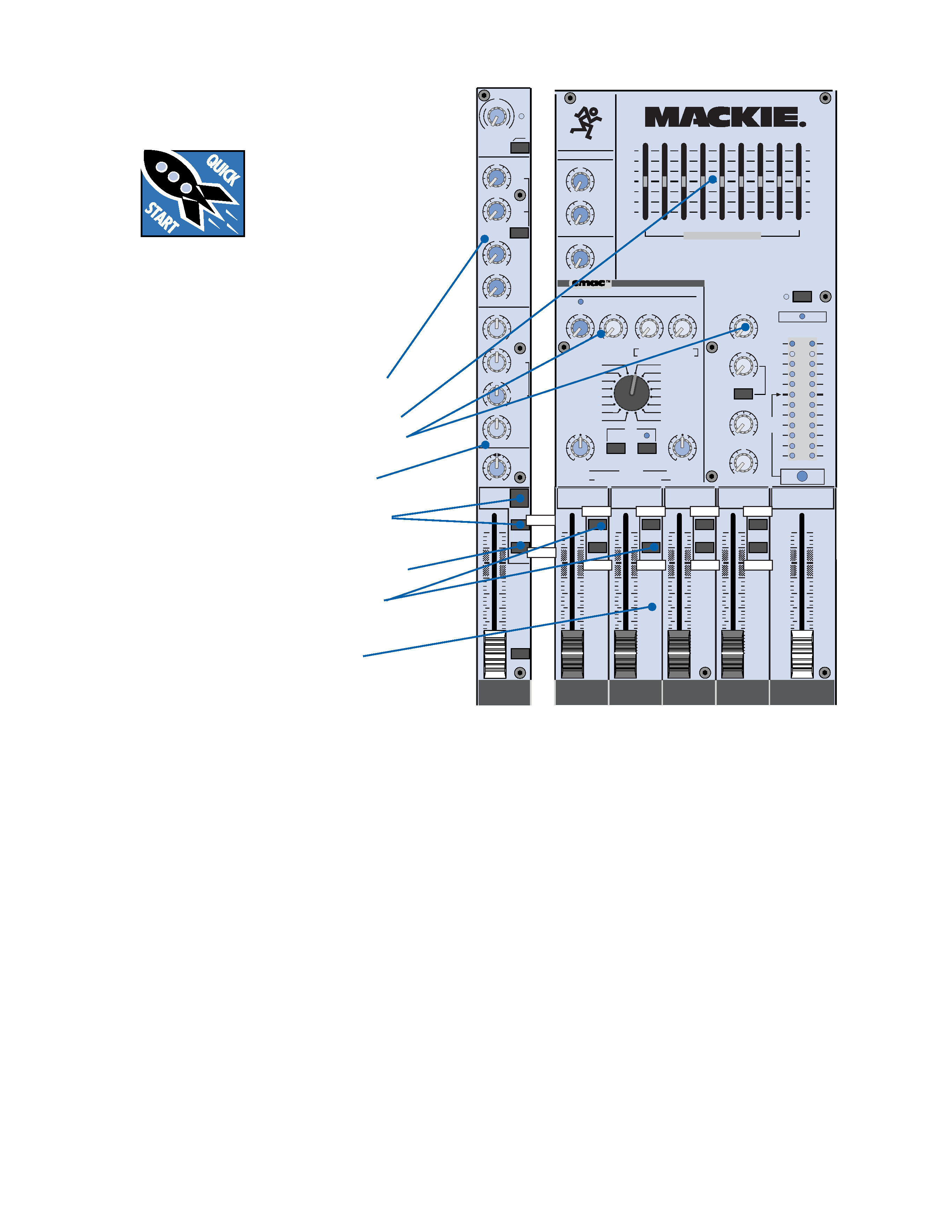
About those blue numbers:
You'll notice numbers in blue circles, like
this:
. Every feature on the CFX Mixer has
one of these numbers assigned to it. Whenever
a feature is mentioned, described or illustrated,
its number will be right next to it.
Thank you for choosing a Mackie Designs
CFXTM Mixer! These compact live-sound mixers
are designed to meet the sound reinforcement
needs of almost any small to medium-sized club,
meeting room, sanctuary, or outdoor gathering.
Here's a quick glance at all the features
you've acquired:
8, 12, or 16 mono channels, with:
·
Variable input trim
(+6 to +50 dB mic, 15 to +30 dB line)
·
Phantom power (globally switched)
·
Zero Level gain setting indicator LED
·
Switchable 100Hz low-cut filter
·
TRS insert jack
·
2 pre/post-fader aux sends
·
2 post-fader effects sends
·
3-band mid-sweep EQ
·
Pan, mute, and 1-2/3-4 busing
·
PFL solo
·
60mm mono fader
2 stereo line channels, with:
·
Variable input trim (20 to +20 dB)
·
2 pre/post-fader aux sends
·
2 post-fader effects sends
·
4-band EQ
·
Pan, mute, and 1-2/3-4 busing
·
PFL solo
·
60mm stereo fader
Please write your serial number here for
future reference (i.e., insurance claims, tech
support, return authorization, etc.):
Purchased at:
Date of purchase:
Part No. 820-104-00 Rev. A 5/99
©1999 Mackie Designs Inc. All Rights Reserved. Printed in the U.S.A.

4
Don't forget to visit our website at www.mackie.com
for more information about this and other Mackie products.
CONTENTS
MASTER SECTION FEATURES ................................ 15
MAIN MIX FADER ........................................ 15
METERS ...................................................... 15
RUDE SOLO ................................................. 15
STEREO GRAPHIC EQ .................................... 15
TAPE LEVEL ................................................. 16
BREAK SWITCH ........................................... 16
PHONES LEVEL ............................................ 16
UTILITY OUT LEVEL ...................................... 16
SUB FADERS ................................................ 16
LEFT/RIGHT SUB ASSIGN ............................. 16
AUX MASTER SEND ...................................... 17
EFX 1 MASTER SEND .................................... 17
EFX 1 RETURN ............................................ 17
EMAC EFFECTS PROCESSOR ........................... 17
EFX 2 SEND ................................................. 17
TO MAIN MIX ............................................. 17
EFFECTS TO MONITOR .................................. 18
PRESET SELECT ............................................ 18
TIME/RATE ................................................. 19
DAMPING/DEPTH ....................................... 19
WIDE ......................................................... 19
BYPASS ...................................................... 19
CLIP ........................................................... 19
GENERAL PRECAUTIONS AND CONSIDERATIONS .... 20
APPENDIX A: Service Info ................................... 20
Warranty Service ..................................... 20
Troubleshooting ........................................ 20
Repair..................................................... 21
APPENDIX B: Technical Info .................................. 21
Specifications ........................................... 21
Block Diagram .......................................... 22
Contributors and Colophon ......................... 23
CFX SERIES LIMITED WARRANTY ......................... 23
PRODUCT REGISTRATION CARD...............................
SAFETY INSTRUCTIONS .........................................2
INTRODUCTION ...................................................3
ABOUT THIS MANUAL ..........................................3
QUICK START ......................................................5
APPLICATIONS DIAGRAMS ....................................6
PATCHBAY FEATURES............................................8
MIC .............................................................8
LINE IN .........................................................8
INSERT .........................................................8
EFFECTS: SERIAL OR PARALLEL? ...................9
STEREO LINE IN .............................................9
MAIN OUT ....................................................9
SUBWOOFER OUT ..........................................9
MAIN INSERT ................................................9
UTILITY OUT ............................................... 10
SUB OUT .................................................... 10
AUX SEND .................................................. 10
EFX SEND ................................................... 10
STEREO EFX RETURN .................................... 10
TAPE INPUT ................................................ 11
TAPE OUTPUT .............................................. 11
PHONES ..................................................... 11
EFX FOOTSWITCH ........................................ 11
LAMP ......................................................... 11
AC POWER INPUT ........................................ 11
POWER SWITCH .......................................... 11
POWER STATUS ........................................... 11
CHANNEL STRIP FEATURES .................................. 12
PHANTOM POWER ...................................... 12
TRIM ......................................................... 12
ZERO LEVEL ................................................ 12
LOW CUT .................................................... 12
AUX ........................................................... 12
PRE FADER.................................................. 13
EFX 1 (EXT) ................................................. 13
EFX 2 (INT) ................................................. 13
EQ ............................................................. 13
PAN ........................................................... 14
MUTE ......................................................... 14
ASSIGN ...................................................... 14
FADER ........................................................ 14
SOLO PFL.................................................... 14
Attached to
back cover
5
SUB
1
RIGHT
LEFT
RIGHT
LEFT
RIGHT
LEFT
RIGHT
LEFT
dB
30
20
10
O
O
40
50
5
5
U
60
10
dB
30
20
10
O
O
40
50
5
5
U
60
10
dB
30
20
10
O
O
40
50
5
5
U
60
10
dB
30
20
10
O
O
40
50
5
5
U
60
10
dB
30
20
10
O
O
40
50
5
5
U
60
10
ASSIGN
SUB
2
ASSIGN
SUB
3
ASSIGN
SUB
4
ASSIGN
STEREO
MAIN MIX
DOWN
UP
DOWN
UP
UP
UP
UP
UP
1
3-4
1-2
MUTE
U
+15
O
O
U
+15
O
O
U
+15
O
O
U
+15
O
O
1
2
600
1.5k
150
8k
100
12k
HI
MID
FREQ
80Hz
LOW
EQ
U
+15
-15
U
+15
-15
U
+15
-15
ASSIGN
LR
PAN
dB
30
20
10
O
O
40
50
5
5
U
60
10
SOLO
PFL
1
EFX
2
(INT)
EFX
1
(EXT)
PRE FADER
AUX
TRIM
LOW CUT
100 Hz
ZERO
LEVEL
M
IC GAIN
6
+50
U
-15dB +30dB
DOWN
UP
CLIP
WIDE
BYPASS
10
0
10
0
REVERBS
DELAYS
CHORUS/FLANGE/PHASER
DAMPING
DEPTH
TIME
RATE
NORMAL
NORMAL
EFX
SM. ROOM
MD. PLATE
LG. PLATE
LG. HALL
GATED
REVERSE
CATHEDRAL
MD. HALL
SPRING
PHASER
DELAY 4
CHORUS
DELAY 3
DELAY 1
FLANGE
DELAY 2
CLIP
0dB=0dBu
LEFT RIGHT
ZERO
LEVEL
SET
TAPE LEVEL
O
O
MAX
PHONES LEVEL
UTILITY OUT LEVEL
48v
POWER
STATUS
RUDE
SOLO
BREAK SWITCH
(MUTES ALL CHANNELS)
U
+15
O
O
U
+15
O
O
U
+15
O
O
U
+15
O
O
U
+20
O
O
U
+20
O
O
U
+10
O
O
22
10
7
4
2
0
2
4
7
10
20
30
EFX
1 RETURN
EFX 2 (INT) RETURN MASTERS
EFX
2
SEND
TO MAIN MIX
EFFECTS TO MONITOR
AUX
1
AUX
2
PHANTOM POWER
CUSTOM 32-BIT PRECISION
DIGITAL STEREO EFFECTS PROCESSOR
1
(EXT)
15
15
5
10
0
5
10
15
15
5
10
0
5
10
U
+15
O
O
U
+15
O
O
U
+15
O
O
1
2
AUX
EFX
MASTER SEND
CFX 12 MIXER
STEREO GRAPHIC EQ
1K
500
250
63
125
16K
2K
4K
8K
12 CHANNEL COMPACT INTEGRATED LIVE SOUND MIXER
QUICK START
We know you can't wait to
get the show on the road.
Who has time to read a
booooring manual? That's
fine -- the CFX Mixer is
designed to set up quickly and operate intu-
itively -- but please, READ THIS PAGE!
ZERO THE CONSOLE:
1. Turn everything off, including the mixer's
POWER switch and PHANTOM POWER
switch.
2. Channel strip
TRIM, AUX, EFX, and
Fader down.
3.
STEREO GRAPHIC EQ sliders centered.
4.
MASTER AUX and EFX SENDS, and EFX
RETURNS down.
5. Channel strip
EQ and PAN controls
centered.
6. Channel strip
ASSIGN 1-2 and MUTE
switches
down.
7. Channel strip
LOW CUT, PRE FADER, and
ASSIGN 3-4 switches up.
8.
SUB 1 ASSIGN LEFT, SUB 2 ASSIGN
RIGHT down; all other SUB ASSIGN
switches up.
9.
MAIN MIX and SUB Faders down.
MAKE THE CONNECTIONS:
1. Connect your amp's outputs to your
speaker inputs (unless, of course, you have
powered monitors).
2. Plug all the sound system components into
suitable AC outlets, properly grounded and
capable of delivering adequate current.
3. Using XLR or TRS cables, make connec-
tions from your mixer's
MAIN OUT to your
amplification system's line inputs.
4. Make connections from your microphones
and instruments to the mixer: Connect
balanced microphones to the mono channel
MIC jacks. (For condenser microphones,
engage the
PHANTOM POWER switch,
located just above the meters.) Connect
line-level instruments (synthesizers, guitar
effects, direct boxes) to the mono or stereo
channel
LINE IN TRS jacks.
5. Turn all the power switches on, leaving the
amplifier's switch for last.
6. Turn up the
MAIN MIX Fader to the
"30" label, for now. We'll crank it up later on.
7. Turn up
SUB Faders 1 and 2 to unity gain
("
U" label).
SET THE LEVELS:
1. Choose one of the microphones or instru-
ments you connected. Make some noise. If
it's a microphone, sing at your normal
singing volume. If it's a synthesizer, play it
at its normal output level.
2. While making noise, turn up that channel's
TRIM until the adjacent ZERO LEVEL starts
blinking.
3. Disengage (up) that channel's
MUTE.
4. Raise that channel's fader to unity gain
("
U" label). You should be hearing your
noise now.
5. If necessary, apply channel
EQ changes.
(You may need to compensate for level
changes with the channel fader.)
6. Repeat steps 1 through 5 for the remaining
active channels.
7. Stop making noise. Everyone: start making
music.