
SR24·4-VLZ PRO &
SR32·4-VLZ PRO
OWNER'S MANUAL
2
CAUTION
AVIS
RISK OF ELECTRIC
SHOCK
DO NOT OPEN
RISQUE DE CHOC ELECTRIQUE
NE PAS OUVRIR
CAUTION: TO REDUCE THE RISK OF ELECTRIC SHOCK
DO NOT REMOVE COVER (OR BACK)
NO USER-SERVICEABLE PARTS INSIDE
REFER SERVICING TO QUALIFIED PERSONNEL
ATTENTION: POUR EVITER LES RISQUES DE CHOC
ELECTRIQUE, NE PAS ENLEVER LE COUVERCLE. AUCUN
ENTRETIEN DE PIECES INTERIEURES PAR L'USAGER. CONFIER
L'ENTRETIEN AU PERSONNEL QUALIFIE.
AVIS: POUR EVITER LES RISQUES D'INCENDIE OU
D'ELECTROCUTION, N'EXPOSEZ PAS CET ARTICLE
A LA PLUIE OU A L'HUMIDITE
The lightning flash with arrowhead symbol within an equilateral
triangle is intended to alert the user to the presence of uninsulated
"dangerous voltage" within the product's enclosure, that may be
of sufficient magnitude to constitute a risk of electric shock to persons.
Le symbole éclair avec point de flèche à l'intérieur d'un triangle
équilatéral est utilisé pour alerter l'utilisateur de la présence à
l'intérieur du coffret de "voltage dangereux" non isolé d'ampleur
suffisante pour constituer un risque d'éléctrocution.
The exclamation point within an equilateral triangle is intended to
alert the user of the presence of important operating and maintenance
(servicing) instructions in the literature accompanying the appliance.
Le point d'exclamation à l'intérieur d'un triangle équilatéral est
employé pour alerter les utilisateurs de la présence d'instructions
importantes pour le fonctionnement et l'entretien (service) dans le
livret d'instruction accompagnant l'appareil.
Duration Per Day
Sound Level dBA,
Typical
In Hours
Slow Response
Example
8
90
Duo in small club
692
4
95
Subway Train
397
2
100
Very loud classical music
1.5
102
1
105
Patrice screaming at Ron about deadlines
0.5
110
0.25 or less
115
Loudest parts at a rock concert
WARNING -- To reduce the risk of fire or electric shock,
do not expose this appliance to rain or moisture.
11. Damage Requiring Service -- This Mackie product should be serviced
only by qualified service personnel when:
A. The power-supply cord or the plug has been damaged; or
B. Objects have fallen, or liquid has spilled into this Mackie
product; or
C. This Mackie product has been exposed to rain; or
D. This Mackie product does not appear to operate normally or
exhibits a marked change in performance; or
E. This Mackie product has been dropped, or its chassis
damaged.
12. Servicing -- The user should not attempt to service this Mackie product
beyond those means described in this operating manual. All other servicing
should be referred to the Mackie Service Department.
13. To prevent electric shock, do not use this polarized plug with an
extension cord, receptacle or other outlet unless the blades can be fully
inserted to prevent blade exposure.
Pour préevenir les chocs électriques ne pas utiliser cette fiche polariseé avec
un prolongateur, un prise de courant ou une autre sortie de courant, sauf si les
lames peuvent être insérées à fond sans laisser aucune pariie à découvert.
14. Grounding or Polarization -- Precautions should be taken so that the
grounding or polarization means of this Mackie product is not defeated.
15. This apparatus does not exceed the Class A/Class B (whichever is
applicable) limits for radio noise emissions from digital apparatus as set out in the
radio interference regulations of the Canadian Department of Communications.
ATTENTION --Le présent appareil numérique n'émet pas de bruits
radioélectriques dépassant las limites applicables aux appareils numériques de
class A/de class B (selon le cas) prescrites dans le règlement sur le brouillage
radioélectrique édicté par les ministere des communications du Canada.
16. Exposure to extremely high noise levels may cause permanent hearing
loss. Individuals vary considerably in susceptibility to noise-induced hearing loss,
but nearly everyone will lose some hearing if exposed to sufficiently intense
noise for a period of time. The U.S. Government's Occupational Safety and
Health Administration (OSHA) has specified the permissible noise level exposures
shown in the following chart.
According to OSHA, any exposure in excess of these permissible limits
could result in some hearing loss. To ensure against potentially dangerous expo-
sure to high sound pressure levels, it is recommended that all persons exposed
to equipment capable of producing high sound pressure levels use hearing pro-
tectors while the equipment is in operation. Ear plugs or protectors in the ear
canals or over the ears must be worn when operating the equipment in order to
prevent a permanent hearing loss if exposure is in excess of the limits set forth
here.
SAFETY INSTRUCTIONS
1. Read Instructions -- All the safety and operation instructions should be
read before this Mackie product is operated.
2. Retain Instructions -- The safety and operating instructions should be kept
for future reference.
3. Heed Warnings -- All warnings on this Mackie product and in these operating
instructions should be followed.
4. Follow Instructions -- All operating and other instructions should be
followed.
5. Water and Moisture -- This Mackie product should not be used near water
for example, near a bathtub, washbowl, kitchen sink, laundry tub, in a wet
basement, near a swimming pool, swamp or salivating St. Bernard dog, etc.
6. Ventilation -- This Mackie product should be situated so that its
location or position does not interfere with its proper ventilation. For
example, the Component should not be situated on a bed, sofa, rug, or
similar surface that may block any ventilation openings, or placed in a
built-in installation such as a bookcase or cabinet that may impede the
flow of air through ventilation openings.
7. Heat -- This Mackie product should be situated away from heat sources
such as radiators, or other devices which produce heat.
8. Power Sources -- This Mackie product should be connected to a power
supply only of the type described in these operation instructions or as marked
on this Mackie product.
9. Power Cord Protection -- Power supply cords should be routed so that
they are not likely to be walked upon or pinched by items placed upon or
against them, paying particular attention to cords at plugs, convenience
receptacles, and the point where they exit this Mackie product.
10. Object and Liquid Entry -- Care should be taken so that objects do not
fall on, and liquids are not spilled into, this Mackie product.

3
INTRODUCTION
Thank you for choosing a Mackie Designs
professional sound reinforcement mixer! The
24·4-VLZ PRO and 32·4-VLZ PRO are
equipped with our new precision-engineered
XDRTM Extended Dynamic Range premium
studio-grade mic preamps, featuring:
· Full gain range from 0 to 60dB
· Massive +22dBu line signal handling
capability
· 130dB dynamic range
· Distortion and noise: 0.0007%, 20Hz to
20kHz
· Bullet-proof RF rejection using a
DC pulse transformer
· 192kHz bandwidth
These live sound mixers are designed to
meet the needs of almost any venue: indoor
concert, club or theatre, meeting room, sanctu-
ary, outdoor gathering, as well as a recording
studio.
Here's a quick glance at all the features
you've acquired:
20 mono channels (24·4-VLZ PRO) or
28 mono channels (32·4-VLZ PRO)
with:
· Mackie's cutting-edge XDRTM
microphone preamps
· Variable input trim (0 to +60dB mic, -15
to +45dB line)
· Phantom power (globally switched)
· Switchable 75Hz low cut filter
· TRS insert jack
· 2 pre-fader aux sends
· 2 switchable pre or post-fader aux sends
· 2 post-fader aux sends
· 3-band mid-sweep EQ
· Pan, mute, and 1-2/3-4/L-R bussing
· PFL or AFL solo
· 60mm mono fader
2 stereo line channels, with:
· -20dB to +20dB variable input trim
· 2 pre-fader aux sends
· 2 switchable pre or post-fader aux sends
· 2 post-fader aux sends
· 4-band EQ
· Pan, mute, and 1-2/3-4/L-R bussing
· PFL or AFL solo
· 60mm stereo fader
Comprehensive master section, with:
· 60mm subgroup mono faders
· Assign-to-main switching for each sub
group
· "Air" EQ for each subgroup
· PFL or AFL solo for each subgroup
· 60mm main mix stereo fader
· TRS insert jacks for main mix
· Balanced XLR and TRS stereo main outs
· XLR mono output with level control
· 13-segment stereo LED metering
· Mackie's (in)famous Rude Solo Light
· 6 aux send masters with level controls
· 4 stereo aux returns with level controls
· 2 effects to monitor controls
· RCA tape in & out
· Tape to Main Mix break switch
· XLR input for talkback microphone
· 2 headphone outputs with level control
· Control room output with level control
· 12V BNC lamp socket
At Mackie, we know what it takes to make
roadworthy gear. After all, our mixers have
traveled all over the world under the worst of
conditions. We've applied these experiences to
the mechanical design of the 24·4-VLZ PRO
and 32·4-VLZ PRO mixers.
Live sound only? No way! Although both
mixers are aimed primarily at sound reinforce-
ment, they have features such as 4-buss,
metering and control room circuitry, that make
them serve easily as recording or mixing con-
soles.
Part No. 820-213-00 Rev. A 03/2000
©2000 Mackie Designs Inc. All Rights Reserved. Printed in the U.S.A.
®
Please write your serial number here for
future reference (i.e., insurance claims, tech
support, return authorization, etc.):
Serial Number
Purchased at:
Date of purchase:
Make sure that you keep your proof of pur-
chase in a safe place, otherwise it will end up
in the land of enchantment, where TV remotes,
car keys and odd socks go.
4
ABOUT THIS MANUAL
The stuff you MUST read:
First, you must read and follow all the safety
instructions on page 2.
Before you get to work, please read the
"Quick Start" section on page 6. It's a list of
steps that will familiarize you with the mixer
and help you set up a basic performance. The
rest of the manual explains the mixer's fea-
tures in excruciating detail.
24·4-VLZ PRO and 32·4-VLZ PRO
This manual covers both mixers. The 32·4-
VLZ PRO has eight more mic/line channel
strips, otherwise the two models are identical.
About all those numbers:
Every feature on the mixer has a number as-
signed to it. Whenever a feature is illustrated
described or mentioned, its number will be
right next to it. They'll help you find your way
around this whopping opus, and we opus you
will like it.
Every feature of the mixer is described "geo-
graphically;" in other words, in order of where
it is physically placed on the mixer's top or rear
panel. These descriptions are divided into
three chapters, just as your mixer is organized
into three distinct zones:
PATCHBAY (page 14)
Along the back where everything plugs in.
CHANNEL STRIPS (page 19)
The mono mic/line channel strips and the
two stereo line channel strips.
MASTER SECTION (page 22)
The section on the right.
®
dB
30
20
10
O
O
40
50
5
5
U
60
10
dB
30
20
10
O
O
40
50
5
5
U
60
10
dB
30
20
10
O
O
40
50
5
5
U
60
10
dB
30
20
10
O
O
40
50
5
5
U
60
10
dB
30
20
10
O
O
40
50
5
5
U
60
10
dB
30
20
10
O
O
40
50
5
5
U
60
10
dB
30
20
10
O
O
40
50
5
5
U
60
10
dB
30
20
10
O
O
40
50
5
5
U
60
10
O
O
U
O
O
+15
U
O
O
+15
O
O
U
O
O
+15
MAX
MAX
U
O
O
+20
U
O
O
+20
U
O
O
+20
U
O
O
+20
U
O
O
+20
U
O
O
+15
U
O
O
+15
U
O
O
+15
U
O
O
+15
U
O
O
+15
U
O
O
+15
5
+10
0
5
+10
0
5
+10
0
5
+10
0
LR
LR
LR
LR
MI
C GAIN
10
U
60
+10dB -40dB
-10
LR
LR
LR
U
O
O
+15
U
O
O
+15
U
O
O
+15
U
O
O
+15
U
+15
-15
U
+15
-15
8kHz
100
U
+15
-15
U
O
O
+15
U
O
O
+15
U
+15
-15
U
+15
-15
U
+15
-15
U
+15
-15
U
+15
-15
U
+15
-15
U
+15
-15
U
+15
-15
U
O
O
+15
U
O
O
+15
U
O
O
+15
U
O
O
+15
U
O
O
+15
U
O
O
+15
U
O
O
+15
U
O
O
+15
U
O
O
+15
U
O
O
+15
U
O
O
+15
U
O
O
+15
-20
+20
U
-20
+20
U
16kHz
16kHz
16kHz
16kHz
LAMP
STEREO
AUX RETURNS
AUX SEND
MASTERS
LEVEL
5
6
AIR
AIR
AIR
AIR
SOLO
SOLO
SOLO
SOLO
1
2
3
4
1
2
1
2
3
4
SOLO
SOLO
1-2
SUB
SOLO
GLOBAL
AUX RETURN
ASSIGN
TO SUB
SOLO
SOLO
TAPE RETURN
TO PHONES / C R
TAPE RETURN
TO MAIN MIX
LEFT/RIGHT
MAIN MIX
AUX 1-2
TALKBACK
LEVEL
TAPE
RETURN
3-4
LEFT
RIGHT
L/R ASSIGN
L/R ASSIGN
L/R ASSIGN
L/R ASSIGN
SUB
SUB
SUB
SUB
12
3
4
PHONES / C-R
LEVEL
MAIN MIX
SOLO
TO AUX
SEND
1-2
(EFX TO MONITOR)
SOLO
28
CLIP
10
7
4
2
2
0
4
7
10
20
30
40
TRACK
1
·
5
TRACK
2
·
6
TRACK
3
·
7
TRACK
4
·
8
SOLO
MODE
SUB
AUX
PRE FADER
IN PLACE AFL
LEVEL SET
PAN
PAN
PAN
PAN
POWER
RUDE
SOLO
LIGHT
OPERATING LEVEL
0dB = 0dBu
12k
HI
3k
MID
HI
800Hz
MID
LOW
EQ
12k
HI
3k
MID
HI
800Hz
MID
LOW
EQ
-20
OL
PRE
1
PRE
PRE
2
3
5
6
12k
HI
MID
FREQ
80Hz
LOW CUT
75 Hz
18dB/OCT
LOW
80Hz
LOW
80Hz
LOW
TRIM
1
AUX
1
MUTE
EQ
3-4
L-R
1-2
3-4
L-R
1-2
3-4
L-R
1-2
-20
OL
-20
OL
TRIM
21
22
TRIM
23
24
PRE
1
PRE
PRE
2
3
5
6
AUX
PRE
1
PRE
PRE
2
3
5
6
AUX
21 22
MUTE
23 24
MUTE
SOLO
SOLO
SOLO
MUTE / SOLO
MUTE / SOLO
MUTE / SOLO
PAN
PAN
PAN
4
44
LINE ONLY CHANNELS 21-24
MIC/LINE CHANNELS 1-20 (IDENTICAL)
MASTER SECTION
PATCHBAY
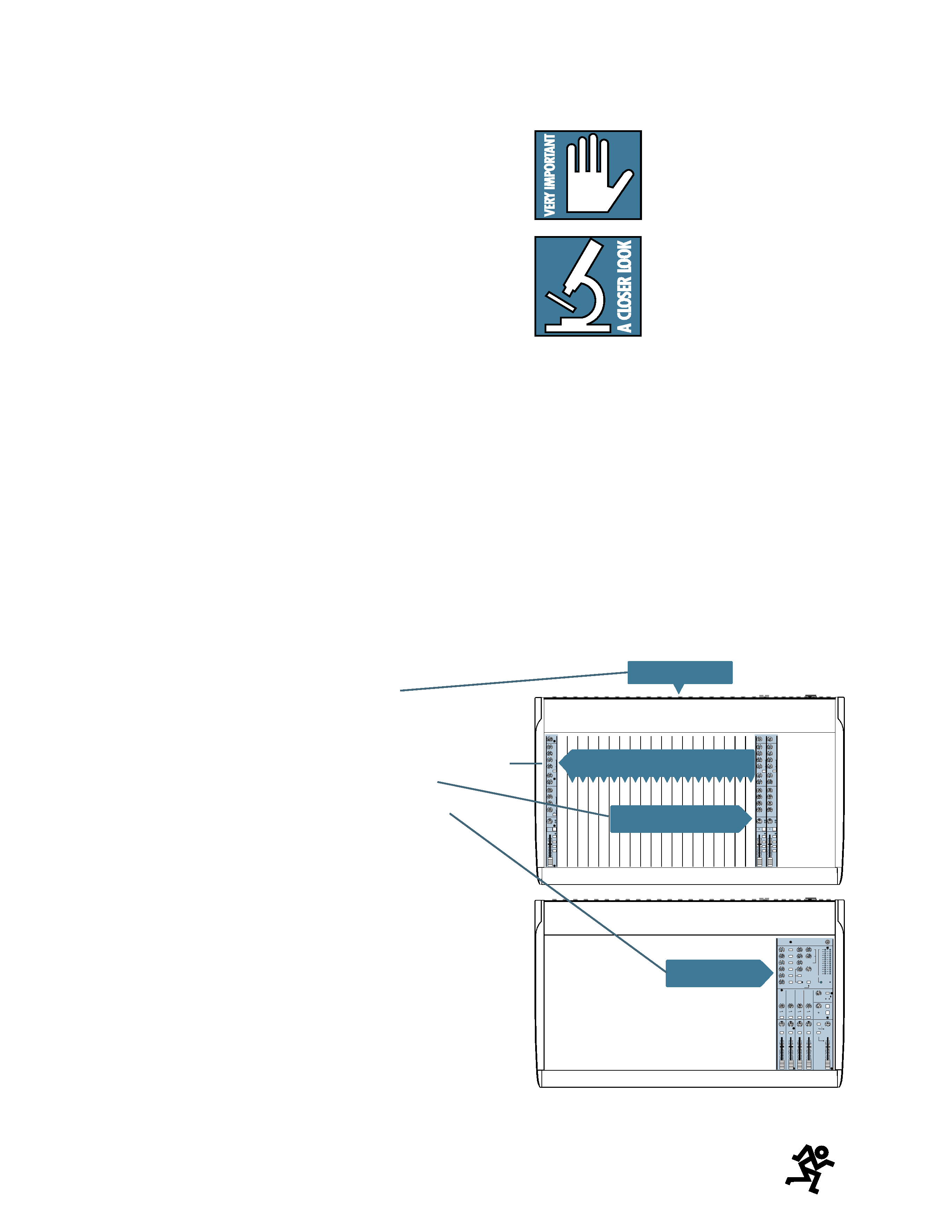
Further information:
This icon marks infor-
mation that is critically
important or unique to your
mixer. For your own good,
read and remember them.
This icon will lead you
to in-depth explanations of
features and practical tips.
While not mandatory, they
usually have some valuable
nuggets of information.
This entire manual is condensed onto one
page, albeit in hieroglyphics: see the Block Dia-
gram on page 28.
Please come on by and visit our website, at
http://www.mackie.com. It contains helpful
stuff about mixers and audio, as well as spe-
cific information about this and other Mackie
products.

5
CONTENTS
SAFETY INSTRUCTIONS ............................... 2
INTRODUCTION ......................................... 3
ABOUT THIS MANUAL ................................ 4
QUICK START ............................................ 6
APPLICATIONS DIAGRAMS .......................... 9
PATCHBAY FEATURES
MIC .................................................. 14
LINE IN .............................................. 14
INSERT ............................................... 15
EFFECTS: SERIAL OR PARALLEL? ............ 15
STEREO LINE IN ................................... 15
TAPE OUT ........................................... 16
TAPE IN .............................................. 16
SUB INSERTS ...................................... 16
SUB OUTS .......................................... 16
DOUBLE BUSSING ................................ 16
STEREO AUX RETURNS ......................... 17
AUX SENDS ........................................ 17
CONTROL ROOM OUT .......................... 17
MAIN OUTS (TRS) ............................... 17
MAIN INSERTS .................................... 17
MONO MAIN OUT ............................... 17
OUTPUT LEVEL .................................... 17
MAIN OUT (XLR) ................................. 17
TALKBACK MIC .................................... 17
PHONES ............................................. 18
PHANTOM SWITCH ............................. 18
POWER SWITCH .................................. 18
AC RECEPTACLE ................................... 18
FUSE .................................................. 18
CHANNEL STRIP FEATURES
TRIM ................................................. 19
AUX SEND
AUX ............................................ 19
PRE ............................................. 19
EQ SECTION
HI ............................................... 20
MID ............................................ 20
FREQ ........................................... 20
HI MID ........................................ 20
LOW MID ..................................... 20
LOW ........................................... 20
LOW CUT ..................................... 20
OL LED ............................................... 21
-20 LED .............................................. 21
PAN .................................................. 21
MUTE ................................................. 21
SOLO ................................................. 21
1-2 & 3-4........................................... 21
L-R .................................................. 21
CHANNEL FADER ................................. 21
MASTER SECTION FEATURES
LAMP CONNECTOR .............................. 22
AUX SEND MASTER
AUX SEND MASTERS ..................... 22
SOLO ........................................... 22
STEREO AUX RETURNS
STEREO AUX RETURNS .................. 23
TO AUX SEND 1-2 ......................... 23
ASSIGN TO SUB ............................ 23
SUB ............................................. 23
SOLO ........................................... 23
TAPE RETURN ..................................... 23
METERS ............................................. 23
ZERO EQUALS ZERO ............................ 23
POWER LED ........................................ 23
SUBGROUPS
AIR ............................................. 24
SOLO ........................................... 24
PAN ............................................ 24
L/R ASSIGN ................................. 24
SUBGROUP FADERS ...................... 25
SOLO
RUDE SOLO LIGHT ......................... 25
LEVEL .......................................... 25
MODE .......................................... 25
AUX LED ...................................... 25
SUB LED ....................................... 25
TALKBACK
LEVEL .......................................... 25
MAIN MIX ................................... 26
AUX 1-2 ...................................... 25
TAPE RETURN TO PHONES/C-R ............. 25
PHONES/C-R LEVEL ............................. 26
TAPE RETURN TO MAIN MIX ................. 26
MAIN MIX FADER ................................ 26
SPECIFICATIONS ........................................ 27
BLOCK DIAGRAM ....................................... 28
GAIN PATH ............................................... 29
SERVICE INFORMATION .............................. 30
page
page