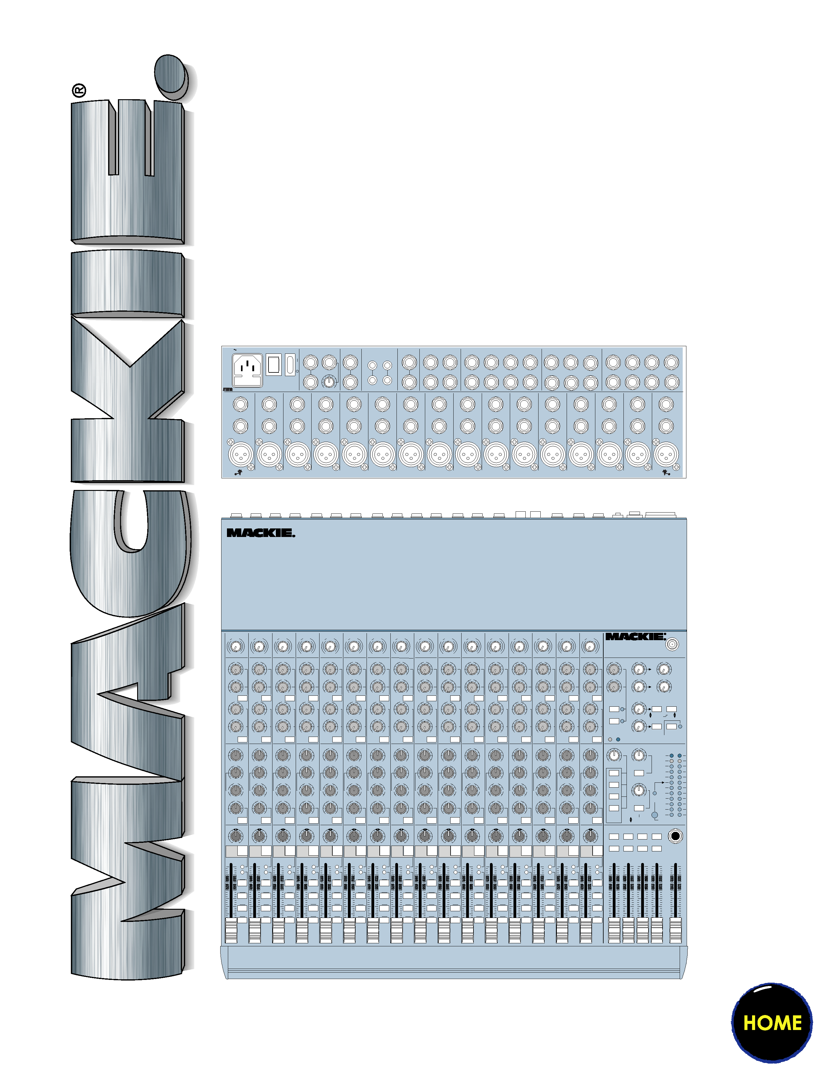
1604-VLZ PRO
16-CHANNEL
MIC/LINE MIXER
OWNER'S MANUAL
16
15
14
13
12
11
10
9
8
7
6
5
4
3
2
1
PAN
AUX
3
1
2
1
2
1
2
1
2
1
2
1
2
1
2
1
2
1
2
1
2
1
2
1
2
1
2
1
2
1
2
1
2
EQ
5
4
6
5/6
SHIFT
PRE
PRE
PRE
PRE
PRE
PRE
PRE
PRE
PRE
PRE
PRE
PRE
PRE
PRE
PRE
PRE
TRIM
12
3
4
5
6
7
8
9
10
11
12
13
14
15
16
SOLO
L - R
34
12
SOLO
L - R
34
12
SOLO
L - R
34
12
SOLO
L - R
34
12
SOLO
L - R
34
12
SOLO
L - R
34
12
SOLO
L - R
34
12
SOLO
L - R
34
12
SOLO
L - R
34
12
SOLO
L - R
34
12
SOLO
L - R
34
12
SOLO
L - R
34
12
SOLO
L - R
34
12
SOLO
L - R
34
12
SOLO
L - R
34
12
SOLO
L - R
34
12
OL
-20
OL
-20
OL
-20
OL
-20
OL
-20
OL
-20
OL
-20
OL
-20
OL
-20
OL
-20
OL
-20
OL
-20
OL
-20
OL
-20
OL
-20
OL
-20
PAN
AUX
3
EQ
5
4
6
5/6
SHIFT
PAN
AUX
3
EQ
5
4
6
5/6
SHIFT
PAN
AUX
3
EQ
5
4
6
5/6
SHIFT
PAN
AUX
3
EQ
5
4
6
5/6
SHIFT
PAN
AUX
3
EQ
5
4
6
5/6
SHIFT
PAN
AUX
3
EQ
5
4
6
5/6
SHIFT
PAN
AUX
3
EQ
5
4
6
5/6
SHIFT
PAN
AUX
3
EQ
5
4
6
5/6
SHIFT
PAN
AUX
3
EQ
5
4
6
5/6
SHIFT
PAN
AUX
3
EQ
5
4
6
5/6
SHIFT
PAN
AUX
3
EQ
EQ
5
4
6
5/6
SHIFT
PAN
AUX
3
5
4
6
5/6
SHIFT
PAN
AUX
3
EQ
5
4
6
5/6
SHIFT
PAN
AUX
3
EQ
5
4
6
5/6
SHIFT
PAN
AUX
3
EQ
5
4
6
5/6
SHIFT
TRIM
TRIM
TRIM
TRIM
TRIM
TRIM
TRIM
TRIM
TRIM
TRIM
TRIM
TRIM
TRIM
TRIM
TRIM
TRACK
8
TRACK
7
TRACK
6
TRACK
5
TRACK
4
TRACK
3
TRACK
2
TRACK
1
U
O
O
+15
U
O
O
+15
U
O
O
+15
U
+15
-15
U
+15
-15
800
2k
200
8k
U
+15
-15
12k
HI
MID
80Hz
LOW CUT
75 Hz
18dB/OCT
LOW
100
+15
-15
800
2k
200
8k
100
+15
-15
800
2k
200
8k
100
+15
-15
800
2k
200
8k
100
+15
-15
800
2k
200
8k
100
+15
-15
800
2k
200
8k
100
+15
-15
800
2k
200
8k
100
+15
-15
800
2k
200
8k
100
+15
-15
800
2k
200
8k
100
+15
-15
800
2k
200
8k
100
+15
-15
800
2k
200
8k
100
+15
-15
800
2k
200
8k
100
+15
-15
800
2k
200
8k
100
+15
-15
800
2k
200
8k
100
+15
-15
800
2k
200
8k
100
+15
-15
800
2k
200
8k
100
U
O
O
+15
U
O
O
+15
U
O
O
+15
U
O
O
+15
U
O
O
+15
U
O
O
+15
U
O
O
+15
U
O
O
+15
U
O
O
+15
U
O
O
+15
U
O
O
+15
U
O
O
+15
U
O
O
+15
U
O
O
+15
U
O
O
+15
U
O
O
+15
U
O
O
+15
U
O
O
+15
U
O
O
+15
U
O
O
+15
U
O
O
+15
U
O
O
+15
U
O
O
+15
U
O
O
+15
U
O
O
+15
U
O
O
+15
U
O
O
+15
U
O
O
+15
U
O
O
+15
U
O
O
+15
U
O
O
+15
1
MUTE
U
O
O
+15
U
+15
-15
U
U
+15
-15
12k
HI
MID
80Hz
LOW CUT
75 Hz
18dB/OCT
LOW
U
O
O
+15
2
MUTE
U
O
O
+15
U
+15
-15
U
U
+15
-15
12k
HI
MID
80Hz
LOW CUT
75 Hz
18dB/OCT
LOW
U
O
O
+15
3
MUTE
U
O
O
+15
U
+15
-15
U
U
+15
-15
12k
HI
MID
80Hz
LOW CUT
75 Hz
18dB/OCT
LOW
U
O
O
+15
4
MUTE
U
O
O
+15
U
+15
-15
U
U
+15
-15
12k
HI
MID
80Hz
LOW CUT
75 Hz
18dB/OCT
LOW
U
O
O
+15
5
MUTE
U
O
O
+15
U
+15
-15
U
U
+15
-15
12k
HI
MID
80Hz
LOW CUT
75 Hz
18dB/OCT
LOW
U
O
O
+15
6
MUTE
U
O
O
+15
U
+15
-15
U
U
+15
-15
12k
HI
MID
80Hz
LOW CUT
75 Hz
18dB/OCT
LOW
U
O
O
+15
7
MUTE
U
O
O
+15
U
+15
-15
U
U
+15
-15
12k
HI
MID
80Hz
LOW CUT
75 Hz
18dB/OCT
LOW
U
O
O
+15
8
MUTE
U
O
O
+15
U
+15
-15
U
U
+15
-15
12k
HI
MID
80Hz
LOW CUT
75 Hz
18dB/OCT
LOW
U
O
O
+15
9
MUTE
U
O
O
+15
U
+15
-15
U
U
+15
-15
12k
HI
MID
80Hz
LOW CUT
75 Hz
18dB/OCT
LOW
U
O
O
+15
10
MUTE
U
O
O
+15
U
+15
-15
U
U
+15
-15
12k
HI
MID
80Hz
LOW CUT
75 Hz
18dB/OCT
LOW
U
O
O
+15
11
MUTE
U
O
O
+15
U
+15
-15
U
U
+15
-15
12k
HI
MID
80Hz
LOW CUT
75 Hz
18dB/OCT
LOW
U
O
O
+15
12
MUTE
U
O
O
+15
U
+15
-15
U
U
+15
-15
12k
HI
MID
MID
MID
MID
80Hz
LOW CUT
75 Hz
18dB/OCT
LOW
U
O
O
+15
13
MUTE
U
O
O
+15
U
+15
-15
U
U
+15
-15
12k
HI
80Hz
LOW CUT
75 Hz
18dB/OCT
LOW
U
O
O
+15
14
MUTE
U
O
O
+15
U
+15
-15
U
U
+15
-15
12k
HI
80Hz
LOW CUT
75 Hz
18dB/OCT
LOW
U
O
O
+15
15
MUTE
U
O
O
+15
U
+15
-15
U
U
+15
-15
12k
HI
80Hz
LOW CUT
75 Hz
18dB/OCT
LOW
U
O
O
+15
16
MUTE
MIC
GAIN
060
+15dB -45dB
-10dBV
MIC
GAIN
060
+15dB -45dB
-10dBV
MIC
GAIN
060
+15dB -45dB
-10dBV
MIC
GAIN
060
+15dB -45dB
-10dBV
MIC
GAIN
060
+15dB -45dB
-10dBV
MIC
GAIN
060
+15dB -45dB
-10dBV
MIC
GAIN
060
+15dB -45dB
-10dBV
MIC
GAIN
060
+15dB -45dB
-10dBV
MIC
GAIN
060
+15dB -45dB
-10dBV
MIC
GAIN
060
+15dB -45dB
-10dBV
MIC
GAIN
060
+15dB -45dB
-10dBV
MIC
GAIN
060
+15dB -45dB
-10dBV
MIC
GAIN
060
+15dB -45dB
-10dBV
MIC
GAIN
060
+15dB -45dB
-10dBV
MIC
GAIN
060
+15dB -45dB
-10dBV
MIC
GAIN
060
+15dB -45dB
-10dBV
U
U
U
U
U
U
U
U
U
U
U
U
U
U
U
U
LR
LR
LR
LR
LR
LR
LR
LR
LR
LR
LR
LR
LR
LR
LR
LR
O
O
O
O
O
O
O
O
O
O
O
O
O
O
O
O
O
O
O
O
O
O
O
O
O
O
O
O
O
O
O
O
AUX
SEND
STEREO AUX RETURN
EFFECTS TO
MONITORS
TO AUX
SEND 2
TO AUX
SEND 1
1
2
PWR
PHAN
SOLO
SOLO
1
2
1
2
3
4
1
2
C-R / PHNS
ONLY
RETURNS
SOLO
MAIN MIX
TO SUBS
ASSIGN OPTIONS
12
34
U
O
O
+20
U
O
O
+20
U
O
O
+15
U
O
O
+15
U
O
O
+20
U
O
O
+20
U
O
O
+10
U
O
O
+10
LEFT RIGHT
PHONES
LAMP
12V
0.5A
TAPE IN
SOLO
RUDE
SOLO
LIGHT
CTL ROOM / PHONES
SUBS 34
SUBS 12
MAIN MIX
CTL ROOM
SOURCE
TAPE
TAPE TO
MAIN MIX
MAIN
MIX
RIGHT
1234
LEFT
RIGHT
LEFT
RIGHT
LEFT
RIGHT
LEFT
28
10
7
4
2
2
0
4
7
10
20
30
ASSIGN TO MAIN MIX
LEVEL
SET
MODE
(AFL)
LEVEL SET
NORMAL
(PFL)
U
O
O
+20
O
O
O
O
MAX
0 dB=0 dBu
MAX
dB
30
20
10
O
O
40
50
5
5
U
60
10
dB
30
20
10
O
O
40
50
5
5
U
60
10
1604-VLZ PRO
16-CHANNEL MIC/ LINE MIXER
WITH PREMIUM XDRTM MIC PREAMPLIFIERS
1604-VLZ PRO
16-CHANNEL MIC/ LINE MIXER
WITH PREMIUM XDRTM MIC PREAMPLIFIERS
UTILISE UN FUSIBLE DE RECHANGE DE MÊME TYPE. DEBRANCHER AVANT DE REMPLACER LE FUSIBLE
43
21
INSERT
INSERT
INSERT
LINE
INSERT
MIC 4
MIC 3
MIC 2
MIC 1
BAL
UN-
BAL
BAL
UN-
BAL
BAL
UN-
BAL
BAL
UN-
BAL
LINE
LINE
LINE
O
O
+6
PHANTOM
ON
POWER
ON
120 VAC 50/60 Hz 20W
1A/250V SLO-BLO
16
15
14
13
12
11
10
9
8
7
6
5
MIC 16
INSERT
INSERT
INSERT
INSERT
INSERT
INSERT
INSERT
INSERT
INSERT
INSERT
INSERT
INSERT
MIC 15
MIC 14
MIC 13
MIC 12
MIC 11
MIC 10
MIC 9
MIC 8
MIC 7
MIC 6
MIC 5
SUB OUT
C-R OUT
MAIN INSERT
(TIP SEND
RING RETURN)
TAPE
TAPE
MAIN OUT
AUX SEND
DIRECT OUT
AUX RETURN
3
R
L
MONO
R
R
R
R
L
R
L
R
L
R
L
LL
L
1
42
5
1
2
3
4
31
642
753
864
1
2
BAL/UNBAL
BAL/UNBAL
BAL/UNBAL
BAL/UNBAL
BAL/UNBAL
BAL/UNBAL
INPUT
OUTPUT
R
L
(MONO)
(MONO)
(MONO)
BAL
UN-
BAL
BAL
UN-
BAL
BAL
UN-
BAL
BAL
UN-
BAL
BAL
UN-
BAL
BAL
UN-
BAL
BAL
UN-
BAL
BAL
UN-
BAL
BAL
UN-
BAL
BAL
UN-
BAL
BAL
UN-
BAL
BAL
UN-
BAL
LINE
LINE
LINE
LINE
LINE
LINE
LINE
LINE
LINE
LINE
LINE
LINE
TO REDUCE THE RISK OF
FIRE REPLACE WITH SAME
TYPE FUSE AND RATING
CAUTION:
UTILISE UN FUSIBLE DE RECHANGE DE MÊME TYPE. DEBRANCHER AVANT DE REMPLACER LE FUSIBLE
CONCEIVED, DESIGNED, AND MANUFACTURED BY MACKIE DESIGNS INC · WOODINVILLE · WA · USA · MADE IN USA · FABRIQUE AU USA · COPYRIGHT ©1998 · THE FOLLOWING ARE TRADEMARKS OR REGISTERED TRADEMARKS OF MACKIE DESIGN INC.: "MACKIE", "VLZ", "XDR", AND THE "RUNNING MAN" FIGURE · US PATENT NUMBER 29/049,129
XDRTM EXTENDED DYNAMIC RANGE MIC PREAMPLIFIERS ARE PROPRIETARY TO MACKIE DESIGNS, INC.
XDR
MIC PRE
XDR
MIC PRE
XDR
MIC PRE
XDR
MIC PRE
XDR
MIC PRE
XDR
MIC PRE
XDR
MIC PRE
XDR
MIC PRE
XDR
MIC PRE
XDR
MIC PRE
XDR
MIC PRE
XDR
MIC PRE
XDR
MIC PRE
XDR
MIC PRE
XDR
MIC PRE
XDR
MIC PRE
CAUTION
AVIS
RISK OF ELECTRIC
SHOCK
DO NOT OPEN
RISQUE DE CHOC ELECTRIQUE
NE PAS OUVRIR
CAUTION: TO REDUCE THE RISK OF ELECTRIC SHOCK
DO NOT REMOVE COVER (OR BACK)
NO USER-SERVICEABLE PARTS INSIDE
REFER SERVICING TO QUALIFIED PERSONNEL
ATTENTION: POUR EVITER LES RISQUES DE CHOC
ELECTRIQUE, NE PAS ENLEVER LE COUVERCLE. AUCUN
ENTRETIEN DE PIECES INTERIEURES PAR L'USAGER. CONFIER
L'ENTRETIEN AU PERSONNEL QUALIFIE.
AVIS: POUR EVITER LES RISQUES D'INCENDIE OU
D'ELECTROCUTION, N'EXPOSEZ PAS CET ARTICLE
A LA PLUIE OU A L'HUMIDITE
The lightning flash with arrowhead symbol within an equilateral
triangle is intended to alert the user to the presence of uninsulated
"dangerous voltage" within the product's enclosure, that may be
of sufficient magnitude to constitute a risk of electric shock to persons.
Le symbole éclair avec point de flèche à l'intérieur d'un triangle
équilatéral est utilisé pour alerter l'utilisateur de la présence à
l'intérieur du coffret de "voltage dangereux" non isolé d'ampleur
suffisante pour constituer un risque d'éléctrocution.
The exclamation point within an equilateral triangle is intended to
alert the user of the presence of important operating and maintenance
(servicing) instructions in the literature accompanying the appliance.
Le point d'exclamation à l'intérieur d'un triangle équilatéral est
employé pour alerter les utilisateurs de la présence d'instructions
importantes pour le fonctionnement et l'entretien (service) dans le
livret d'instruction accompagnant l'appareil.
SAFETY INSTRUCTIONS
1. Read Instructions -- All the safety and operation
instructions should be read before this Mackie product is
operated.
2. Retain Instructions -- The safety and operating instruc-
tions should be kept for future reference.
3. Heed Warnings -- All warnings on this Mackie product and
in these operating instructions should be followed.
4. Follow Instructions -- All operating and other instructions
should be followed.
5. Water and Moisture -- This Mackie product should not be
used near water for example, near a bathtub, washbowl,
kitchen sink, laundry tub, in a wet basement, near a
swimming pool, swamp or salivating St. Bernard dog, etc.
6. Heat -- This Mackie product should be situated away
from heat sources such as radiators, or other devices which
produce heat.
7. Power Sources -- This Mackie product should be
connected to a power supply only of the type described in
these operation instructions or as marked on this Mackie
product.
8. Power Cord Protection -- Power supply cords should be
routed so that they are not likely to be walked upon or
pinched by items placed upon or against them, paying
particular attention to cords at plugs, convenience receptacles,
and the point where they exit this Mackie product.
9. Object and Liquid Entry -- Care should be taken so that
objects do not fall into and liquids are not spilled into the
inside of this Mackie product.
10. Damage Requiring Service -- This Mackie product should
be serviced only by qualified service personnel when:
A. The power-supply cord or the plug has been
damaged; or
B. Objects have fallen, or liquid has spilled into
this Mackie product; or
C. This Mackie product has been exposed to rain;
or
D. This Mackie product does not appear to operate
normally or exhibits a marked change in
performance; or
E. This Mackie product has been dropped, or its
chassis damaged.
11. Servicing -- The user should not attempt to service this
Mackie product beyond those means described in this
operating manual. All other servicing should be referred to the
Mackie Service Department.
12. To prevent electric shock, do not use this polarized plug
with an extension cord, receptacle or other outlet unless the
blades can be fully inserted to prevent blade exposure.
Pour préevenir les chocs électriques ne pas utiliser cette fiche
polariseé avec un prolongateur, un prise de courant ou une
autre sortie de courant, sauf si les lames peuvent être insérées
à fond sans laisser aucune pariie à découvert.
13. Grounding or Polarization -- Precautions should be taken
so that the grounding or polarization means of this Mackie
product is not defeated.
14. This apparatus does not exceed the Class A/Class B
(whichever is applicable) limits for radio noise emissions from
digital apparatus as set out in the radio interference
regulations of the Canadian Department of Communications.
ATTENTION --Le présent appareil numérique n'émet pas de
bruits radioélectriques dépassant las limites applicables aux
appareils numériques de class A/de class B (selon le cas)
prescrites dans le règlement sur le brouillage radioélectrique
édicté par les ministere des communications du Canada.
15. To prevent hazard or damage, ensure that only
microphone cables and microphones designed to IEC 268-15A
are connected.
WARNING -- To reduce the risk of fire or electric shock, do
not expose this appliance to rain or moisture.

Errata
Please update the SPECIFICATIONS section of your owner's manual with the following:
· All three models in the VLZ PRO Series produce less than 0.0007% THD
(Total Harmonic Distortion, 20Hz-20kHz).
· The 1604-VLZ PRO joins the other two models in providing better than 90 dB CMR
(Common Mode Rejection, Mic In to Insert Send Out, maximum gain at 1kHz).
VLZ PRO SERIES
Mackie Designs Inc. · 16220 Wood-Red Road N.E.
Woodinville · WA · 98072 · 800/258-6883 · www.mackie.com
Outside the U.S. call 425/487-4333 · FAX 425/487-4337
© 1999 Mackie Designs Inc. All rights reserved.
Printed in the USA.
Part No. 820-034-02 Rev. A 4/99
Since this manual was produced, we
have improved the performance of
the VLZ PRO SERIES mixers.
3
We realize that you must have a powerful
hankerin' to try out your new 1604-VLZ PRO. Or
you might be one of those people who never
reads manuals. Either way, all we ask is that
you read this page NOW, and the rest can wait
until you're good and ready. But do read it --
you'll be glad you did.
Other Nuggets of Wisdom
For optimum sonic performance, the channel
faders and the
MAIN MIX fader should be set near
the "
U" (unity gain) markings.
Always turn the
MAIN MIX fader and CTL
ROOM/PHONES knob down before making con-
nections to and from your 1604-VLZPRO.
If you shut down your equipment, turn off your
amplifiers first. When powering up, turn on your
amplifiers last.
Save the shipping box! You may need it
someday, and you don't want to have to pay for
another one.
INSTANT MIXING
Here's how to get going
right away, assuming you own a
microphoneandakeyboard:
1. Plug your microphone into Channel 1's
MIC
input.
2. Turn on the 1604-VLZPRO.
3. Perform the Level-Setting Procedure
.
4. Connect cords from the
MAIN OUT jacks to
your amplifier.
5. Hook up speakers to the amp and turn it on.
6. Set channel 1's fader to the "
U" mark.
7. Engage (push in) Channel 1's
L-R switch.
8. Set the
MAIN MIX fader one-quarter of the
way up.
9. Sing like a canary!
10. Plug your keyboard into channels 3 and 4.
11. Turn channel 3's
PAN knob fully left and
channel 4's
PAN knob fully right.
12. Set those faders to the "
U" mark.
13. Perform the Level-Setting Procedure
.
14. Engage the
L-R switch on these channels.
15. Play like a madman and sing like a canary!
It's your first mix!
READ THIS PAGE!!!
Please write your serial number here for
future reference (i.e. insurance claims, tech
support, return authorization, etc.):
Part No. 820-034-01 Rev. A 01/99
©1999 Mackie Designs, All Rights Reserved.
Printed in the U.S.A.
LEVEL-SETTING PROCEDURE
Message to seasoned pros:
do NOT set levels
using the old "Turn the trim up until the clip
light comes on, then back off a hair" trick. When a
Mackie Designs mixer clip light comes on, you
really are about to clip.
This procedure really works -- it assures
low noise and high headroom. Please read on.
It's not even necessary to hear what you're do-
ing to set optimal levels. But if you'd like to: Plug
headphones into the
PHONES output jack,
then set the
C-R PHONES knob about one-
quarter of the way up.
The following steps must be performed
one
channel at a time:
1. Turn the
TRIM, AUX send and fader
controls fully down.
2. Be sure the
12, 34 and LR channel
assignment switches are all disengaged.
3. Set the
EQ knobs at the center detents.
4. Connect the signal source to the
MIC or
LINE channel input.
5. Engage (push in) the channel's
SOLO
switch.
6. Push in the
MODE switch in the output
section (
LEVEL SET (PFL) mode) -- the
LEVEL SET LED will light.
7. Play something into the selected input, at
real-world levels.
8. Adjust the
TRIM control so that the
display on the meter stays around "0."
(Only the left meter is active in the
Level-Setting Procedure.)
9. If you'd like to apply some
EQ, do so
now and return to the previous step.
10. Disengage that channel's
SOLO switch.
11. Repeat for each of channels 116.
Purchased at:
Date of purchase:

4
PAN
AUX
3
1
2
1
2
1
2
1
2
1
2
1
2
1
2
1
2
1
2
1
2
1
2
1
2
1
2
1
2
1
2
1
2
EQ
5
4
6
5/6
SHIFT
PRE
PRE
PRE
PRE
PRE
PRE
PRE
PRE
PRE
PRE
PRE
PRE
PRE
PRE
PRE
PRE
TRIM
12
3
4
5
6
7
8
9
10
11
12
13
14
15
16
SOLO
L - R
34
12
SOLO
L - R
34
12
SOLO
L - R
34
12
SOLO
L - R
34
12
SOLO
L - R
34
12
SOLO
L - R
34
12
SOLO
L - R
34
12
SOLO
L - R
34
12
SOLO
L - R
34
12
SOLO
L - R
34
12
SOLO
L - R
34
12
SOLO
L - R
34
12
SOLO
L - R
34
12
SOLO
L - R
34
12
SOLO
L - R
34
12
SOLO
L - R
34
12
OL
-20
OL
-20
OL
-20
OL
-20
OL
-20
OL
-20
OL
-20
OL
-20
OL
-20
OL
-20
OL
-20
OL
-20
OL
-20
OL
-20
OL
-20
OL
-20
PAN
AUX
3
EQ
5
4
6
5/6
SHIFT
PAN
AUX
3
EQ
5
4
6
5/6
SHIFT
PAN
AUX
3
EQ
5
4
6
5/6
SHIFT
PAN
AUX
3
EQ
5
4
6
5/6
SHIFT
PAN
AUX
3
EQ
5
4
6
5/6
SHIFT
PAN
AUX
3
EQ
5
4
6
5/6
SHIFT
PAN
AUX
3
EQ
5
4
6
5/6
SHIFT
PAN
AUX
3
EQ
5
4
6
5/6
SHIFT
PAN
AUX
3
EQ
5
4
6
5/6
SHIFT
PAN
AUX
3
EQ
5
4
6
5/6
SHIFT
PAN
AUX
3
EQ
EQ
5
4
6
5/6
SHIFT
PAN
AUX
3
5
4
6
5/6
SHIFT
PAN
AUX
3
EQ
5
4
6
5/6
SHIFT
PAN
AUX
3
EQ
5
4
6
5/6
SHIFT
PAN
AUX
3
EQ
5
4
6
5/6
SHIFT
TRIM
TRIM
TRIM
TRIM
TRIM
TRIM
TRIM
TRIM
TRIM
TRIM
TRIM
TRIM
TRIM
TRIM
TRIM
TRACK
8
TRACK
7
TRACK
6
TRACK
5
TRACK
4
TRACK
3
TRACK
2
TRACK
1
U
O
O
+15
U
O
O
+15
U
O
O
+15
U
+15
-15
U
+15
-15
800
2k
200
8k
U
+15
-15
12k
HI
MID
80Hz
LOW CUT
75 Hz
18dB/OCT
LOW
100
+15
-15
800
2k
200
8k
100
+15
-15
800
2k
200
8k
100
+15
-15
800
2k
200
8k
100
+15
-15
800
2k
200
8k
100
+15
-15
800
2k
200
8k
100
+15
-15
800
2k
200
8k
100
+15
-15
800
2k
200
8k
100
+15
-15
800
2k
200
8k
100
+15
-15
800
2k
200
8k
100
+15
-15
800
2k
200
8k
100
+15
-15
800
2k
200
8k
100
+15
-15
800
2k
200
8k
100
+15
-15
800
2k
200
8k
100
+15
-15
800
2k
200
8k
100
+15
-15
800
2k
200
8k
100
U
O
O
+15
U
O
O
+15
U
O
O
+15
U
O
O
+15
U
O
O
+15
U
O
O
+15
U
O
O
+15
U
O
O
+15
U
O
O
+15
U
O
O
+15
U
O
O
+15
U
O
O
+15
U
O
O
+15
U
O
O
+15
U
O
O
+15
U
O
O
+15
U
O
O
+15
U
O
O
+15
U
O
O
+15
U
O
O
+15
U
O
O
+15
U
O
O
+15
U
O
O
+15
U
O
O
+15
U
O
O
+15
U
O
O
+15
U
O
O
+15
U
O
O
+15
U
O
O
+15
U
O
O
+15
U
O
O
+15
1
MUTE
U
O
O
+15
U
+15
-15
U
U
+15
-15
12k
HI
MID
80Hz
LOW CUT
75 Hz
18dB/OCT
LOW
U
O
O
+15
2
MUTE
U
O
O
+15
U
+15
-15
U
U
+15
-15
12k
HI
MID
80Hz
LOW CUT
75 Hz
18dB/OCT
LOW
U
O
O
+15
3
MUTE
U
O
O
+15
U
+15
-15
U
U
+15
-15
12k
HI
MID
80Hz
LOW CUT
75 Hz
18dB/OCT
LOW
U
O
O
+15
4
MUTE
U
O
O
+15
U
+15
-15
U
U
+15
-15
12k
HI
MID
80Hz
LOW CUT
75 Hz
18dB/OCT
LOW
U
O
O
+15
5
MUTE
U
O
O
+15
U
+15
-15
U
U
+15
-15
12k
HI
MID
80Hz
LOW CUT
75 Hz
18dB/OCT
LOW
U
O
O
+15
6
MUTE
U
O
O
+15
U
+15
-15
U
U
+15
-15
12k
HI
MID
80Hz
LOW CUT
75 Hz
18dB/OCT
LOW
U
O
O
+15
7
MUTE
U
O
O
+15
U
+15
-15
U
U
+15
-15
12k
HI
MID
80Hz
LOW CUT
75 Hz
18dB/OCT
LOW
U
O
O
+15
8
MUTE
U
O
O
+15
U
+15
-15
U
U
+15
-15
12k
HI
MID
80Hz
LOW CUT
75 Hz
18dB/OCT
LOW
U
O
O
+15
9
MUTE
U
O
O
+15
U
+15
-15
U
U
+15
-15
12k
HI
MID
80Hz
LOW CUT
75 Hz
18dB/OCT
LOW
U
O
O
+15
10
MUTE
U
O
O
+15
U
+15
-15
U
U
+15
-15
12k
HI
MID
80Hz
LOW CUT
75 Hz
18dB/OCT
LOW
U
O
O
+15
11
MUTE
U
O
O
+15
U
+15
-15
U
U
+15
-15
12k
HI
MID
80Hz
LOW CUT
75 Hz
18dB/OCT
LOW
U
O
O
+15
12
MUTE
U
O
O
+15
U
+15
-15
U
U
+15
-15
12k
HI
MID
MID
MID
MID
80Hz
LOW CUT
75 Hz
18dB/OCT
LOW
U
O
O
+15
13
MUTE
U
O
O
+15
U
+15
-15
U
U
+15
-15
12k
HI
80Hz
LOW CUT
75 Hz
18dB/OCT
LOW
U
O
O
+15
14
MUTE
U
O
O
+15
U
+15
-15
U
U
+15
-15
12k
HI
80Hz
LOW CUT
75 Hz
18dB/OCT
LOW
U
O
O
+15
15
MUTE
U
O
O
+15
U
+15
-15
U
U
+15
-15
12k
HI
80Hz
LOW CUT
75 Hz
18dB/OCT
LOW
U
O
O
+15
16
MUTE
MI
C GAIN
060
+15dB -45dB
-10dBV
MI
C GAIN
060
+15dB -45dB
-10dBV
MI
C GAIN
060
+15dB -45dB
-10dBV
MI
C GAIN
060
+15dB -45dB
-10dBV
MI
C GAIN
060
+15dB -45dB
-10dBV
MI
C GAIN
060
+15dB -45dB
-10dBV
MI
C GAIN
060
+15dB -45dB
-10dBV
MI
C GAIN
060
+15dB -45dB
-10dBV
MI
C GAIN
060
+15dB -45dB
-10dBV
MI
C GAIN
060
+15dB -45dB
-10dBV
MI
C GAIN
060
+15dB -45dB
-10dBV
MI
C GAIN
060
+15dB -45dB
-10dBV
MI
C GAIN
060
+15dB -45dB
-10dBV
MI
C GAIN
060
+15dB -45dB
-10dBV
MI
C GAIN
060
+15dB -45dB
-10dBV
MI
C GAIN
060
+15dB -45dB
-10dBV
LR
LR
LR
LR
LR
LR
LR
LR
LR
LR
LR
LR
LR
LR
LR
LR
O
O
O
O
O
O
O
O
O
O
O
O
O
O
O
O
O
O
O
O
O
O
O
O
O
O
O
O
O
O
O
O
AUX
SEND
STEREO AUX RETURN
EFFECTS TO
MONITORS
TO AUX
SEND 2
TO AUX
SEND 1
1
2
PWR
PHAN
SOLO
SOLO
1
2
1
2
3
4
1
2
C-R / PHNS
ONLY
RETURNS
SOLO
MAIN MIX
TO SUBS
ASSIGN OPTIONS
12
34
U
O
O
+20
U
O
O
+20
U
O
O
+15
U
O
O
+15
U
O
O
+20
U
O
O
+20
U
O
O
+10
U
O
O
+10
LEFT RIGHT
PHONES
LAMP
12V
0.5A
TAPE IN
SOLO
RUDE
SOLO
LIGHT
CTL ROOM / PHONES
SUBS 34
SUBS 12
MAIN MIX
CTL ROOM
SOURCE
TAPE
TAPE TO
MAIN MIX
MAIN
MIX
RIGHT
1234
LEFT
RIGHT
LEFT
RIGHT
LEFT
RIGHT
LEFT
28
10
7
4
2
2
0
4
7
10
20
30
ASSIGN TO MAIN MIX
LEVEL
SET
MODE
(AFL)
LEVEL SET
NORMAL
(PFL)
U
O
O
+20
O
O
O
O
MAX
0 dB=0 dBu
MAX
dB
30
20
10
O
O
40
50
5
5
U
60
10
dB
30
20
10
O
O
40
50
5
5
U
60
10
UTILISE UN FUSIBLE DE RECHANGE DE MÊME TYPE. DEBRANCHER AVANT DE REMPLACER LE FUSIBLE
U
U
U
U
U
U
U
U
U
U
U
U
U
U
U
U
43
21
INSERT
INSERT
INSERT
LINE
INSERT
MIC 4
MIC 3
MIC 2
MIC 1
BAL
UN-
BAL
BAL
UN-
BAL
BAL
UN-
BAL
BAL
UN-
BAL
LINE
LINE
LINE
O
O
+6
PHANTOM
ON
POWER
ON
120 VAC 50/60 Hz 20W
1A/250V SLO-BLO
16
15
14
13
12
11
10
9
8
7
6
5
MIC 16
INSERT
INSERT
INSERT
INSERT
INSERT
INSERT
INSERT
INSERT
INSERT
INSERT
INSERT
INSERT
MIC 15
MIC 14
MIC 13
MIC 12
MIC 11
MIC 10
MIC 9
MIC 8
MIC 7
MIC 6
MIC 5
SUB OUT
C-R OUT
MAIN INSERT
(TIP SEND
RING RETURN)
TAPE
TAPE
MAIN OUT
AUX SEND
DIRECT OUT
AUX RETURN
3
R
L
MONO
R
R
R
R
L
R
L
R
L
R
L
LL
L
1
42
5
1
2
3
4
31
642
753
864
1
2
BAL/UNBAL
BAL/UNBAL
BAL/UNBAL
BAL/UNBAL
BAL/UNBAL
BAL/UNBAL
INPUT
OUTPUT
R
L
(MONO)
(MONO)
(MONO)
BAL
UN-
BAL
BAL
UN-
BAL
BAL
UN-
BAL
BAL
UN-
BAL
BAL
UN-
BAL
BAL
UN-
BAL
BAL
UN-
BAL
BAL
UN-
BAL
BAL
UN-
BAL
BAL
UN-
BAL
BAL
UN-
BAL
BAL
UN-
BAL
LINE
LINE
LINE
LINE
LINE
LINE
LINE
LINE
LINE
LINE
LINE
LINE
TO REDUCE THE RISK OF
FIRE REPLACE WITH SAME
TYPE FUSE AND RATING
CAUTION:
1604-VLZ PRO
16-CHANNEL MIC/ LINE MIXER
WITH PREMIUM XDRTM MIC PREAMPLIFIERS
CONCEIVED, DESIGNED, AND MANUFACTURED BY MACKIE DESIGNS INC · WOODINVILLE · WA · USA · MADE IN USA · FABRIQUE AU USA · COPYRIGHT ©1998 · THE FOLLOWING ARE TRADEMARKS OR REGISTERED TRADEMARKS OF MACKIE DESIGN INC.: "MACKIE", "VLZ", "XDR", AND THE "RUNNING MAN" FIGURE · US PATENT NUMBER 29/049,129
XDRTM EXTENDED DYNAMIC RANGE MIC PREAMPLIFIERS ARE PROPRIETARY TO MACKIE DESIGNS, INC.
XDR
MIC PRE
XDR
MIC PRE
XDR
MIC PRE
XDR
MIC PRE
XDR
MIC PRE
XDR
MIC PRE
XDR
MIC PRE
XDR
MIC PRE
XDR
MIC PRE
XDR
MIC PRE
XDR
MIC PRE
XDR
MIC PRE
XDR
MIC PRE
XDR
MIC PRE
XDR
MIC PRE
XDR
MIC PRE
Thank you for choosing a Mackie Designs pro-
fessional compact mixer. The 1604-VLZ PRO is
equipped with our new precision-engineered
XDRTM Extended Dynamic Range premium
studio-grade mic preamp featuring:
· Full gain range from 0 to 60dB
· +22 dBu line signal handling capability
· 130 dB dynamic range
· Distortion less than 0.005%, 20Hz to 20kHz
· Bullet-proof RF rejection using DC pulse
transformer circuitry
· Made in Woodinville, Washington, USA
Now that you have your 1604-VLZ PRO, find
out how to get the most from it. That's where
this manual comes in.
HOW TO USE THIS MANUAL
Since many of you folks will want to hook up
your 1604-VLZ PRO immediately, the first pages
you will encounter after the table of contents are
the ever popular hookup diagrams. These show
typical mixer setups for Record/Mixdown, Video,
Disc Jockey and Stereo PA. After this section is a
detailed tour of the entire mixer.
Every feature of the 1604-VLZ PRO will be
described "geographically;" in other words, in
order of where it is physically placed on the
mixer's top or rear panel. These descriptions are
divided into the first three manual chapters, just
as your mixer is organized into three distinct
zones:
1. PATCHBAY: The zillion jacks on the back
of the "pod."
2. CHANNEL STRIP: The sixteen channel
strips on the left.
3. OUTPUT SECTION: The output section on
the right.
Whenever a specific 1604-VLZ PRO compo-
nent is mentioned, it'll be in all capital letters
sans-serif type. That can help you find refer-
ences to specific controls much faster, without
slowing you down as you read normally. For ex-
ample: The quick brown fader jumped over the
RUDE SOLO LIGHT.
Throughout these chapters you'll find illus-
trations, with each feature numbered. If you're
curious about a feature, simply locate it on the
appropriate illustration, note the number at-
tached to it, and find that number in the nearby
paragraphs or refer to the table of contents.
You'll also find cross-references to these num-
bered features within a paragraph. For instance, if
you see "
To wire your own cables:
," simply find
that number in the manual and you've found your
answer. (These are not page numbers.)
You'll also notice feature numbers just float-
ing in space, like this
. These numbers
direct you to relevant information.
This icon marks infor-
mation that is critically
important or unique to the
1604-VLZ PRO. For your
own good, read them and
remember them. They will be on the final
test.
This icon will lead you to
in-depth explanations of fea-
tures and practical tips. While
not mandatory, they'll have
some valuable information.
THE GLOSSARY: A HAVEN OF
NON-TECHINESS FOR THE NEOPHYTE
Appendix
is a fairly comprehensive
dictionary of pro-audio terms. If terms like "clip-
ping," "noise floor," or "unbalanced" leave you
blank, flip to this glossary for a quick explanation.
A PLUG FOR THE CONNECTORS SECTION
Appendix
is a section on connectors:
XLR connectors, balanced connectors, unbal-
anced connectors, special hybrid connectors.
ARCANE MYSTERIES ILLUMINATED
Appendix
discusses some of the down 'n'
dirty practical realities of microphones, fixed
installations, grounding, and balanced versus
unbalanced lines. It's a goldmine for the neo-
phyte and even the seasoned pro might learn a
thing or two.
INTRODUCTION
PATCHBAY
CHANNEL STRIPS
OUTPUT
SECTION