SYSTEM
CONTROL
REC
IN
PLAY
OUT
L
R
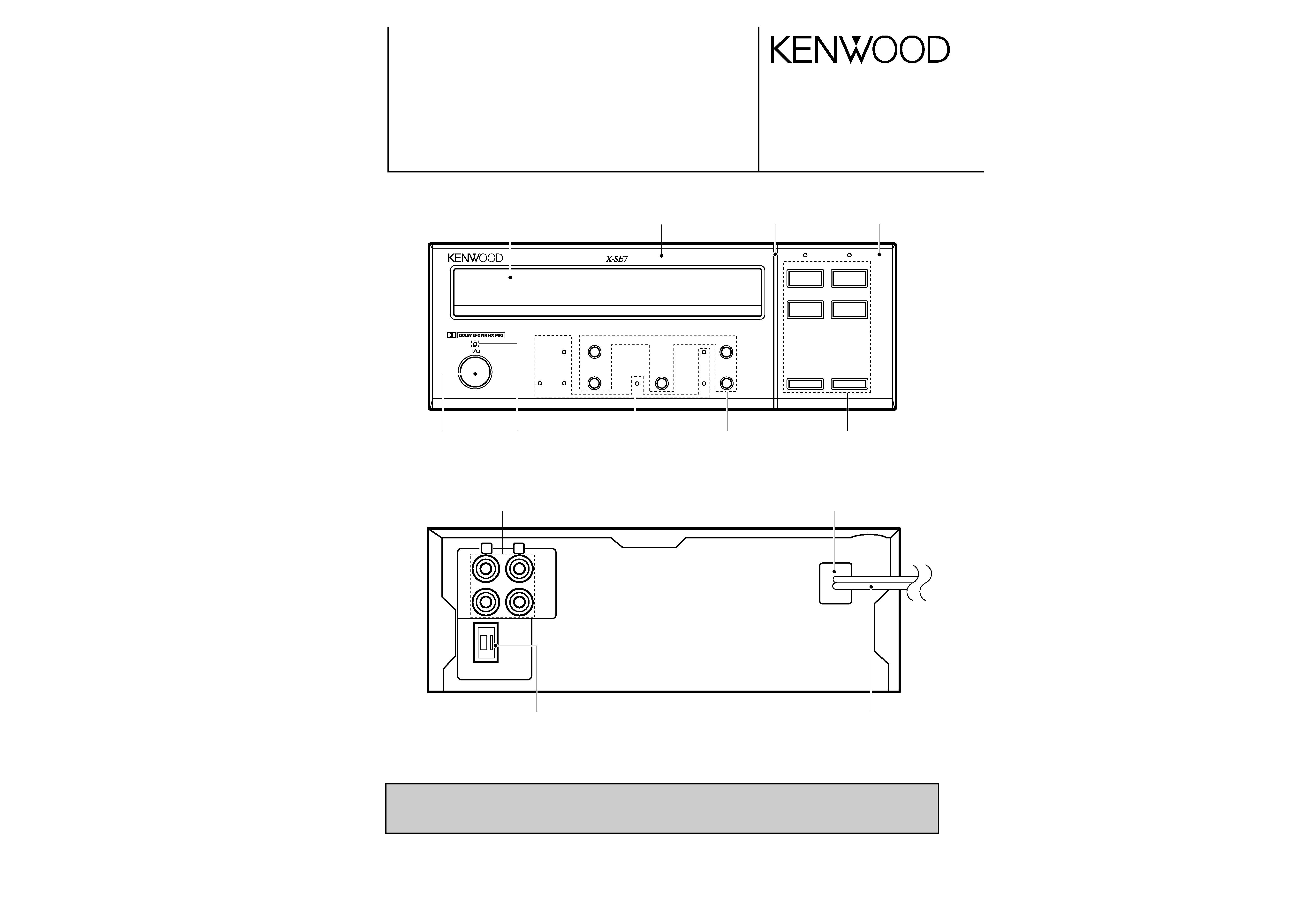
Phono jack
(E63-0046-15)
Rectangular receptacle
(E08-0311-05)
Power cord bushing
(J42-0083-05)
AC power cord *
(E30- )
STEREO AUTO REVERSE CASSETTE DECK
X-SE7/SE7(G)/SE9
SERVICE MANUAL
© 1997-8/B51-5342-00 (K/K) 3209
Illustration is X-SE7.
* Refer to parts list on page 14.
Refer to X-E9 and X-SA7 service manuals (B51-4926-00/B51-5214-00), if you
require in detail.
1
¡
7
2
8
3
stereo auto reverse cassette deck
on/standby
CRLS
rev. mode
Dolby NR
B
C
0
7 front loading mechanism 7
"
Panel
(A29-0873-03)
Panel *
(A60-)
Escutcheon
(B07-2363-04)
Panel
(A60-1202-03)
Knob
(K29-6744-04)
Sub panel
(A22-1779-11)
Indicator
(B12-0319-04)
Indicator
(B12-0319-04)
Knob
(K29-6745-13)
X-SE7(K) 1P 97.11.29 4:13 AM y[W 2
X-SE7/SE7(G)/SE9
2
CONTENTS / ACCESSORIES
DISASSEMBLY FOR REPAIR
CIRCUIT DESCRIPTION
CONTENTS / ACCESSORIES .................................. 2
DISASSEMBLY FOR REPAIR....................................2
CIRCUIT DESCRIPTION ............................................2
CONTROLS ................................................................3
ADJUSTMENT ............................................................4
PC BOARD ................................................................ 5
SCHEMATIC DIAGRAM ............................................ 7
EXPLODED VIEW ....................................................11
PARTS LIST..............................................................14
SPECIFICATIONS ......................................Back cover
Contents
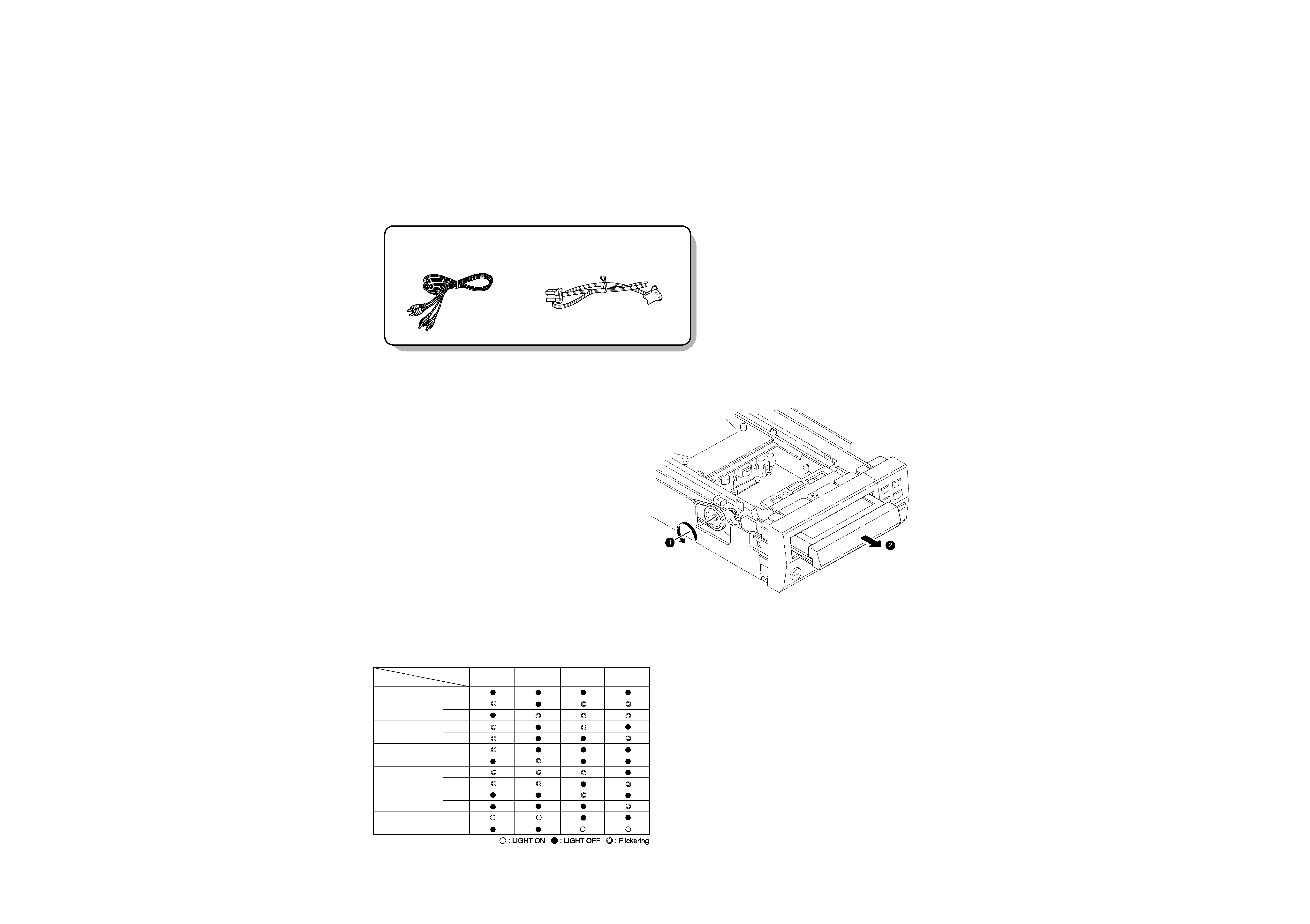
Accessories
5 Power does not turn on and tray does not come out.
1. Turn the pully in the direction of the arrow in the draw-
ing with a finger (
1).
2. If the tray comes out to the front side, pull out the tray
by hand forward the front (
2).
Audio cord (2)
(E30-0615-05)
System control cord (1)
(E30-2628-05)
LED
ITEM
POWER
DOLBY B
DOLBY C
RVS
MODE
UNDER ADJUSTMENT
PB CALIB
ERR
L
R
PB LEVEL
ERR
L
R
REC CALIB
ERR
L
R
REC LEBEL
ERR
L
R
BIAS DAC
ERR
L
R
PB ALL OK
ALL OK
V Correction of circuit description
LED indication state.
X-SE7(K) 1P 97.11.29 5:00 AM y[W 3
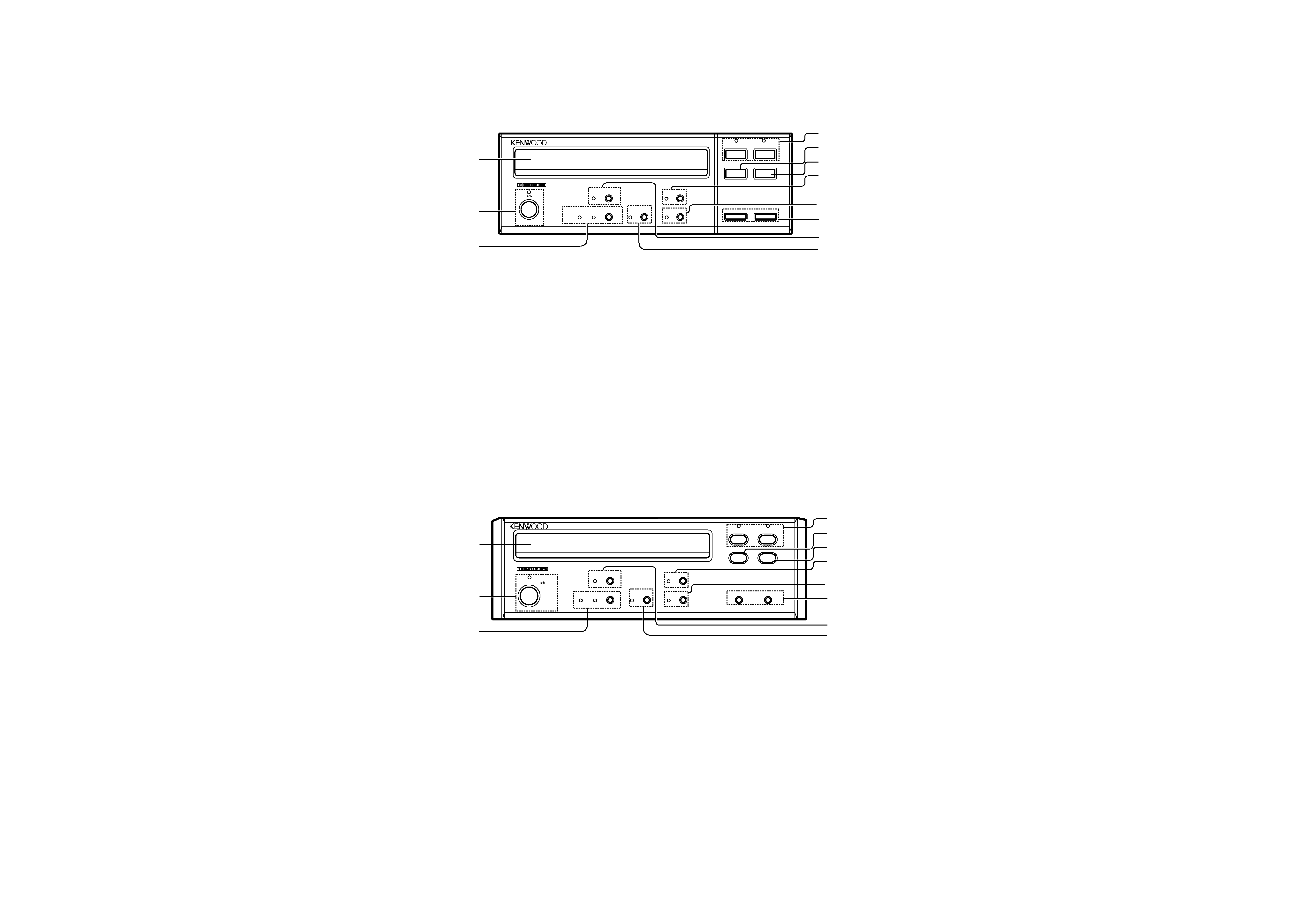
1 Tape tray
Load a cassette tape here.
2 "on/standby" key/indicator
Press to turn the power on/off (standby). This key is not
used when the unit is connected using the system
connection.
3 Dolby NR key/indicators
Press to switch the Dolby Noise Reduction on/off.
4 Play (2 3) keys/operation indicators
During stop and pause: the tape direction lights red.
During playback and recording: the tape direction lights
green.
During fast forward and rewind: the tape direction
flashes green.
5 Open/close (0) key
Press to open the tape tray when loading or
unloading tape.
6 Stop key (7)
7 Pause (8) key/indicator
8 Record (¶) key/indicator
Press to start recording. When pressed during recording,
the tape stops after leaving a non-recorded section
(blank) of about 4 seconds.
9 Fast forward and rewind (1 ¡) keys
0 "rev. mode" key/indicator
Press to switch the tape reverse mode (two-way or one-
way) of the deck.
! CRLS key/indicator
Press to set the recording level automatically according
to the recorded music source.
stereo auto reverse cassette deck
X-SE9
on/standby
rev. mode
Dolby NR
CRLS
B
C
"
1
0
2
7
3
¡
8
1
2
4
5
6
8
9
0
!
3
7
- front loading mechanism -
(X-SE9)
X-SE7/SE7(G)/SE9
3
CONTROLS
1 Tape tray
Load a cassette tape here.
2 "on/standby" key/indicator
Press to turn the power on/off (standby). This key is not
used when the unit is connected using the system
connection.
3 Dolby NR key/indicators
Press to switch the Dolby Noise Reduction on/off.
4 Play (2 3) keys/operation indicators
During stop and pause: the tape direction lights red.
During playback and recording: the tape direction lights
green.
During fast forward and rewind: the tape direction
flashes green.
5 Open/close (0) key
Press to open the tape tray when loading or
unloading tape.
6 Stop key (7)
7 Pause (8) key/indicator
8 Record (¶) key/indicator
Press to start recording. When pressed during recording,
the tape stops after leaving a non-recorded section
(blank) of about 4 seconds.
9 Fast forward and rewind (1 ¡) keys
0 "rev. mode" key/indicator
Press to switch the tape reverse mode (two-way or one-
way) of the deck.
! CRLS key/indicator
Press to set the recording level automatically according
to the recorded music source.
on/standby
rev. mode
Dolby NR
CRLS
B
C
1
0
2
7
3
¡
8
"
stereo auto reverse cassette deck
X-SE7
1
2
4
5
6
8
9
0
!
3
7
- front loading mechanism -
(X-SE7)
X-SE7(K) 1P 97.11.29 4:14 AM y[W 7
X-SE7/SE7(G)/SE9
4
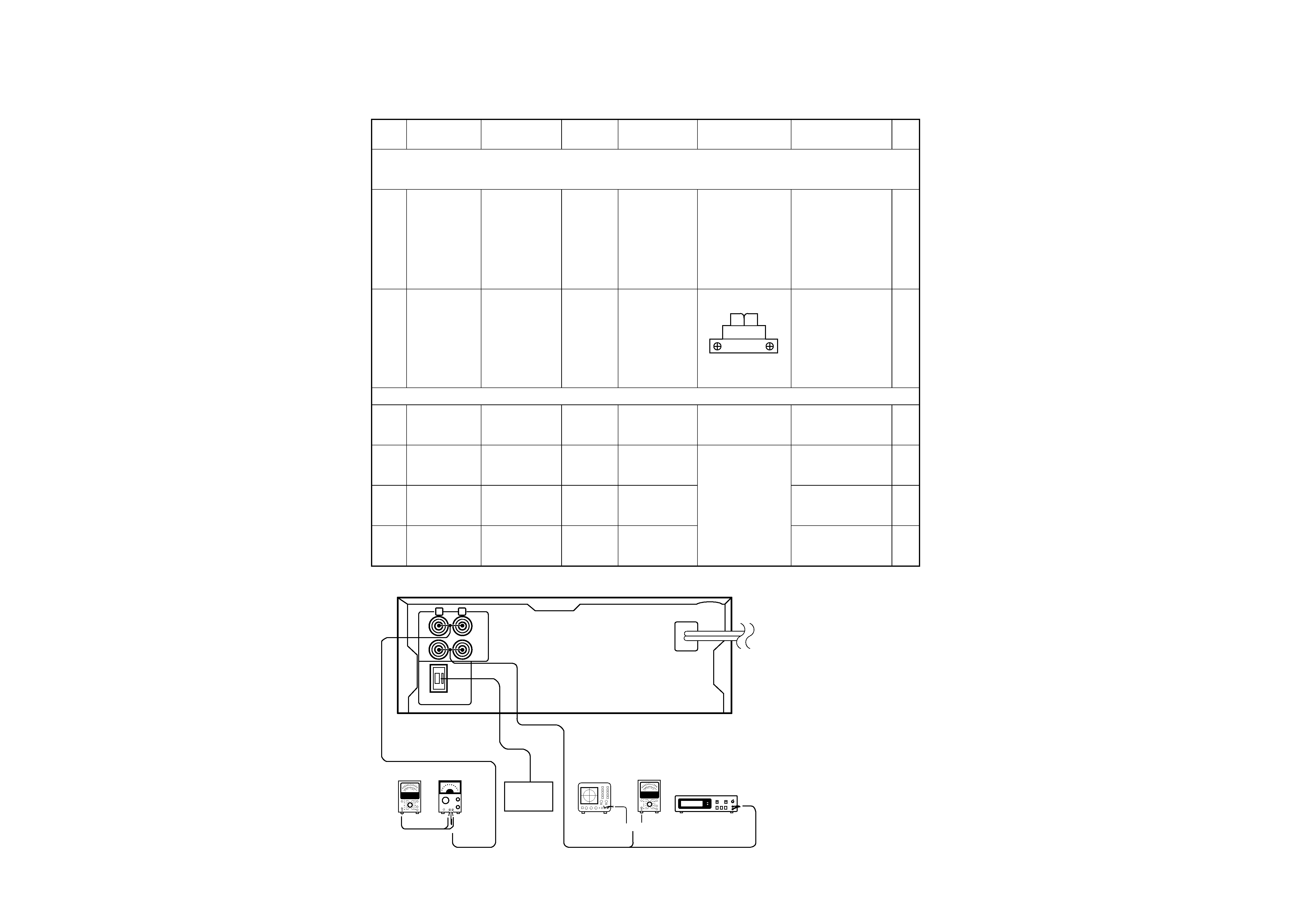
ADJUSTMENT
{
AC voltmeter
AC voltmeter
Oscilloscope
Distortion meter
AG
SYSTEM
CONTROL
REC
IN
PLAY
OUT
L
R
KSJ-0816
Order
Item
Input
setting
Output
setting
Deck
setting
Adjustment points
Adjustment method
Fig.
Unless otherwise specified, set the respective switches as follow :
TAPE : NORMAL
DOLBY : OFF
INPUT : REC IN
OUTPUT : PLAY OUT
I. Cassette mechanism section (Recording/play head adjustment)
< 1 >
Demagnetization
and cleaning
--
--
Power : OFF
Demagnetization,
cleaning, PLAY
Recording head,
erase head, capstan,
pinch roller
Demagnetize the REC/
PLAY head with the
head eraser. Clean the
REC/PLAY head, erase
head, capstan and
pinch roller using a
cotton swab slightly
damped with alcohol.
< 2 >
Azimuth of the
REC/PLAY head
TCC-153
MTT-114
10KHz, -10dB
LINE OUT
(Lch or Rch)
PLAY
Adjust the output to
maximum and adjust
the azimuth adjustment
screw for the Lissajous
waveform pattern of
the oscilloscope to
become close to a 45°
straight line.
II. Printed circuit board adjustment (X28-293)
(1)
Tape speed
(normal)
TCC-110
MTT-111
3KHz
(A)
PLAY
MOTOR VR.
Adjust so ; that the
frequency is 3KHz at
the tape center.
(2)
Playback level
TCC-130
400 Hz
(A)
MANUAL
ADJUSTMENT
MODE PLAY
ADJUSTMENT
VALUE
UP : [DOLBY] KEY
DOWN : [RVS
PLAY] KEY
CHANGE OF
ADJUSTMENT
MODE [CRLS] KEY
Output level : -1dBs
(3)
Bias current
TCC-108A
12.5KHz, -21dBm
(A)
MANUAL
TEST MODE
REC and PLAY
-21dBm
(4)
Recording level
TCC-108A
400Hz, -21dB
(A)
MANUAL
TEST MODE
REC and PLAY
-21dBm
RVS
FWD
5 The method of the manual adjust-
ment mode.
(1) Setting
Shorting the TEST pin of (X28-
)(A/5) TP5 --
w-- TP4 with the
diode, plug the power cord to the
AC wall let.
(2) Refer to manual adjustment
mode(3-3), if require more
details.
(A) Measurement Equipment Connection
X-SE7(K) 1P 97.11.29 4:14 AM y[W 8
ACE
G
I
BD
F
H
J
2
1
3
5
7
4
6
E
B
1
64
41
24
80
65
40
25
1
1
10
1
6
13
BE
1
3
1
10
1
3
9
1
1
1
1
1
112
10
1
10
15
5
12
18
10
B
E
B
B
B
B
B
E
B
E
E
E
E
E
1
9
E
E
B
B
15
1
10
1
I
BE
B
E
B
E
G
O
REC IN
PLAY
OUT
SYSTEM
CONTROL
AC
OUTLET
E
B
E
B
E
B
E
E
B
E
E
B
B
B
B
E
B
E
B
EB
E
EB
E
B
E
B
E
B
E
B
EB
EB
E
B
E
E
E
E
B
B
B
B
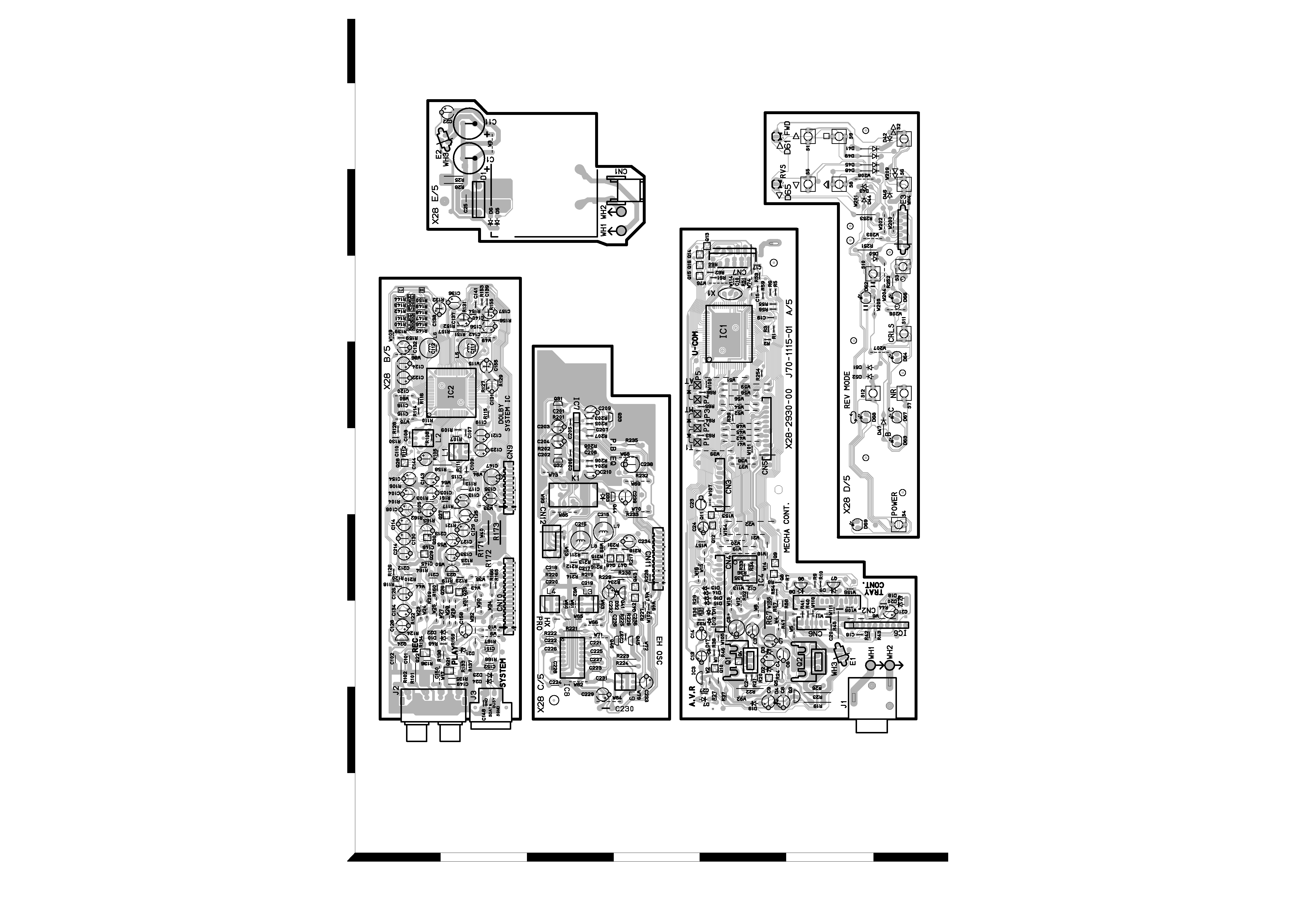
Refer to the schematic diagram for the value of resistors and capacitors.
PC BOARD(Component side view)
5
6
X-SE7(K)PCB/SD( 97.11.294:19AM y[W 2