
B60-4487-10 01 CH (K, P, T, M, X, Y) OC 9911
VR-4090/VR-4080
KRF-V7773D
This instruction manual is used to describe multiple models listed above.
Model availability and features (functions) may differ depending on the country and sales area.
ii
Welcome to the Connection and Setup Guide for your new
Kenwood Audio-Video Receiver. This manual covers two
models.
VR-4090/VR-4080 is sold in USA and Canada.
KRF-V7773D is sold in other countries.
The VR-4090/VR-4080/KRF-V7773D offers 3 kinds of 5.1-
channel digital decoding:
·
Dolby® Digital, for the hundreds of currently available
Dolby Digital DVDs and LaserDiscs.
·
DTS®, a well-established multichannel format in movie
theaters, is available for home theater on LaserDisc and
DVD.
·
MPEG 2 Audio Multichannel format
Connecting and Setting Up Your New Kenwood Audio-Video Receiver
Use it to connect all your current audio and video com-
ponents--the VR-4090/VR-4080/KRF-V7773D has a vari-
ety of connection jacks so you can customize your enter-
tainment setup.
It also includes Kenwood's remarkable LCD remote con-
trol unit.
Manufactured under license from Dolby Laboratories.
"Dolby", "AC-3", "Pro Logic", and the double-D symbol
are trademarks of Dolby Laboratories. Confidential Unpub-
lished Works. © 1992-1997 Dolby Laboratories. All rights
reserved.
Manufactured under license from Digital Theater Systems,
Inc. US Pat. No. 5,451,942 and other worldwide patents
issues and pending. "DTS" and "DTS Digital Surround" are
trademarks of Digital Theater Systems, Inc. © 1996 Digital
Theater Systems, Inc. All rights reserved.
The above are additional trademarked names appearing in
this manual. All other products named are trademarks of
their respective companies.
As an
ENERGY STAR® Partner,
Kenwood Corporation has deter-
mined that this products meets the
ENERGY STAR® guidelines for energy
efficiency.
This product can save energy. Saving energy reduces air pol-
lution and lowers utility bills.
, HDCD®, High Definition Compatible Digital® and
Pacific MicrosonicsTM are either registered trademarks or
trademarks of Pacific Microsonics, Inc. in the United States
and/or other countries. HDCD system manufactured under
license from Pacific Microsonics, Inc. This product is cov-
ered by one or more of the following: IN the USA: 5,479,168,
5,638,074, 5,640,161, 5,808,574, 5,838,274, 5,854,600,
5,864,311, 5,872,531, and in Australia: 669114. Other pat-
ents pending.
D.R.I.V.E. circuit: This is a KENWOOD original technology
for reproducing signals with high resolution by instant
switching of the internal filters according to the input sig-
nal. The VR-4090, VR-4080 and KRF-V7773D incorporate a
high performance DSP to provide very high resolution from
a 32-bit DRIVE III circuit, achieving stereo audio reproduc-
tion with the best quality ever reached.
HDCD®: This is a new format of high-resolution recording.
The VR-4090, VR-4080 and KRF-V7773D are capable of re-
producing CDs recorded in the HDCD format with high
resolution and wide dynamic range.
iii
Before Applying Power
Read this section carefully to ensure safe operation.
THE LIGHTNING FLASH WITH ARROWHEAD SYMBOL, WITHIN AN EQUILATERAL TRIANGLE,
IS INTENDED TO ALERT THE USER TO THE PRESENCE OF UNINSULATED "DANGEROUS
VOLTAGE" WITHIN THE PRODUCT'S ENCLOSURE THAT MAY BE OF SUFFICIENT MAGNI-
TUDE TO CONSTITUTE A RISK OF ELECTRIC SHOCK TO PERSONS.
CAUTION
RISK OF ELECTRIC SHOCK
DO NOT OPEN
CAUTION: TO REDUCE THE RISK OF ELECTRIC SHOCK, DO
NOT REMOVE COVER (OR BACK). NO USER-SERVICEABLE
PARTS INSIDE. REFER SERVICING TO QUALIFIED SERVICE
PERSONNEL.
THE EXCLAMATION POINT WITHIN AN EQUILATERAL TRIANGLE IS INTENDED TO ALERT
THE USER TO THE PRESENCE OF IMPORTANT OPERATING AND MAINTENANCE (SERVIC-
ING) INSTRUCTIONS IN THE LITERATURE ACCOMPANYING THE APPLIANCE.
VR-4090/VR-4080/KRF-V7773D is designed for operation
as follows.
U.S.A. and Canada ................................ AC 120 V only
Europe and U.K. ................................... AC 230 V only
Australia ................................................ AC 240 V only
*Other countries
................................ AC 110-120/220-240 V switchable
For the United Kingdom
WARNING :
TO PREVENT FIRE OR ELECTRIC SHOCK, DO NOT EXPOSE THIS APPLIANCE
TO RAIN OR MOISTURE.
*AC voltage selection
Note:
Our warranty does not cover damage caused by excessive
line voltage due to improper setting of the AC voltage selec-
tor switch.
AC voltage selector switch
Move switch lever to match your line voltage with a small
screwdriver or other pointed tool.
The AC voltage selector switch on the rear panel is set to the
voltage that prevails in the area to which the unit is shipped.
Before connecting the power cord to your AC outlet, make
sure that the setting position of this switch matches your
line voltage. If not, it must be set to your voltage in accor-
dance with the following direction.
Safety Precautions
Read this section carefully to ensure safe operation.
Factory fitted moulded mains plug
1. The mains plug contains a fuse. For replacement, use
only a 13-Amp ASTA-approved (BS1362) fuse.
2. The fuse cover must be refitted when replacing the
fuse in the moulded plug.
3. Do not cut off the mains plug from this equipment.
If the plug fitted is not suitable for the power points
in your home or the cable is too short to reach a
power point, then obtain an appropriate safety ap-
proved extension lead or adapter, or consult your
dealer.
If nonetheless the mains plug is cut off, remove the
fuse and dispose of the plug immediately, to avoid a
possible shock hazard by inadvertent connection to
the mains supply.
IMPORTANT : The wires in the mains lead are coloured
in accordance with the following code:
Blue
: Neutral
Brown : Live
Do not connect those leads to the earth terminal of a
three-pin plug.
AC 110 ~120V / AC220 ~ 240V
50/60Hz SWITCHD
TOTAL 90W MAX
AC 110-
120V
AC 220-
240V
iv
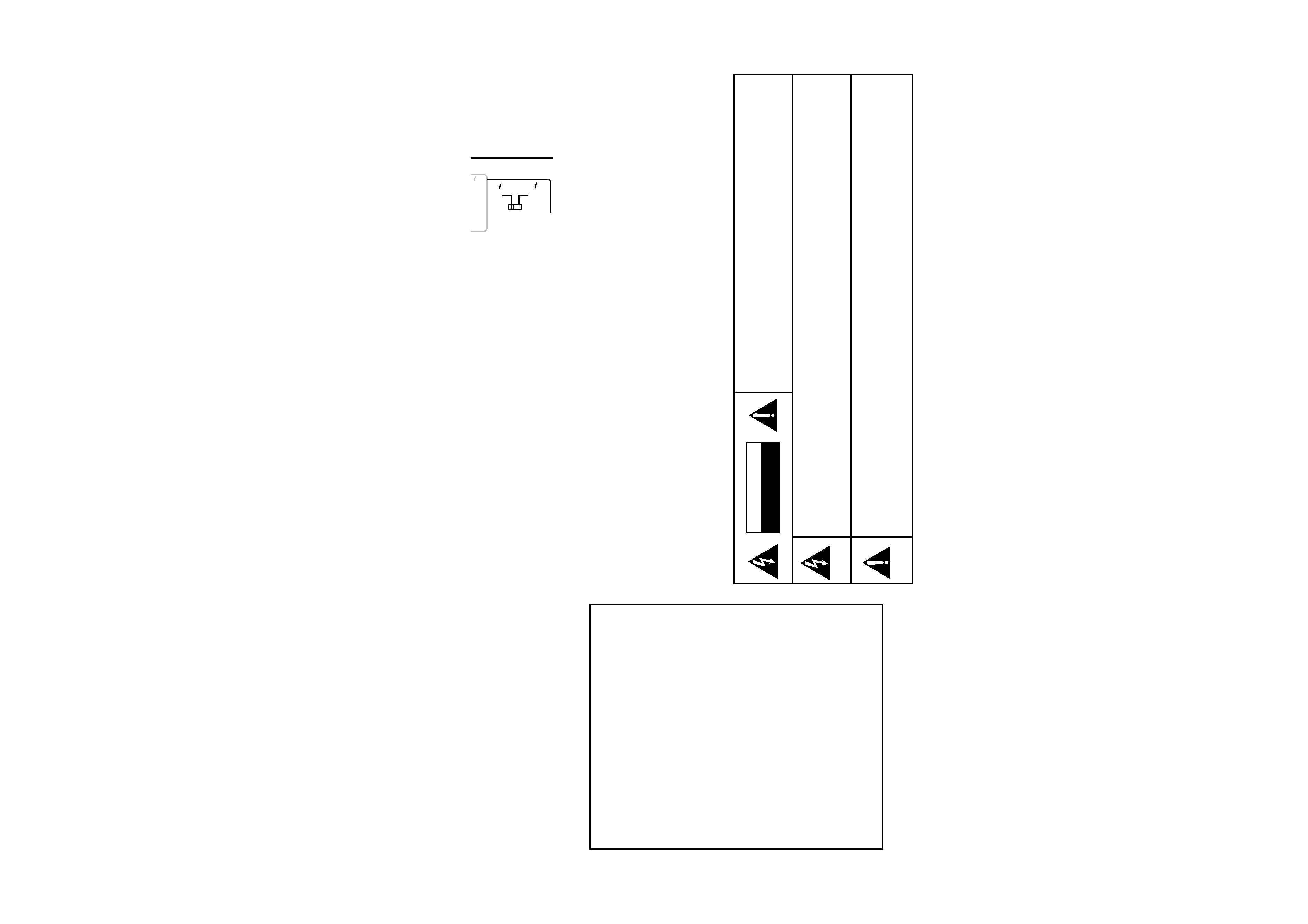
CHANNEL SPACE / DE-EMPHASIS Switch
Not present for USA, Canada, U.K. and Australia
The CHANNEL SPACE / DE-EMPHASIS switch on the rear
panel is set to the correct setting that prevails in the area to
which the unit is shipped. However, if the CHANNEL SPACE
/ DE-EMPHASIS setting is not matched to the area where
the unit is to be used; for instance, if you move from area 1
to area 2 as shown in the table to the right or vice versa,
desired reception of AM / FM broadcasts is not expected.
In this case, change the CHANNEL SPACE / DE-EMPHASIS
setting in accordance with the area corresponding to the
table. The CHANNEL SPACE / DE-EMPHASIS is switched
over at the same time.
·
When changing the setting of the CHANNEL SPACE /
DE-EMPHASIS switch, first unplug the power cord, and
then reset the switch, plug the power cord back in, and
turn the power switch on.
CHANNEL SPACE
DE-EMPHASIS switch
Area
CHANNEL
SPACE freq.
DE-
EMPHASIS
USA, Canada,
and South
American
Countries
Other
Countries
1
2
FM : 100 kHz
AM : 10 kHz
FM : 50 kHz
AM :
9 kHz
75
µs
50
µs
ND
AM
50
µs
FM 50kHz
AM 9kHz
75
µs
FM 100kHz
AM 10kHz
DE-EMPHASIS
CHANNEL SPACE
RF
REMOTE
CONTROL
UNIT
RC-R0910
2WAY
LCD
REMOTE
CONTROL
UNIT
+
-
+
-
12
3
45
6
78
9
10
11
12
+10
0
+100
/8
/7
1
1
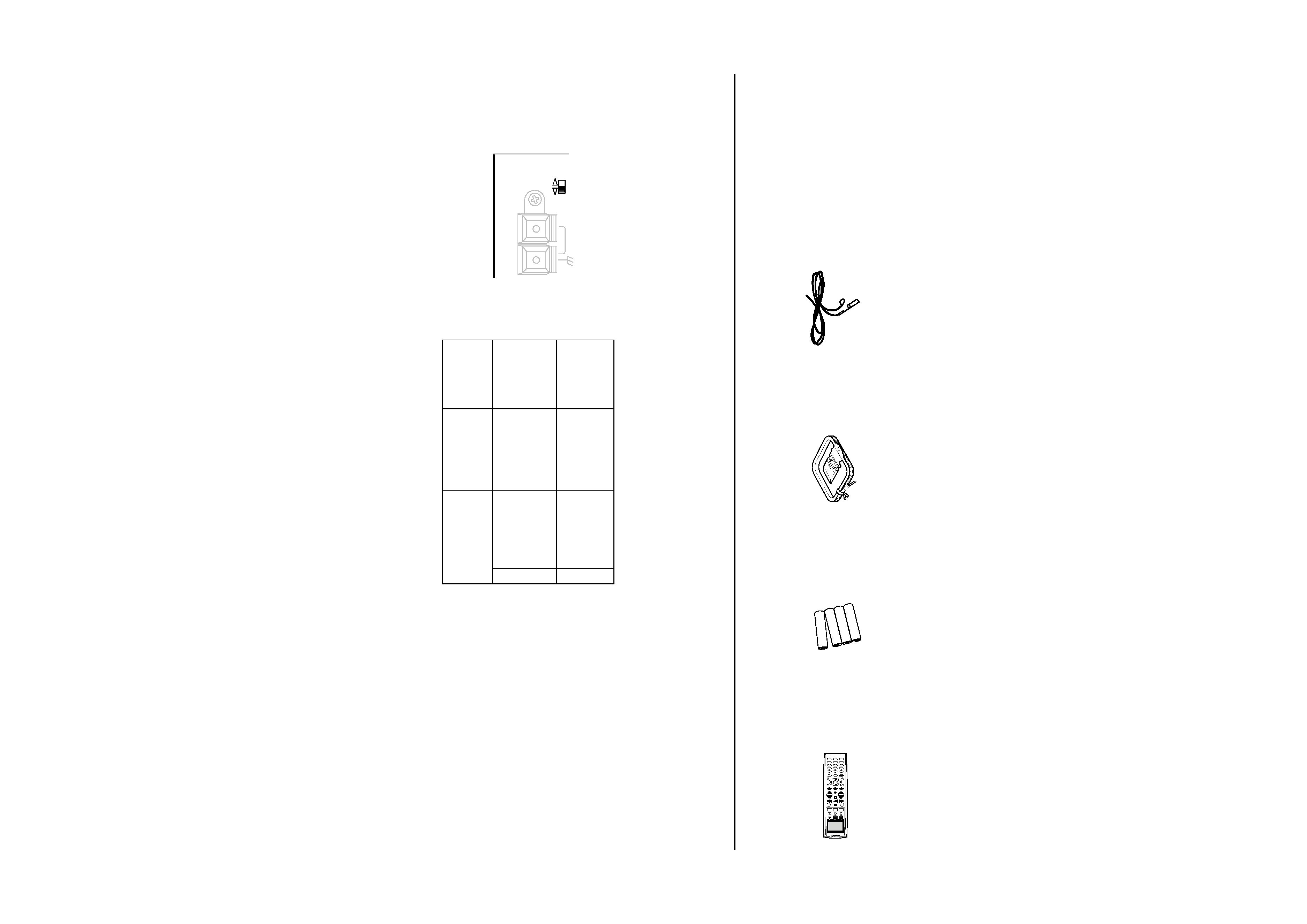
Unpacking
If any accessories are missing, or if the receiver is damaged or fails to operate, notify your dealer immediately. If your receiver was shipped to you
directly, notify your shipper immediately. Kenwood recommends that you retain the original carton and packing materials in case you need to
move or ship the receiver in the future.
Unpack your new receiver carefully and make sure that all the accessories are present:
Remote control unit
Batteries
AM Loop Antenna
FM Antenna

v
Table of Contents
Chapter One : Connecting Your
Devices .................................................. 1
Noting Your Devices .............................................. 3
Connecting Your Speakers .................................... 4
To Connect Front Speakers Only
To Connect Front and Surround Sound
Speakers
What if I Have a Powered Subwoofer?
What if I Have an Amplifier?
Connecting Your TV .............................................. 8
To Connect a TV
What if I Want to Watch TV without Turning
on the Receiver?
Connecting Your Cable TV or Satellite Tuner ..... 10
To Connect a Cable TV Tuner with a Com-
posite (RCA) Video Output
To Connect a Cable TV Tuner without a
Composite (RCA) Video Output
To Connect a Satellite Tuner
Connecting Your VCR(s) ..................................... 12
To Connect a Primary VCR
To Connect a Second VCR
Connecting Your Primary CD Player .................. 14
What if I Have a Video CD-Compatible CD
Player?
To Connect a Kenwood 200-Disc CD
Changer
To Connect Any Other Primary CD Player or
Changer
To Connect a Second CD Player
Connecting Your DVD Player .............................. 16
To Connect a DVD Player
Connecting Your CD-R Recorder ........................ 18
To Connect an CD-R Recorder
Connecting Your MD Recorder or Primary
Tape Deck ......................................................... 20
To Connect an MD Recorder
To Connect a Primary Tape Deck
To Connect a Secondary Tape Deck
Connecting Your Secondary CD Player or
Tape Deck ......................................................... 22
To Connect a Secondary CD Player
To Connect a Secondary Tape Deck
Connecting Your Laser Disc Player
(with AC-3 RF Output) ..................................... 24
To Connect an AC-3 RF Output Laser Disc
Player
Connecting Your Laser Disc Player
(without AC-3 RF Output) ............................... 26
To Connect a PCM Digital Output Laser Disc
Player
Connecting Your Turntable/Record Player ......... 28
To Connect a Turntable/Record Player
Connecting a Camcorder or Additional VCR ..... 29
To Connect a Camcorder or Additional VCR
Can I Connect an Additional VCR Perma-
nently?
Connecting an External IR Receiver and IR Repeat-
ers ..................................................................... 30
To Connect a KENWOOD IR-9991 IR
Receiver
To Connect any Other IR Receiver
To Connect IR Repeaters
What if I Have Several Kenwood Components
(System Control Chaining)? ............................ 32
System Control connection allows you to
Connecting the Antennas .................................... 33
AM Loop Antenna
FM Indoor Antenna
FM Outdoor Antenna
RF Remote Antenna
What if I Have Cable Radio?
Chapter Two : Setting Up the Remote
Control unit ........................................ 34
Installing the Batteries ........................................ 34