
TS-570S
4
6
2
L
O
W
C
U
T
H
IG
H
C
U
T
4
6
2
PF
PF
ATT
ATT
PRE-AMP
PRE-AMP
VOX
VOX
PROC
PROC
SEND
SEND
CH1
CH1
MIC
MIC
CW
CW
FSK
FSK
LSB
LSB
USB
USB
FM
FM
AM
AM
AT TUNE
AT TUNE
POWER
POWER
HF TRANSCEIVER TS-570D
HF TRANSCEIVER TS-570D
PHONES
PHONES
1
CH2
CH2
2
CH3
CH3
3
ANT
ANT
4
REC
REC
5
FINE
FINE
6
NB
NB
7
AGC/TONE
AGC/TONE
8
REV
REV
9
CLR
CLR
F.LOCK
F.LOCK
0
ENT
ENT
MIC
MIC
PWR
PWR
KEY
KEY
DELAY
DELAY
MENU
MENU
1MHz
1MHz
SPLIT
SPLIT
M/V
M/V
DOWN
DOWN
UP
UP
MR
MR
TF-SET
TF-SET
A=B
A=B
SCAN
SCAN
M>VFO
M>VFO
M.IN
M.IN
M.IN
M.IN
FILTER
FILTER
CW TUNE
CW TUNE
B.C.
B.C.
N.R.
N.R.
A/B
A/B
CLEAR
CLEAR
RIT
RIT
XIT
XIT
RIT/XIT
RIT/XIT
IF SHIFT
IF SHIFT
SQL
SQL
CH
CH
0
10
10
8
A F
A F
R F
R F
HIGH
HIGH
DSP SLOPE
DSP SLOPE
LOW
LOW
0
10
10
8
+
Intelligent Digital Enhanced Communications System
© B62-0898-00 (K,E,M)(MC)
09 08 07 06 05 04 03 02 01 00
KENWOOD CORPORATION
INSTRUCTION MANUAL
ALL MODE MULTI-BANDER
TS-570D
HF TRANSCEIVER
INFORMATION TO THE DIGITAL DEVICE USER REQUIRED
BY THE FCC
This equipment has been tested and found to comply with the
limits for a Class B digital device, pursuant to Part 15 of the FCC
Rules. These limits are designed to provide reasonable
protection against harmful interference in a residential
installation.
This equipment generates, uses and can generate radio
frequency energy and, if not installed and used in accordance
with the instructions, may cause harmful interference to radio
communications. However, there is no guarantee that the
interference will not occur in a particular installation. If this
equipment does cause harmful interference to radio or television
reception, which can be determined by turning the equipment off
and on, the user is encouraged to try to correct the interference
by one or more of the following measures:
·
Reorient or relocate the receiving antenna.
·
Increase the separation between the equipment and
receiver.
·
Connect the equipment to an outlet on a circuit different from
that to which the receiver is connected.
·
Consult the dealer for technical assistance.
FCC WARNING
This equipment generates or uses radio frequency energy.
Changes or modifications to this equipment may cause harmful
interference unless the modifications are expressly approved in
the instruction manual. The user could lose the authority to
operate this equipment if an unauthorized change or modification
is made.
APPLICABLE MODEL
This manual applies to the following model:
TS-570S: All mode multi-bander
TS-570D: HF Transceiver
Intelligent Digital Enhanced Communications System
SUPPLIED ACCESSORIES
Carefully unpack the transceiver. We recommend that
you identify the items listed in the table below. In
addition, it is safe to keep the box and the packing
material. You may need to repack the transceiver in
the future.
NOTICE TO THE USER
One or more of the following statements may be
applicable to this equipment.
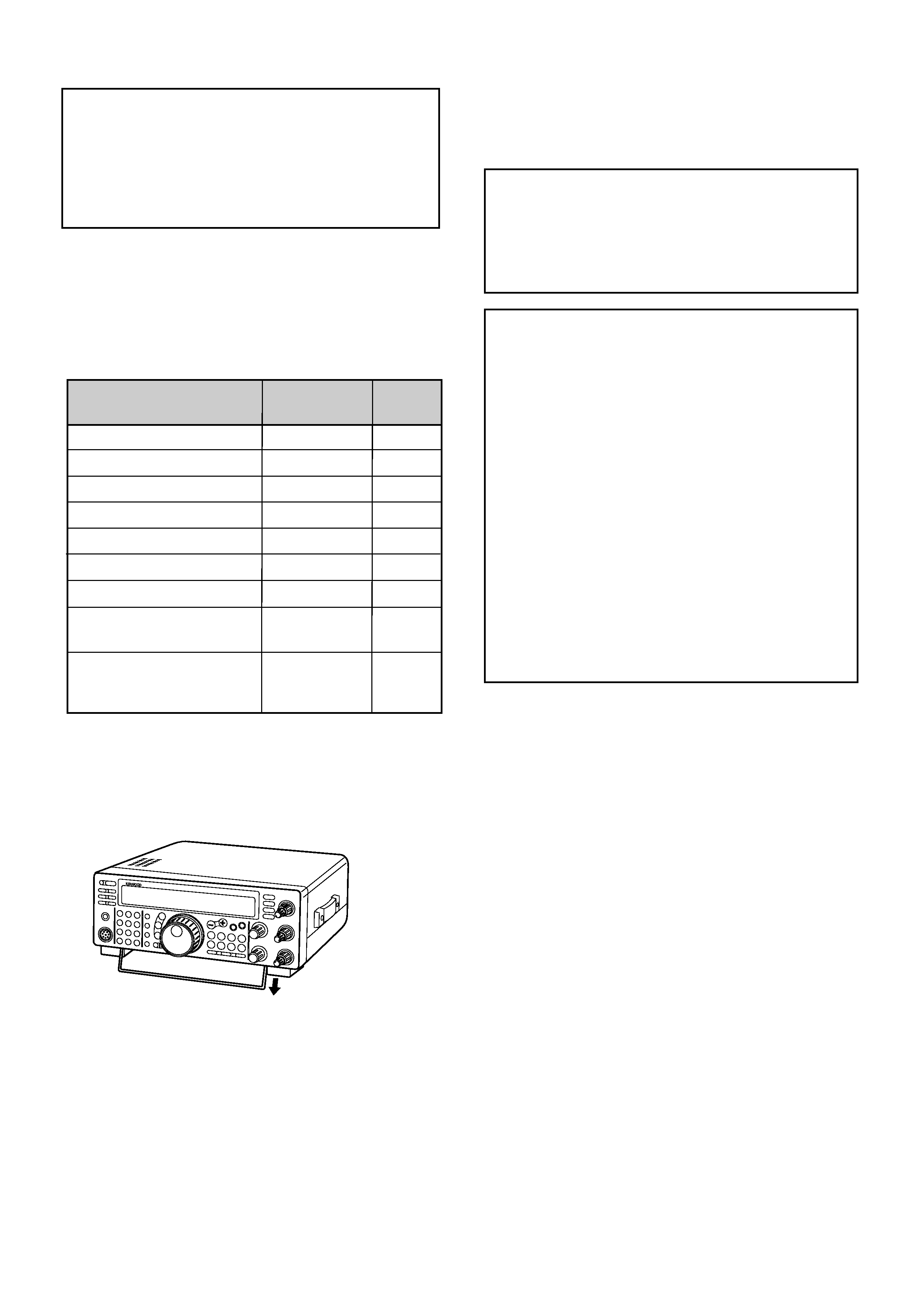
This transceiver is equipped with a bail on the bottom so
that you can angle the transceiver. Pull the bail forward
to the limit as shown:
Microphone
DC power cable
7-pin DIN plug
13-pin DIN plug
Fuse (25 A)
Fuse (4 A)
Instruction manual
Schematic/block diagrams
(U.S.A. and Canada only)
Warranty card
(U.S.A., Canada, and
Europe only)
1
1
1
1
1
1
1
1
1
Accessory
Part Number
Quantity
1
1
T91-0352-XX
E30-3157-XX
E07-0751-XX
E07-1351-XX
F05-2531-XX
F06-4027-XX
B62-0898-XX
--
--
For other markets, schematic and block diagrams are
available as options.

i
Thank you for choosing the KENWOOD TS-570 series.
This Intelligent Digital Enhanced Communications
System was developed by a team of engineers
determined to continue the tradition of excellence and
innovation in KENWOOD HF transceivers.
This transceiver includes a 16-bit Digital Signal
Processing (DSP) unit to process audio frequencies. By
taking maximum advantage of DSP technology the
transceiver gives you enhanced interference reduction
capabilities and improves the quality of audio that you
transmit. You will find the differences when you fight
QRM and QRN in the new solar cycle. As you learn
how to use this transceiver, you also will find
KENWOOD is pursuing "user friendliness". For
example, each time you change the Menu No. in Menu
mode, you will see, on the display, scrolling messages
that tell what you are selecting.
Though user friendly, this transceiver is technically
sophisticated and some features may be new to you.
Consider this manual to be a personal tutorial from the
designers. Allow the manual to guide you through the
learning process now, then act as a reference in the
coming years.
FEATURES
Taking full advantage of DSP technology, this
transceiver
·
Provides high performance receive filters.
·
Enhances the Beat Cancel and Noise Reduction
tools.
·
Allows total customization of transmitted audio
through the use of functions such as the Transmit
Equalizer.
·
Enables Automatic Zero-beating for CW operation.
To pursue user friendliness, this transceiver
·
When in Menu mode, scrolls messages to tell you
what you are selecting.
·
Allows you to quickly and easily save the current
transceiver settings in Quick memory.
·
Is equipped with a large, easy to read LCD display.
WRITING CONVENTIONS FOLLOWED
The writing conventions described below have been
followed to simplify instructions and avoid unnecessary
repetition. This format is less confusing for the reader.
Reviewing the following information now will reduce
your learning period. That means less time will be
spent reading this manual; more time will be available
for operating.
Furthermore, a system of advisories is used as follows:
WARNING! ¬ Possibility of personal injury
CAUTION: ¬ Possibility of equipment damage
Note:
¬ Important information or operating tip
Note:
Basic procedures are numbered sequentially to guide you
step-by-step. Additional information pertaining to a step, but not
essential to complete the procedure, is provided in bulleted form
following many steps.
THANK YOU
Instruction
What to Do
Press and release KEY.
Press and hold KEY1 down,
then press KEY2. If there are
more than two keys, press and
hold down each key in turn
until the final key has been
pressed.
Press KEY1 momentarily,
release KEY1, then press
KEY2.
With the transceiver power
OFF, press and hold KEY,
then switch ON the transceiver
power by pressing the
POWER switch.
Press [KEY].
Press
[KEY1]+[KEY2].
Press
[KEY1], [KEY2].
Press
[KEY]+ POWER ON.
ii
PRECAUTIONS
IV
CHAPTER 1
INSTALLATION
1
ANTENNA CONNECTION ....................................... 1
GROUND CONNECTION ........................................ 2
LIGHTNING PROTECTION ..................................... 2
DC POWER SUPPLY CONNECTION ..................... 2
REPLACING FUSES ........................................... 2
ACCESSORY CONNECTIONS .............................. 3
FRONT PANEL .................................................... 3
Headphones (PHONES) ................................ 3
Microphone (MIC) ........................................... 3
REAR PANEL ...................................................... 3
External Speaker (EXT SP) ............................ 3
Keys and Keyboards for
CW Operation (PADDLE and KEY) ................ 3
CHAPTER 2
YOUR FIRST QSO
4
RECEIVING ............................................................. 4
TRANSMITTING ...................................................... 5
CHAPTER 3
GETTING ACQUAINTED
6
FRONT PANEL ........................................................ 6
MICROPHONE ........................................................ 9
REAR PANEL ........................................................ 10
DISPLAY ................................................................ 11
CHAPTER 4
OPERATING BASICS
13
SWITCHING POWER ON/OFF .............................. 13
ADJUSTING VOLUME ........................................... 13
AUDIO FREQUENCY (AF) GAIN ...................... 13
RADIO FREQUENCY (RF) GAIN ...................... 13
SELECTING VFO A OR VFO B .............................. 13
SELECTING A BAND ............................................. 13
SELECTING A MODE ............................................ 14
ADJUSTING SQUELCH ........................................ 14
SELECTING A FREQUENCY ................................ 14
FRONT PANEL METER ......................................... 14
TRANSMITTING .................................................... 15
SELECTING TRANSMIT POWER .................... 15
MICROPHONE GAIN ........................................ 15
CHAPTER 5
MENU SETUP
16
WHAT IS A MENU? ................................................ 16
MENU A/ MENU B ................................................. 16
MENU ACCESS ..................................................... 16
MENU CONFIGURATION ...................................... 17
CROSS REFERENCE FOR
MENU FUNCTIONS .............................................. 19
CHAPTER 6
BASIC COMMUNICATING
20
SSB TRANSMISSION ............................................ 20
CW TRANSMISSION ............................................. 21
AUTO ZERO-BEAT ............................................ 21
TX SIDETONE/ RX PITCH FREQUENCY ......... 21
FM TRANSMISSION .............................................. 22
TX DEVIATION SELECTION ............................. 22
CONTENTS
AM TRANSMISSION ............................................. 22
CHAPTER 7
SPECIALIZED COMMUNICATING
23
SPLIT-FREQUENCY OPERATION ....................... 23
TF-SET (TRANSMIT FREQUENCY SET) ......... 23
FM REPEATER OPERATION ................................ 24
SELECTING SUBTONE FREQUENCY ............. 25
CONTINUOUS OR BURST SUBTONES? ......... 25
FM CTCSS OPERATION ....................................... 25
DIGITAL OPERATION ............................................ 26
RTTY (FREQUENCY SHIFT KEYING) .............. 26
AMTOR/ PACKET/ PACTOR/ G-TORTM/ CLOVER 27
SLOW SCAN TV/ FACSIMILE ................................ 28
SATELLITE OPERATION ....................................... 28
CHAPTER 8
COMMUNICATING AIDS
29
RECEIVING ........................................................... 29
SELECTING YOUR FREQUENCY ................... 29
Direct Frequency Entry .................................. 29
Using 1 MHz Steps ....................................... 29
Quick Changes ............................................. 29
Fine Tuning ................................................... 29
Equalizing VFO Frequencies (A=B) .............. 30
RIT (RECEIVE INCREMENTAL TUNING) ......... 30
AGC (AUTOMATIC GAIN CONTROL) ............... 30
RX EQUALIZER ................................................ 30
TRANSMITTING .................................................... 31
VOX (VOICE-OPERATED TRANSMIT) ............. 31
Microphone Input Level ................................. 31
Delay Time .................................................... 31
SPEECH PROCESSOR .................................... 32
XIT (TRANSMIT INCREMENTAL TUNING) ....... 32
CUSTOMIZING TRANSMIT SIGNAL
CHARACTERISTICS ......................................... 33
Changing Transmit
Bandwidth (SSB/AM) .................................... 33
Equalizing Transmit Audio (SSB/FM/AM) ...... 33
MONITORING TRANSMITTED SIGNALS ......... 33
TRANSMIT INHIBIT ........................................... 33
CHANGING FREQUENCY WHILE
TRANSMITTING ................................................ 33
CW BREAK-IN ....................................................... 34
USING SEMI BREAK-IN OR
FULL BREAK-IN ................................................ 34
ELECTRONIC KEYER ........................................... 34
CHANGING KEYING SPEED ............................ 34
AUTO WEIGHTING ........................................... 34
Reversible Auto Weighting ............................ 34
CHANGING LOCKED-WEIGHT ........................ 35
BUG KEY FUNCTION ........................................ 35
CW MESSAGE MEMORY ................................. 35
Storing CW Messages .................................. 35
Checking CW Messages without Transmitting35
Transmitting CW Messages .......................... 35
CHAPTER 9
REJECTING INTERFERENCE
36
IF FILTER .............................................................. 36
CHANGING IF FILTER BANDWIDTH ............... 36
IF SHIFT ............................................................ 36
NOISE BLANKER .................................................. 36
iii
1
2
3
4
5
6
7
8
9
10
11
12
13
14
15
16
Transferring Data .......................................... 50
Receiving Data ............................................. 50
COMPUTER CONTROL ........................................ 51
SETTING UP ..................................................... 51
Equipment Needed ....................................... 51
Connections .................................................. 51
COMMUNICATION PARAMETERS .................. 51
USING A TRANSVERTER ..................................... 51
AUTOMATIC ANTENNA TUNER ............................52
PRESETTING .................................................... 52
DRU-3A DIGITAL RECORDING UNIT
(OPTIONAL) .......................................................... 53
RECORDING MESSAGES ................................ 53
MESSAGE PLAYBACK ...................................... 53
Checking Messages ...................................... 53
Sending Messages ....................................... 54
Changing Inter-message Interval .................. 54
Changing Volume .......................................... 54
VS-3 VOICE SYNTHESIZER (OPTIONAL) ........... 55
CHAPTER 13
OPTIONAL ACCESSORIES
56
CHAPTER 14
INSTALLING OPTIONS
57
REMOVING THE BOTTOM CASE ........................ 57
DRU-3A DIGITAL RECORDING UNIT ................... 57
VS-3 VOICE SYNTHESIZER UNIT ....................... 58
YK-88C-1/ YK-88CN-1/ YK-88SN-1 FILTERS ........ 58
SO-2 TEMPERATURE-COMPENSATED CRYSTAL
OSCILLATOR (TCXO) ........................................... 59
CHAPTER 15
CONNECTING PERIPHERAL EQUIPMENT 60
COMPUTER .......................................................... 60
COMPATIBLE TRANSCEIVER .............................. 60
RTTY EQUIPMENT ............................................... 61
LINEAR AMPLIFIER .............................................. 61
ANTENNA TUNER ................................................ 61
MCP AND TNC ...................................................... 62
CHAPTER 16
MAINTENANCE
63
GENERAL INFORMATION .................................... 63
SERVICE ........................................................... 63
SERVICE NOTE ................................................ 63
CLEANING ........................................................ 63
INTERNAL ADJUSTMENTS .................................. 64
REFERENCE FREQUENCY CALIBRATION ..... 64
ACCESSING THE INTERNAL FUSE ................ 64
TROUBLESHOOTING ........................................... 65
SPECIFICATIONS
68
APPENDIX: COM CONNECTOR PROTOCOL
70
INDEX
82
ATTENUATOR ....................................................... 37
PREAMPLIFIER ..................................................... 37
DSP TOOLS .......................................................... 37
CHANGING RECEIVE BANDWIDTH ................ 37
SSB/ FM/ AM Modes ..................................... 37
CW/ FSK Modes ........................................... 38
BEAT CANCEL .................................................. 38
NOISE REDUCTION ......................................... 38
Changing NR1 Performance ........................ 38
Setting NR2 Time Constant .......................... 38
CHAPTER 10
MEMORY FEATURES
39
MICROPROCESSOR MEMORY BACKUP ........... 39
CONVENTIONAL MEMORY .................................. 39
STORING DATA IN MEMORY .......................... 39
Simplex Channels ......................................... 39
Split-Frequency Channels ............................. 40
MEMORY RECALL AND SCROLL .................... 40
Memory Recall .............................................. 40
Memory Scroll ............................................... 41
Temporary Frequency Changes ................... 41
Memory-VFO Split Operation ....................... 41
MEMORY TRANSFER ....................................... 42
Memory ¬ VFO Transfer .............................. 42
Channel ¬ Channel Transfer ....................... 42
STORING FREQUENCY RANGES ................... 43
Confirming Start/End Frequencies ................ 43
Programmable VFO ...................................... 43
ERASING MEMORY CHANNELS ..................... 43
Full Reset ..................................................... 43
Memory Channel Lockout ............................. 44
QUICK MEMORY .................................................. 44
STORING INTO QUICK MEMORY ................... 44
RECALLING QUICK MEMORY ......................... 45
TEMPORARY FREQUENCY CHANGES .......... 45
QUICK MEMORY ¬ VFO TRANSFER .............. 45
CHAPTER 11
SCAN
46
PROGRAM SCAN ................................................. 46
SCAN HOLD ...................................................... 46
MEMORY SCAN .................................................... 47
ALL-CHANNEL SCAN ....................................... 47
GROUP SCAN ................................................... 47
CHAPTER 12
OPERATOR CONVENIENCES
48
MICROPROCESSOR RESET ................................ 48
INITIAL SETTINGS ............................................ 48
PARTIAL RESET ............................................... 48
FULL RESET ..................................................... 48
SWITCHING ANT 1/ ANT 2 .................................... 48
FREQUENCY LOCK FUNCTION .......................... 48
BEEP FUNCTION .................................................. 49
DISPLAY DIMMER ................................................. 49
PROGRAM FUNCTION BUTTON ......................... 49
QUICK DATA TRANSFER ...................................... 50
SETTING UP ..................................................... 50
Equipment Needed ....................................... 50
Connections .................................................. 50
USING QUICK TRANSFER ............................... 50