© 2004-5 PRINTED IN JAPAN
B51-8684-00 (N) 987
UHF FM REPEATER
TKR-851
SERVICE MANUAL
UHF FM REPEATER TKR-851
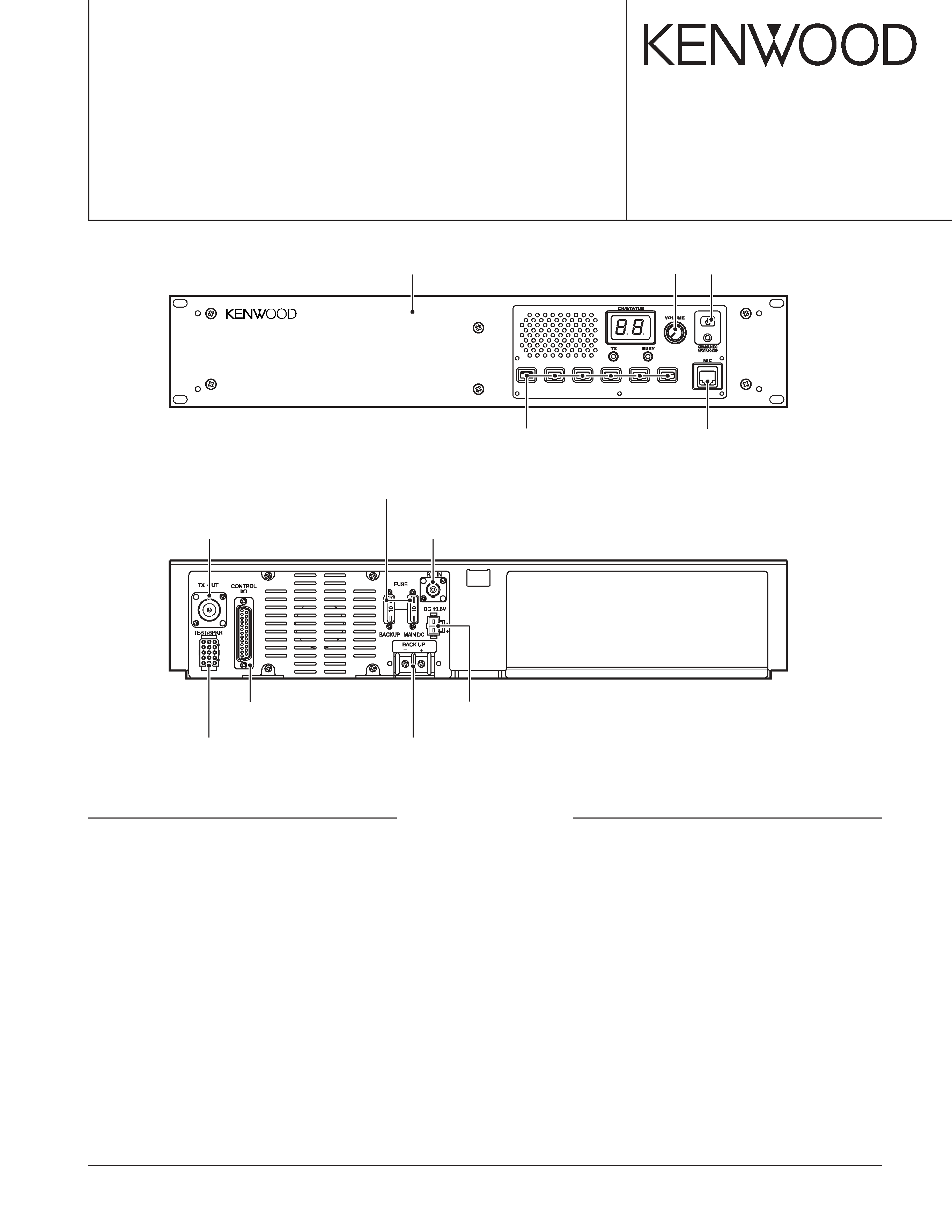
Front panel
(A62-0934-03)
Knob (DC source)
(K29-9106-04)
Key top
(K29-5460-02)
Knob (Volume)
(K29-5389-03)
Modular jack
(E08-0877-05)
Antenna cable (N)
(E30-7528-05)
Antenna cable (BNC)
(E30-3418-05)
TEST/SPKR connector assy
(E37-0913-05)
D-sub cable assy
(E37-0904-05)
DC backup terminal
(E70-0402-05)
DC cord (Ext DC in)
(E30-3414-05)
Fuse (Blade, 10A/32V)
(F06-1032-05) x 2
GENERAL ................................................................. 2
SYSTEM SET-UP ..................................................... 2
OPERATING FEATURES ......................................... 3
REALIGNMENT ........................................................ 4
INSTALLATION ........................................................ 5
MODIFICATION ....................................................... 8
DISASSEMBLY FOR REPAIR ................................ 10
CIRCUIT DESCRIPTION ......................................... 11
SEMICONDUCTOR DATA ..................................... 18
COMPONENTS DESCRIPTION ............................. 20
PARTS LIST ............................................................ 22
EXPLODED VIEW .................................................. 34
PACKING ................................................................ 36
ADJUSTMENT ....................................................... 37
CONTENTS
TERMINAL FUNCTION ......................................... 46
INTERCONNECTION DIAGRAM ........................... 50
PC BOARD
FINAL UNIT (X45-3742-71) ............................... 52
DISPLAY UNIT (X54-3330-21) .......................... 56
TX-RX UNIT (X57-6962-70) (A/2) ..................... 60
TX-RX UNIT (X57-6962-70) (B/2) ..................... 64
RX VCO UNIT (X58-4800-10) ........................... 68
TX VCO UNIT (X58-4810-10) ............................ 69
SCHEMATIC DIAGRAM ........................................ 70
BLOCK DIAGRAM .................................................. 83
KES-5 (EXTERNAL SPEAKER) .............................. 86
SPECIFICATIONS ................................................... 87
TKR-851
2
GENERAL / SYSTEM SET-UP
INTRODUCTION
SCOPE OF THIS MANUAL
This manual is intended for use by experienced techni-
cians familiar with similar types of commercial grade commu-
nications equipment. It contains all required service informa-
tion for the equipment and is current as of this publication
date. Changes which may occur after publication are covered
by either Service Bulletins or Manual Revisions, which are
issued as required.
ORDERING REPLACEMENT PARTS
When ordering replacement parts or equipment informa-
tion, the full part identification number should be included.
This applies to all parts : components, kits, and chassis. If the
part number is not known, include the chassis or kit number
of which it is a part and a sufficient description of the required
component, for proper identification.
PERSONAL SAFETY
The following precautions are recommended for personal
safety :
·DO NOT transmit until all RF connectors are secure and
any open connectors are properly terminated.
· SHUT OFF this equipment when near electrical blasting
caps or while in an explosive atmosphere.
· This equipment should be serviced by only qualified tech-
nicians.
SERVICE
This radio is designed for easy servicing. Refer to the
schematic diagrams, printed circuit board views, and align-
ment procedures contained in this manual.
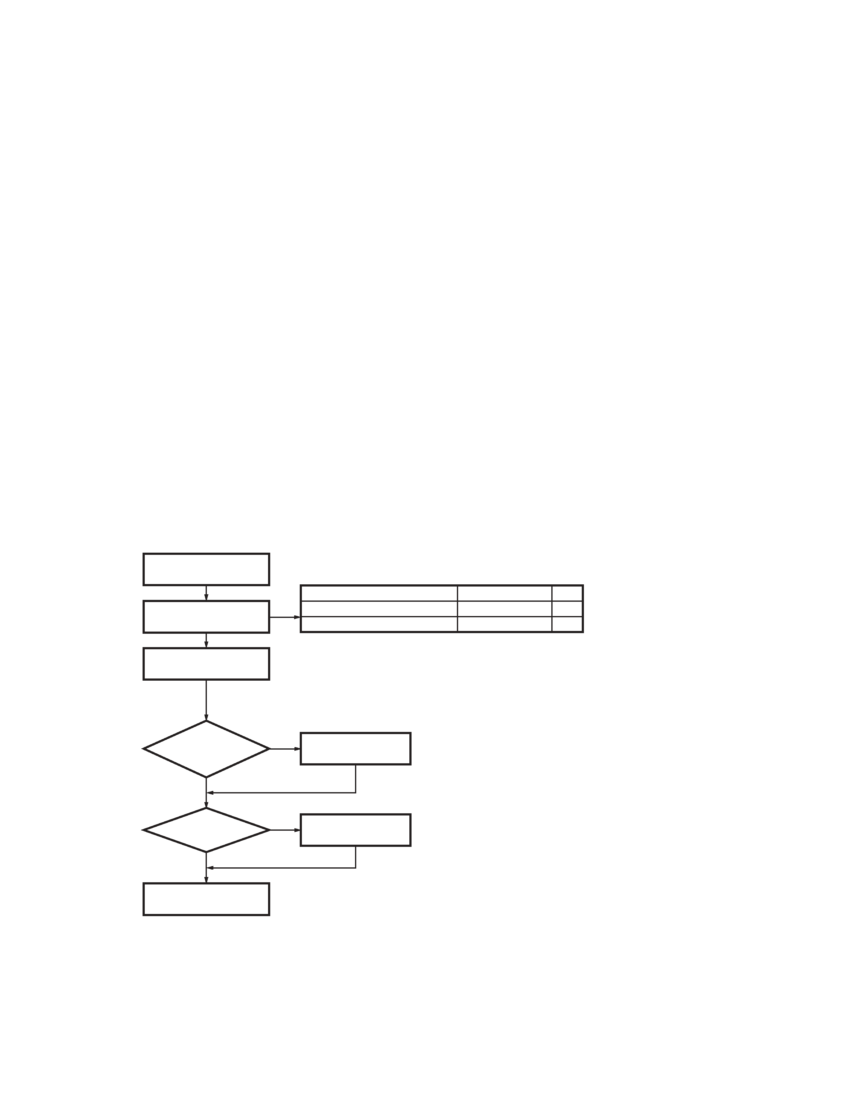
Merchandise
received
Choose the type
of transceiver
Installation in the
optional space
Frequency range (MHz)
TX/RX 440~470
TX/RX 450~480
RF power
25W
25W
Type
E
K
See page 4.
A personal computer (IBM PC or compatible), programming interface (KPG-46),
and programming software (KPG-91D) are required for programming.
See page 40.
The RX RF BPF (L2,L4,L5 on TX-RX unit A/2) must be aligned to obtain
the maximum sensitivity at a programmed frequency.
YES
NO
DC power
supply or
duplexer?
KES-4 or KES-5
installation
YES
NO
External speaker?
Repeater
programming & setup
Delivery
SYSTEM SET-UP
TKR-851
3
OPERATING FEATURES
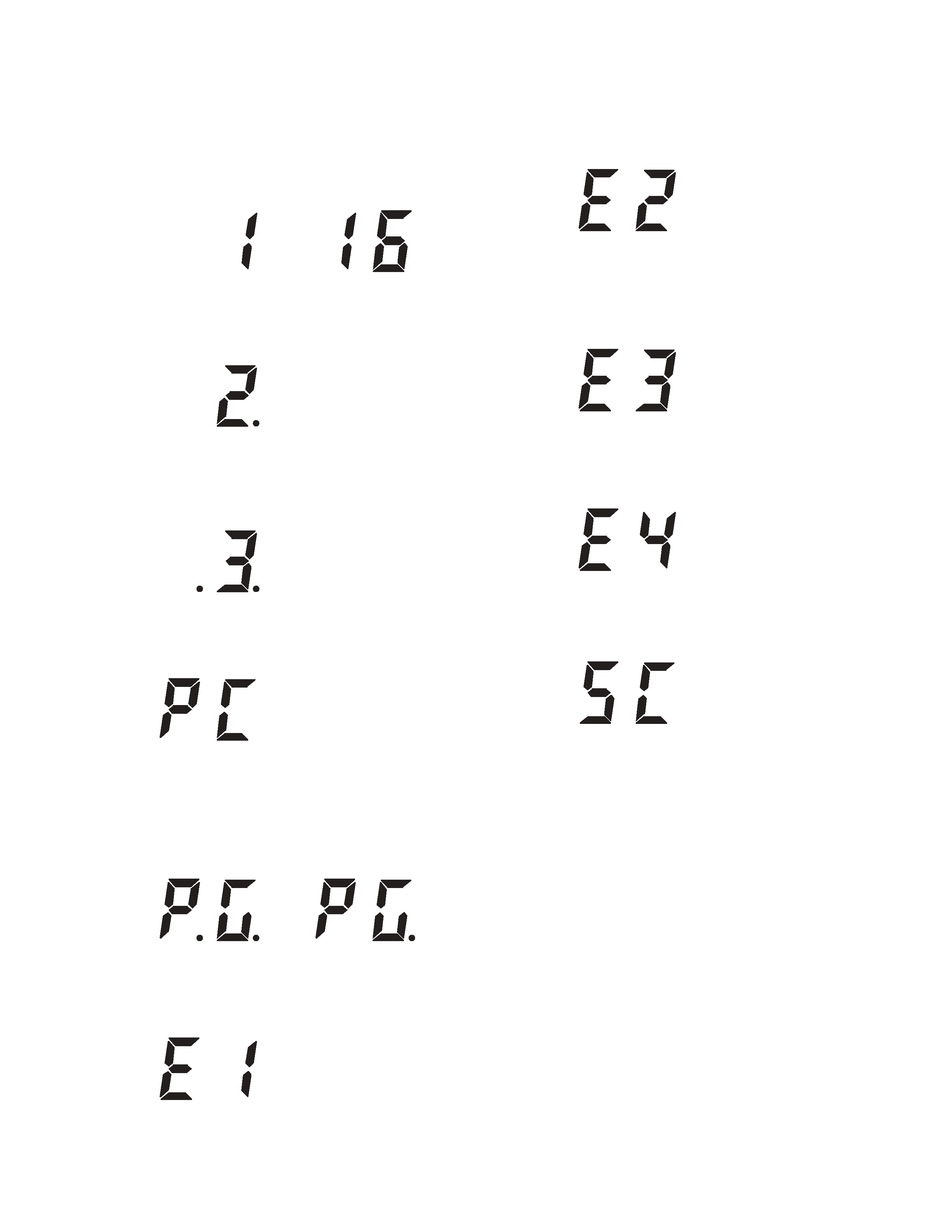
1. Two 7-segment LED displays
· Channel display (1~16) : While operating normally in user
mode.
· When the displayed channel is contained in scan se-
quence, the right side decimal point is displayed.
· When the displayed channel is the priority channel, the left
side decimal point is displayed.
· "PC" is displayed while in PC mode.
· "PG" is displayed while in firmware programming mode.
2 decimal points displayed = 115,200bps
1 decimal point displayed = 57,600bps
No decimal = 38,400bps
· "E1" is displayed when FPU data is not written.
· "E2" is displayed when the channel data is not written.
· "E3" is displayed when PLL is unlocked.
Receiver PLL unlocked = BUSY LED blinks.
Transmitter PLL unlocked = TX LED blinks.
· "E4" is displayed when PTT is attempted on a channel
number that has no frequency data programmed.
· "SC" is displayed while in scan mode.
TKR-851
4
1. Modes
3-3. KPG-46 Description (PC Programming Inter-
face Cable : Option)
The KPG-46 is required to interface the TKR-851 to the
computer. It has a circuit in its D-sub connector (25-pin) case
that converts the RS-232C logic level to the TTL level.
The KPG-46 connects the microphone connector of the
TKR-851 to the computer's RS-232C serial port.
3-4. Programming Software Description
The KPG-91D is the programming software for TKR-851
supplied on a CD-ROM. This software runs under Windows
98, ME, Windows 2000 or XP on an IBM-PC or compatible
machine.
The data can be input to or read from TKR-851 and edited
on the screen. The programmed or edited data can be
printed out. It is also possible to tune the transceiver.
3-5. Programming With IBM PC
Data can be programmed into the flash memory in RS-
232C format via the microphone connector.
User mode
PC mode
Firmware Programming mode
PC programming mode
PC test mode
PC tuning mode
Mode
Function
User mode
Use this mode for normal operation.
PC mode
Use this mode to make various settings by
means of the FPU through the RS-232C port.
PC programming
Use to read and write frequency data and
mode
other features to and from the repeater.
PC test mode
Use to check the repeater using the PC.
This feature is included in the FPU.
Firmware pro-
Use when changing the firmware program
gramming mode
of the flash memory.
2. How to Enter Each Mode
Mode
Operation
User mode
Power on.
PC mode
Received commands from PC.
Firmware Pro-
[PF1] key + Power on (one second).
gramming mode
3. PC Mode
3-1. Preface
The TKR-851 repeater is programmed by using a personal
computer, programming interface and KPG-91D software.
3-2. Connection Procedure
1. Connect the TKR-851 to the personal computer with the
interface cable.
2. When power is applied, the user mode is entered immedi-
ately. When the PC sends a command, the repeater en-
ters the PC mode and displays "PC" on the 7-segment
LED. When data is being transmitted to the PC from the
repeater, the TX LED flashes. The BUSY LED flashes
when data from the PC is being received by the repeater.
Note :
· The data stored in the personal computer must match the
model type, when it is written into the flash memory.
· Change the TKR-851 to PC mode, then attach the inter-
face cable.
REALIGNMENT
IBM-PC
KPG-46
KPG-91D
TKR-851
Fig. 1
4. Firmware Programming Mode
4-1. Preface
The TKR-851 uses flash memory to allow it to be easily
upgraded when new features are released in the future.
4-2. Connection Procedure
Connect the TKR-851 to the personal computer (IBM PC
or compatible) with the interface cable (KPG-46). (Connection
is the same as in the PC mode.)
Notes :
You can only program firmware from the 8-pin micro-
phone connector on the front panel. Using the 25-pin logic
interface on the rear panel will not work.

TKR-851
5
4-3. Programming
1. Start up the programming software (Fpro. exe).
2. Set the communications speed (normally, 115200 bps)
and communications port in the configuration item.
3. Set the firmware to be updated by file name item.
4. Turn the TKR-851 power on with the [PF1] key held down.
Hold the key down for one second until the 7-segment
display changes to "P.G.". When "P.G." appears, release
your finger from the key.
5. Check the connection between the TKR-851 and the per-
sonal computer, and make sure that the TKR-851 is in the
program mode.
6. Press write button in the window. A window opens on
the display to indicate progress of writing.
7. If writing ends successfully, the TX LED on the TKR-851
lights.
8. If you want to continue programming other TKR-851s, re-
peat steps 3 to 6.
Notes :
This mode cannot entered if the firmware program mode
is set to disable in the programming software (KPG-91D).
4-4. Function
If you press the [PF1] key (front panel), both decimal point
on the 7-segment display will disappear. The writing speed is
38400 bps (low-speed mode). If you press the [PF1] key
again, the right hand decimal points will light. The writing
speed is 57600 bps (middle-speed mode).
Note :
Normally, write in the high-speed mode (115200 bps).
REALIGNMENT / INSTALLATION
INSTALLATION
1. External Power Supply Connection
(Rear Connectors)
This unit has two external power supply connectors : Main
DC and Backup.
If an external DC power supply is connected to the main
DC connector and a backup battery is connected to the
Backup connector at the same time, the DC power supply
switches to the battery automatically if power failure occurs.
Therefore, the operation of the repeater can be continued.
If the battery is used, but both the battery and power sup-
ply need not be connected (if an external switch is used or if
only a solar battery is used), connect it to the Backup connec-
tor, not the Main DC connector. Current consumption can be
reduced by approx. 120mA because the relay is not used.
If it is installed when the temperature at the repeater site
is below freezing, check whether the switch (relay) works
properly after installation.
2. Voice Scrambler
It operates only during base operation. The voice is not
scrambled when it is repeated.
2-1. Modification
1) Remove R742 and R653 on the TX-RX unit (B/2) : control
section.
2-2. Connection
1) The functions of pins of CN601 on the TX-RX unit (B/2) :
control section are shown in the figure.
2) Join the CN601 connector to the voice scrambler board via
the E37-0808-05 connector cable.
When the operation is checked in PC test mode after the
modification, and the maximum deviation is adjusted, the
voice from the local microphone is not modulated. In this
case, remove the CN601 12-pin (PTO) cable and connect it to
the land of the display unit (X54-333) from the voice scram-
bler. The voice from the local microphone can be modulated
in PC test mode.