VHF FM REPEATER
SERVICE MANUAL
GENERAL ................................................................ 2
SYSTEM SET-UP .................................................... 2
INSTALLATION ....................................................... 3
OPERATING FEATURES ........................................ 4
REALIGNMENT ..................................................... 13
APPLICATION NOTE ............................................ 15
DISASSEMBLY FOR REPAIR ............................... 24
CIRCUIT DESCRIPTION ........................................ 26
SEMICONDUCTOR DATA .................................... 43
COMPONENTS DESCRIPTION ............................ 46
PARTS LIST ........................................................... 48
EXPLODED VIEW .................................................. 61
PACKING ............................................................... 63
CONTENTS
TERMINAL FUNCTION ......................................... 64
ADJUSTMENT ...................................................... 69
PC BOARD
CONTROL UNIT (X53-3882-71) ...................... 81
TX UNIT (X56-3072-70) ................................... 91
RX UNIT (X55-3050-11) ................................. 103
SCHEMATIC DIAGRAM ...................................... 109
BLOCK DIAGRAM ............................................... 121
LEVEL DIAGRAM ................................................ 123
INTERCONNECTION DIAGRAM ........................ 125
KES-4 (EXTERNAL SPEAKER) ........................... 127
KPG-46 (PROGRAMMING INTERFACE CABLE) ..... 128
SPECIFICATIONS ............................... BACK COVER
TKR-740
© 2002-12 PRINTED IN JAPAN
B51-8642-00 (S) 272
LED
(B30-2197-05)
PUSH KNOB (TEST)
(K29-3002-14)
MODULAR JACK
(E08-0876-05)
LED
(B30-2198-05)
LED
(B30-0864-05)
Panel (Front)
(A62-0726-03)
LED ASSY
(LA301DB)
KNOB (VOL)
(K29-4539-04)
E VERSION
TKR-740
2
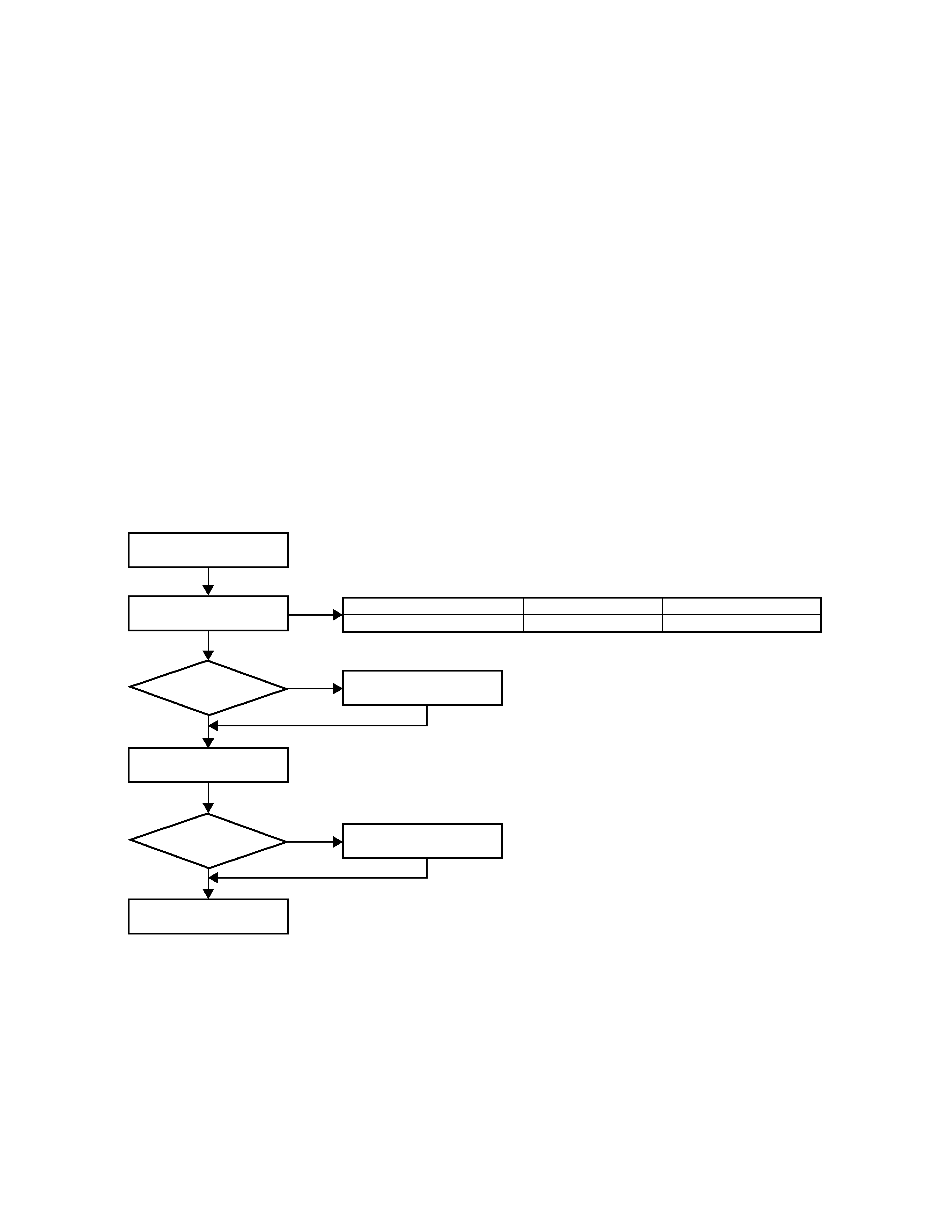
Merchandise
received
Choose the type
of transceiver
External RX Filter
External speaker
Repeater
programming & setup
Delivery
KES-4
installation
RX modification
See page 3
See page 14
A personal computer (IBM PC compatible), programming cable (KPG-46),
and programming disk (KPG-47D) are required for programming.
Yes
Yes
No
No
Type
RF power
5W to 25W
Frequency range (MHz)
158-174 (RX)/146-174 (TX)
TKR-740 E
GENERAL / SYSTEM SET-UP
INTRODUCTION
SCOPE OF THIS MANUAL
This manual is intended for use by experienced technicians
familiar with similar types of commercial grade
communications equipment. It contains all required service
information for the equipment and is current as of the
publication date. Changes which may occur after publication
are covered by either Service Bulletins or Manual Revisions.
These are issued as required.
ORDERING REPLACEMENT PARTS
When ordering replacement parts or equipment information,
the full part identification number should be included. This
applies to all parts, components, kits, or chassis. If the part
number is not known, include the chassis or kit number of
which it is a part, and a sufficient description of the required
component for proper identification.
PERSONNEL SAFETY
The following precautions are recommended for personnel
safety:
DO NOT transmit until you verify that all RF connectors are
secure and any open connectors are properly terminated.
SHUT OFF and DO NOT operate this equipment near
electrical blasting caps or in an explosive atmosphere.
This equipment should be serviced by a qualified technician
only.
SERVICE
This radio is designed for easy servicing. Refer to the
schematic diagrams, printed circuit board views, and alignment
procedures contained within.
SYSTEM SET-UP
TKR-740
3
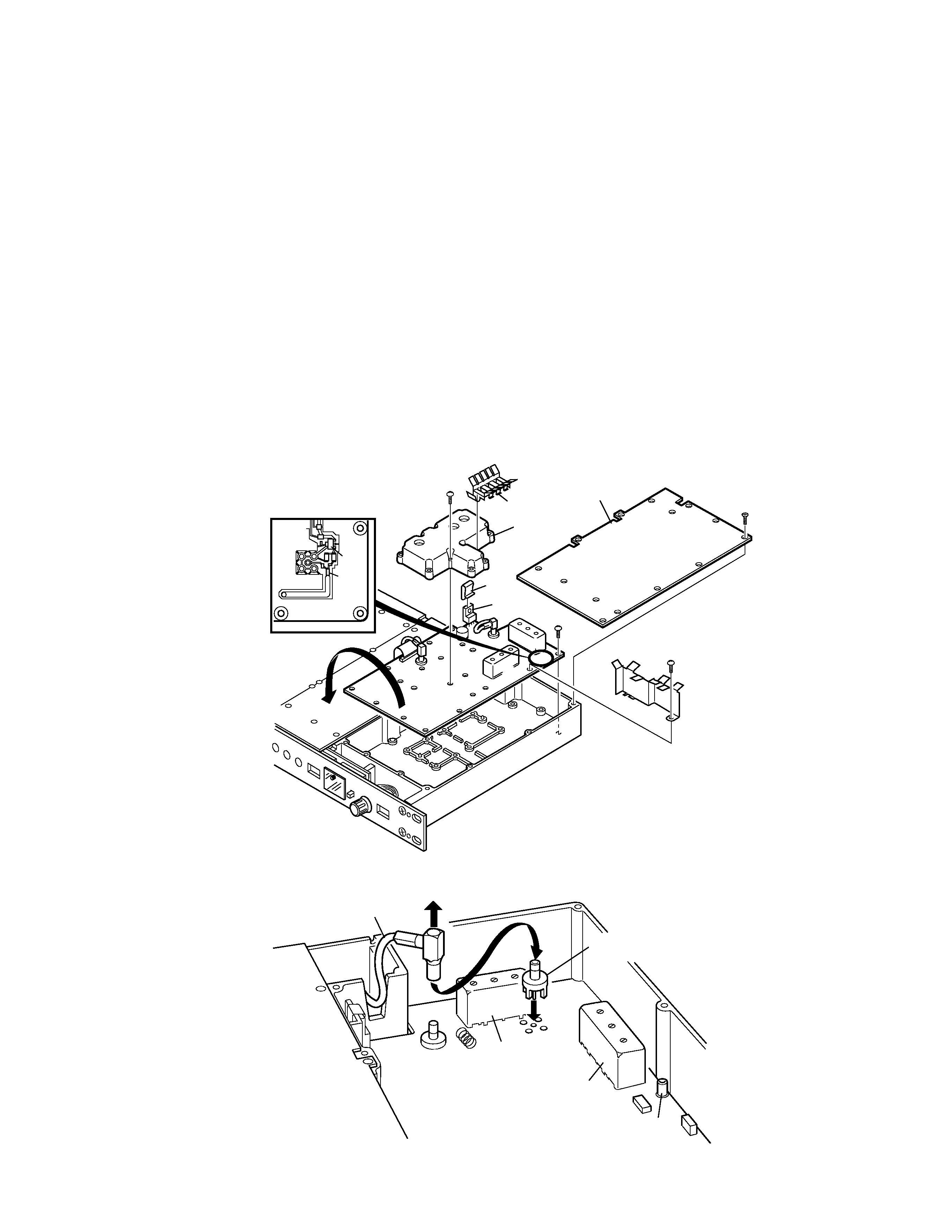
INSTALLATION
RX MODIFICATION FOR EXTERNAL
PRESELECTOR FILTER
This model may be modified to use an external pre-selector
filter.
1 Remove the RX cover panel.
2 Remove the flat clip spring from IC4 and L16
3 Remove the 11 screws from the RX unit and the 10 screws
from the shield case.
4 Remove the jumper (R179) from the reverse side of the RX
unit.
5 Insert an SMB receptacle (E04-0409-05) at CN10. Solder
the 5 leads in place.
6 Replace the screws on the RX unit and shield case, and the
flat clip spring on IC4 and L16.
7 Move the RX IN signal cable (from the back panel) from
CN1 to CN10.
8 Connect a tracking generator signal to RX IN, then use a
spectrum analyzer to read the output at CN2 while adjusting
L16 for the proper response.
9 Next, adjust IF , squelch , and RSSI.
0 Replace the RX cover panel.
RX
UNIT
PANEL
screw x14
screw x10
screw x11
screw
flat clip spring
Foil side view
shield case
flat clip
spring
IC4
L3
L16
RX UNIT
(X55-305)
IC17
R179
(0)
RX.IN Signal cable
L16
L3
CN1
CN10
CN2
SMB Receptacle
(E04-0409-05)
TKR-740
4
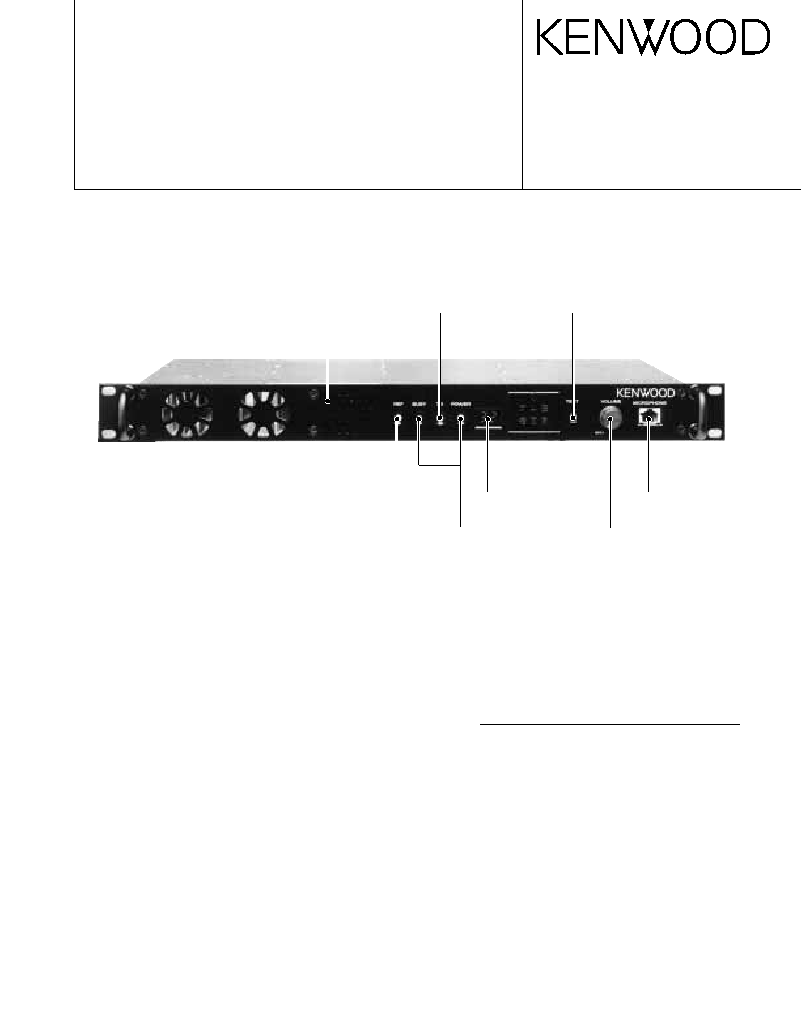
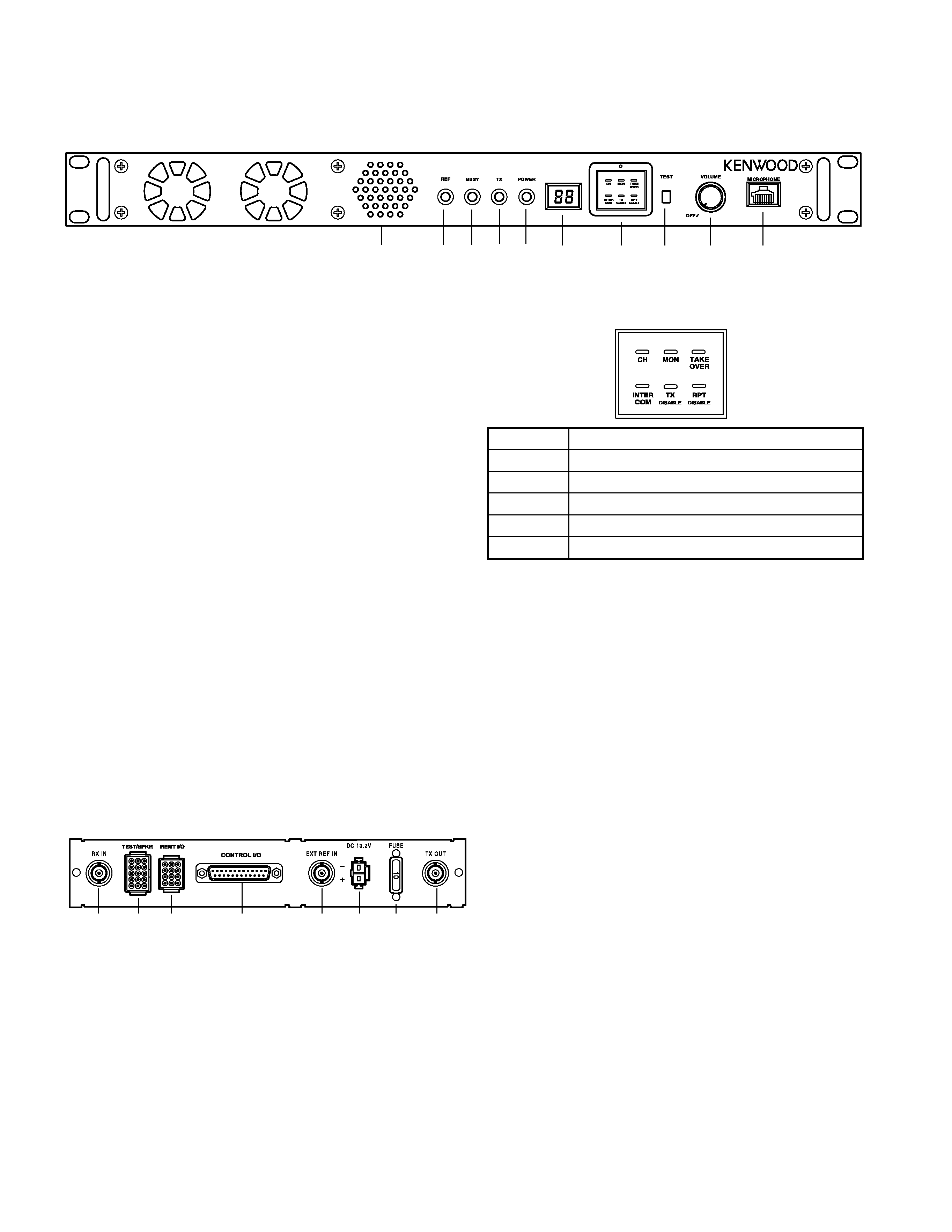
OPERATING FEATURES
q
q
q
q
q Speaker
w
w
w
w
w REF (reference) indicator
Lights red when using an external reference
oscillator. Lights green when using the internal
oscillator.
e
e
e
e
e BUSY indicator
Lights green when receiving. Flashes when
receiving data from the KPG-47D or when the
receiver PLL is unlocked.
r
r
r
r
r TX (transmit) indicator
Lights red when transmitting. Flashes when
transmitting data to the KPG-47D (during
programming) or when the transmit PLL is
unlocked.
t
t
t
t
t POWER indicator
Lights green when DC power is applied to the
TKR-740.
y
y
y
y
y Display
Two 7-segment digits display the channel
number or status.
2. Rear Panel
q
q
q
q
q RX IN jack
Connect an RX antenna or a duplexer to this
BNC receptacle.
w
w
w
w
w TEST/SPKR jack
Test input/output jack. Connect an external
speaker to this jack.
e
e
e
e
e REMT I/O jack
Connect an external remote controller to this
jack.
r
r
r
r
r CONTROL I/O jack
Connect an external programming device or an
external repeater controller to this
DB-25 interface port.
t
t
t
t
t EXT REF IN jack
Connect a high-stability external frequency
reference oscillator (10MHz, -10dBm or higher)
to this BNC receptacle (optional).
y
y
y
y
y DC 13.2V jack
Connect a 13.2 V DC power supply to this jack.
u
u
u
u
u FUSE
Insert a 10 A blade fuse into this fuse holder.
i
i
i
i
i TX OUT jack
Connect a TX antenna or a duplexer to this
BNC receptacle.
1. Front Panel
w
w
w
w
w
e
e
e
e
e
r
r
r
r
r
t
t
t
t
t
y
y
y
y
y
u
u
u
u
u
q
q
q
q
q
i
i
i
i
i
q
q
q
q
q
w
w
w
w
w e
e
e
e
e r
r
r
r
r t
t
t
t
t
y
y
y
y
y
u
u
u
u
u
i
i
i
i
i
o
o
o
o
o
!0
!0
!0
!0
!0
u
u
u
u
u Programmable Function keys
Press these keys to activate their
programmable functions.
i
i
i
i
i TEST switch
Press to transmit an unmodulated signal with
no local microphone connected. If an external
modulation signal source is connected to the
CONTROL I/O jack, the RF signal is modulated
with this signal source.
o
o
o
o
o VOLUME control
Turn clockwise until a click sounds, to unmute
the volume. Rotate to adjust the volume. Turn
counterclockwise fully to mute the volume.
!0
!0
!0
!0
!0 MICROPHONE jack
Connect a microphone to 8-pin modular jack.
PF1 PF2 PF3
PF4 PF5 PF6
PF 1 Key
Default: CH (CH UP)
PF 2 Key
Default: MON (MONITOR ON/OFF)
PF 3 Key
Default: TAKE OVER (TAKE OVER ON/OFF)
PF 4 Key
Default: INTERCOM (INTERCOM ON/OFF)
PF 5 Key
Default: TX DISABLE (TX Disable/Enable)
PF 6 Key
Default: RPT DISABLE (Repeat Disable/Enable)
TKR-740
5
OPERATING FEATURES
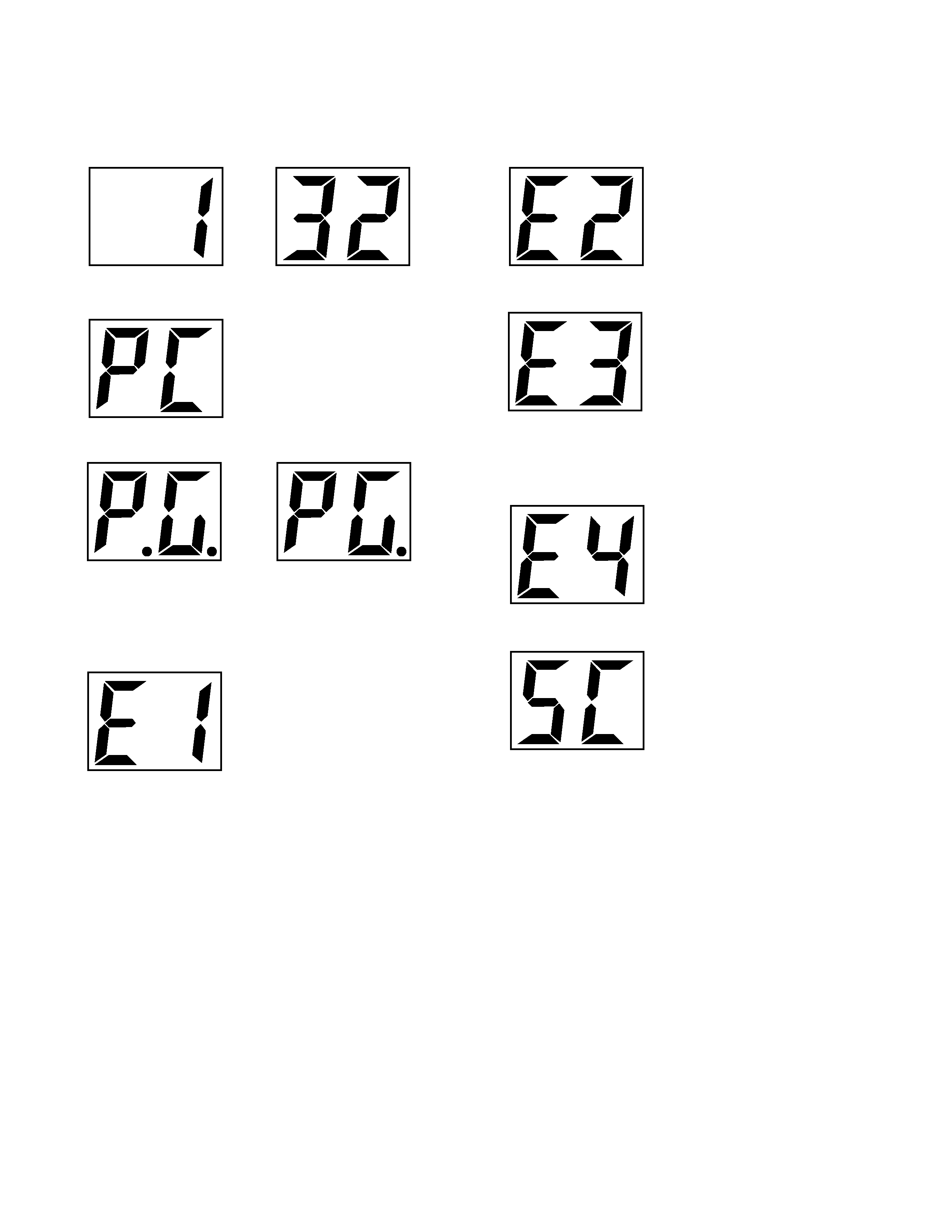
3. Two 7-segment LED Displays
Channel display (1-32): while operating normally in User
Mode
"PC" displayed while in PC Mode.
"PG" displayed while in Firmware Programming Mode
2 decimal points displayed = 115,200 bps
1 decimal point displayed = 57,600 bps
No decimal = 38,400 bps
"E1" displayed when FPU data is not written.
"E2" displayed when the channel data is not written.
"E3" displayed when PLL is unlocked .
Receiver PLL unlocked = flashing BUSY LED.
Tansmitter PLL unlocked = flashing TX LED.
Internal 19.2MHz reference unlocked = flashing decimal point
.
"E4" displayed when PTT is attempted on a channel number
that has no frequency data programmed.
"SC" displayed while in scan mode
when the displayed channel is contained in scan sequence,
the right side decimal point is displayed.
When the displayed cahnnel is the priority channel, the left
side decimal point is displayed.