© 2001-6 PRINTED IN JAPAN
B51-8439-10 (N) 1233
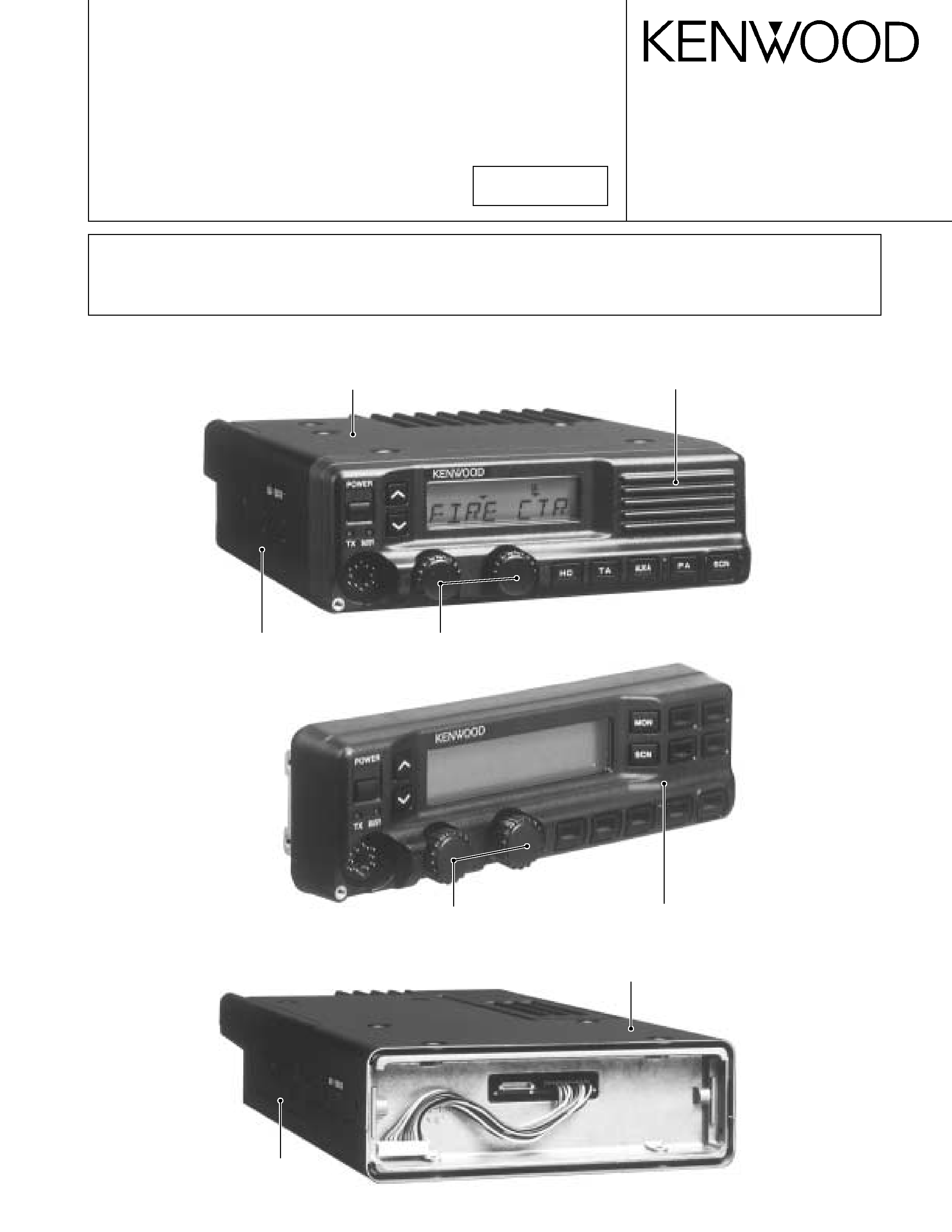
UHF FM TRANSCEIVER
TK-890/(B)
TK-890H(B)
SERVICE MANUAL
Cabinet (Upper)
(A01-2161-02)
Cabinet (Upper)
(A01-2163-01)
Panel assy
(A62-0606-13)
Panel assy
(A62-0607-13)
Cabinet (Lower)
(A01-2164-01)
Knob
(K29-4664-04) x 2
Cabinet (Lower)
(A01-2162-02)
Knob
(K29-4664-04) x 2
KCH-11
TK-890H(B)
REVISED
TK-890 or TK-890(B) with KCH-10
This service manual applies to products with 30300001 or subsequent serial numbers. (KCH-10 and KCH-11 are applicable to
the productions June 2001 and after.)
In terms of the products with the serial numbers earier than 30300001, refer to the TK-890/(B)/H(B) service manual as per
part No. B51-8439-00 and the TK-890(B) service manual as per part No. B51-8457-00.

2
TK-890/(B)/H(B)
CONTENTS / GENERAL
GENERAL ......................................................................................................................... 2
SYSTEM SET-UP ............................................................................................................. 4
OPERATING FEATURES ................................................................................................. 5
INSTALLATION .............................................................................................................. 16
DISASSEMBLY FOR REPAIR ........................................................................................ 22
CIRCUIT DESCRIPTION ................................................................................................. 26
SEMICONDUCTOR DATA ............................................................................................. 32
DESCRIPTION OF COMPONENTS ............................................................................... 36
PARTS LIST .................................................................................................................... 39
EXPLODED VIEW .......................................................................................................... 58
PACKING ........................................................................................................................ 62
ADJUSTMENT ............................................................................................................... 66
TERMINAL FUNCTION ................................................................................................. 76
WIRING .......................................................................................................................... 79
PC BOARD VIEWS / CIRCUIT DIAGRAMS
DISPLAY UNIT (X54-3190-20) : KCH-10 .................................................................. 81
DISPLAY UNIT (X54-3200-20) : KCH-11 .................................................................. 83
CONTROL UNIT (X57-5620-XX) (B/3) ..................................................................... 89
FINAL UNIT (X57-5620-XX) (C/3) : TK-890/(B) ....................................................... 99
TX-RX UNIT (X57-5620-XX) (A/3) ......................................................................... 103
FINAL UNIT (X45-3570-10) : TK-890H(B) .............................................................. 115
BLOCK DIAGRAM ........................................................................................................ 119
SPECIFICATIONS ......................................................................................................... 121
GENERAL
INTRODUCTION
SCOPE OF THIS MANUAL
This manual is intended for use by experienced techni-
cians familiar with similar types of commercial grade com-
munications equipment. It contains all required service in-
formation for the equipment and is current as of this publica-
tion date. Changes which may occur after publication are
covered by either Service Bulletins or Manual Revisions,
which are issued as required.
ORDERING REPLACEMENT PARTS
When ordering replacement parts or equipment informa-
tion, the full part identification number should be included.
This applies to all parts : components, kits, and chassis. If
the part number is not known, include the chassis or kit
number of which it is a part and a sufficient description of
the required component, for proper identification.
PERSONNEL SAFETY
The following precautions are recommended for person-
nel safety :
· DO NOT transmit if someone is within two feet (0.6
meter) of the antenna.
· DO NOT transmit until all RF connectors are secure and
any open connectors are properly terminated.
· SHUT OFF this equipment when near electrical blasting
caps or while in an explosive atmosphere.
· All equipment should be properly grounded before
power-up for safe operation.
· This equipment should be serviced by only qualified tech-
nicians.

3
TK-890/(B)/H(B)
PRE-INSTALLATION CONSIDERATIONS
1. UNPACKING
Unpack the radio from its shipping container and check
for accessory items. If any item is missing, please contact
KENWOOD immediately.
2. LICENSING REQUIREMENTS
Federal regulations require a station license for each ra-
dio installation (mobile or base) be obtained by the equip-
ment owner. The licensee is responsible for ensuring trans-
mitter power, frequency, and deviation are within the limits
permitted by the station license.
Transmitter adjustments may be performed only by a li-
censed technician holding an FCC first, second or general
class commercial radiotelephone operator's license. There
is no license required to install or operate the radio.
3. PRE-INSTALLATION CHECKOUT
3-1. Introduction
Each radio is adjusted and tested before shipment. How-
ever, it is recommended that receiver and transmitter opera-
tion be checked for proper operation before installation.
3-2. Testing
The radio should be tested complete with all cabling and
accessories as they will be connected in the final installa-
tion. Transmitter frequency, deviation, and power output
should be checked, as should receiver sensitivity, squelch
operation, and audio output. QT equipment operation
should be verified.
4. PLANNING THE INSTALLATION
4-1. General
Inspect the vehicle and determine how and where the
radio antenna and accessories will be mounted.
Plan cable runs for protection against pinching or crush-
ing wiring, and radio installation to prevent overheating.
4-2. Antenna
The favored location for an antenna is in the center of a
large, flat conductive area, usually at the roof center. The
trunk lid is preferred, bond the trunk lid and vehicle chassis
using ground straps to ensure the lid is at chassis ground.
4-3. Radio
The universal mount bracket allows the radio to be
mounted in a variety of ways. Be sure the mounting surface
is adequate to support the radio's weight. Allow sufficient
space around the radio for air cooling. Position the radio
close enough to the vehicle operator to permit easy access
to the controls when driving.
4-4. DC Power and wiring
1. This radio may be installed in negative ground electrical
systems only. Reverse polarity will cause the cable fuse
to blow. Check the vehicle ground polarity before installa-
tion to prevent wasted time and effort.
2. Connect the positive power lead directly to the vehicle
battery positive terminal. Connecting the Positive lead to
any other positive voltage source in the vehicle is not rec-
ommended.
3. The cable provided with the radio is sufficient to handle
the maximum radio current demand. If the cable must be
extended, be sure the additional wire is sufficient for the
current to be carried and length of the added lead.
5. INSTALLATION PLANNING CONTROL STATIONS
5-1. Antenna system
Control station. The antenna system selection depends
on many factors and is beyond the scope of this manual.
Your KENWOOD dealer can help you select an antenna sys-
tem that will best serve your particular needs.
5-2. Radio location
Select a convenient location for your control station radio
which is as close as practical to the antenna cable entry
point. Secondly, use your system's power supply (which
supplies the voltage and current required for your system).
Make sure sufficient air can flow around the radio and
power supply to allow adequate cooling.
SERVICE
This radio is designed for easy servicing. Refer to the
schematic diagrams, printed circuit board views, and align-
ment procedures contained in this manual.
GENERAL
4
TK-890/(B)/H(B)
Before Reading About System Set-up
The TK-890(B)/H(B) is a transceiver main unit (without a
panel or speaker) that you complete by adding options.
The options are classified into three types according to
operation and function.
1. Install the front panel kit (controller) directly on a radio to
operate it. (Form : Radio + KCH-10/11)
2. Remotely control one radio with one controller. (Form
: Radio + KRK-5 + KCH-10/11 + KCT-22M/M2/M3)
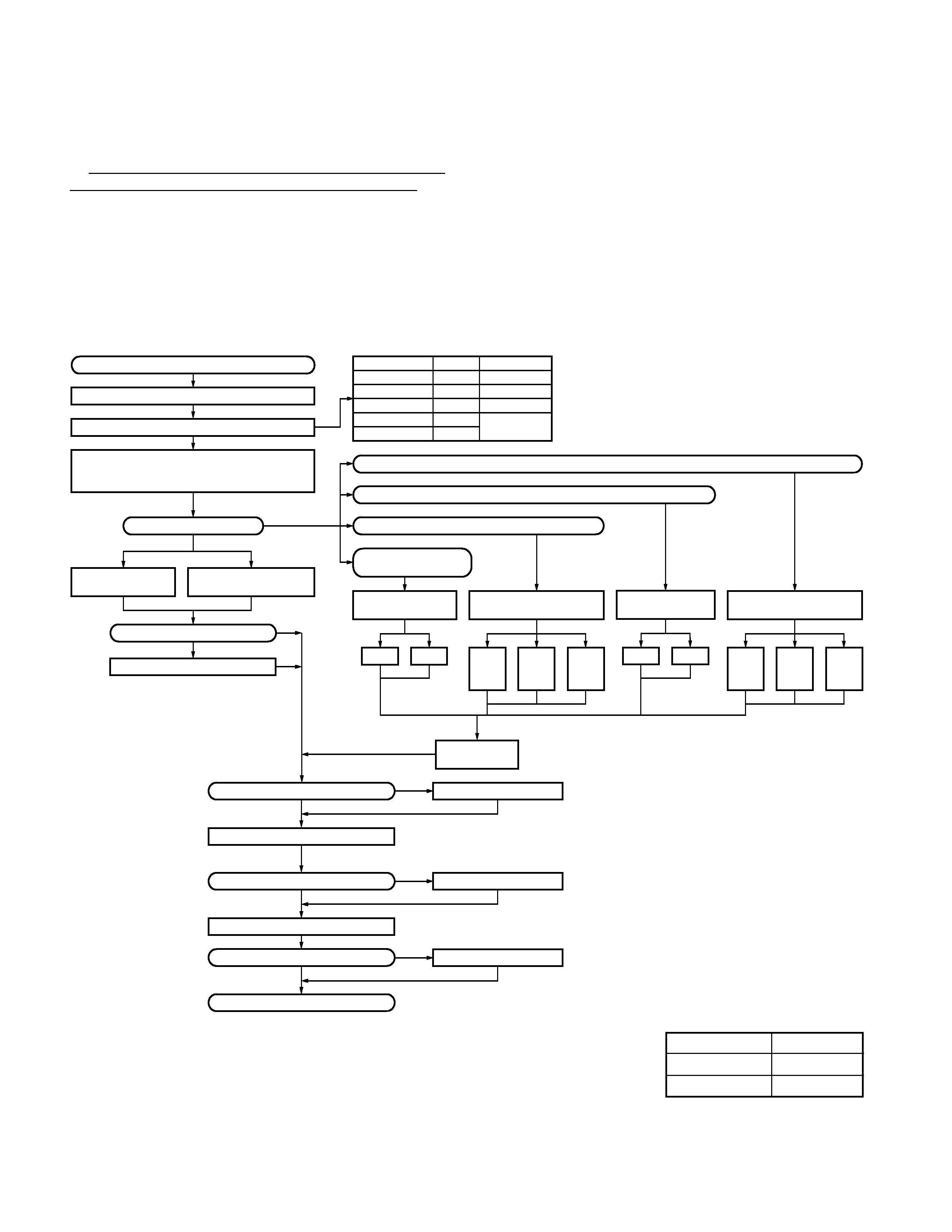
SYSTEM SET-UP
Merchandise received
License and frequency allocated by FCC
Choose the type of transceiver
TK-890/(B), TK-890H(B) (Radio 1)
TK-890(B) or TK-890H(B) is complete by combining
options with only the transceiver body (without panel)
Are you using the remote kit?
KCH-10 (Basic model)
Front panel kit
KCH-11 (Full featured
model) Front panel kit
Supplied accessory knob
Are you using one radio with two controllers?
Are you using one radio
with one controller?
Are you using two radios with one controller?
Are you using two radios with two controllers?
TK-890 : Contain (KCH-10)
Are you using the printed keytops?
KRK-5
Single control head kit
KRK-7DB
Dual band remote kit
KRK-6DH
Dual control head kit
KCH-10
KCH-11
KCH-10
KCH-11
KCH-10
+
KCH-10
KCH-10
+
KCH-11
KCH-11
+
KCH-11
or
or
or
or
KCT-22M/M2/M3
Control cable
YES
YES
*See Remote
kit service
manual
NO
NO
See
page 16
See page 16
See page 16
YES
KRK-8DBH
Dual band dual control head kit
KCH-10
+
KCH-10
KCH-10
+
KCH-11
KCH-11
+
KCH-11
or
or
YES
YES
Frequency range
450~490MHz
450~470MHz
YES
*See Remote kit
service manual
Are you using the voice scrambler?
Transceiver programming (option)
Are you using the external speaker?
KCT-23 (DC cable)
Are you using the ignition sense cable?
Delivery
Modified of control unit
YES
NO
NO
NO
KES-4 (EXT. SP)
YES
KCT-18
YES
See page 18
See page 18
See page 17
See page 13
A personal computer (IBM PC or compatible), programming interface (KPG-43),
and programming software (KPG-44D) are required for programming.
(The frequency and signalling data are programmed for the transceiver.)
See Installation manual
KCT-23 M,M3 : TK-890/(B), KCT-23 M2,M4 : TK-890H(B)
RF power
40W
100W
470~480MHz
75W
TK-890/(B) F1
480~512MHz
40W
TK-890(B) F2
403~430MHz
40W
TK-890(B) F3
TK-890H(B) F1
Type
3. Remotely control one radio with two controllers. (Form
: Radio + KRK-6DH + KCH-10/11 (two) + KCT-22M/M2/
M3 (two))
4. Remotely control two radios with one controller. (Form
: Radios (two) + KRK-7DB + KCH-10/11 + KCT-22M/M2/
M3)
5. Remotely control two radios with two controllers. (Form
: Radio (two) + KRK-8DBH + KCH-10/11 (two) + KCT-
22M/M2/M3 (two))
*Service manual parts No. list
Model
Parts No.
KRK-5/6DH
B51-8445-00
KRK-7DB/8DBH
B51-8452-00
5
TK-890/(B)/H(B)
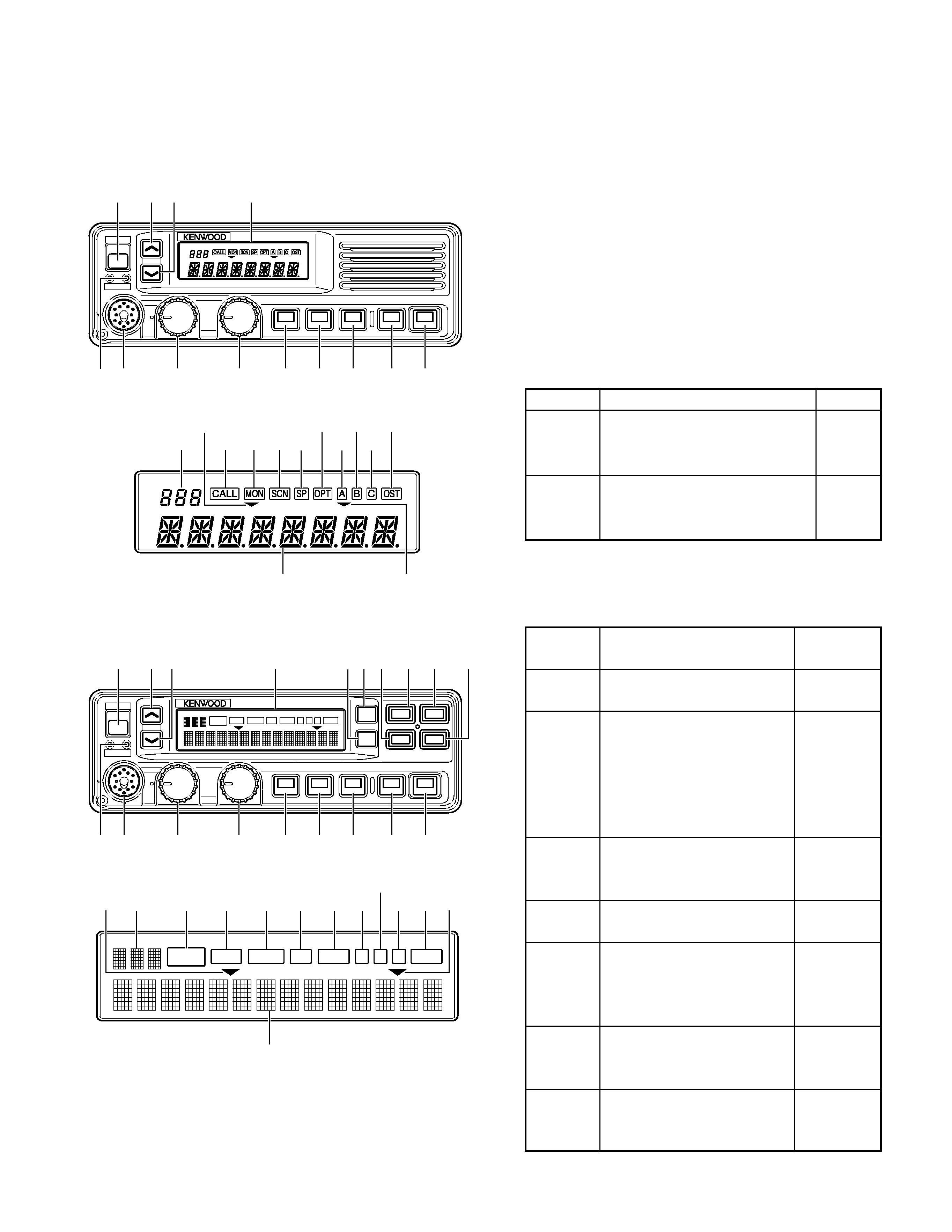
1. Controls and Functions
1-1. Basic Function Panel
(1) POWER Switch
Press to turn the power ON and OFF.
(2) TX/BUSY Indicator
The TX Indicator (Red LED) shows that you are transmit-
ting.
The BUSY Indicator (Green LED) shows that the channel
is in use.
(3) Microphone Connector
(4) Volume Knob
To increase the volume level, turn clockwise (CW).
To decrease the volume level, turn counterclockwise
(CCW).
(5) UP/DOWN Knob
The function of this Knob can be programmed by the
FPU.
Function
Description
Note
Channel
Channel selector.
Default
UP/DOWN
To increase the channel, turn CW.
setting.
To decrease the channel, turn CCW.
Group
Group selector.
UP/DOWN
To increase the group, turn CW.
To decrease the group, turn CCW.
(6) GR UP Key, (7) GR DW Key, (8) MON Key, (9) SCN Key,
(10)~(18) PF1-9 Key
The function of these Keys can be programmed by the
FPU.
Function
Description
Note
[ ] : Key top name
No
No function.
Default setting
Function
of PF1~9.
Monitor
If [MON] is pressed once while
Default setting
[MON]
the RADIO is waiting for reception,
of MON. (Full
all signalling* squelch is canceled.
function panel)
If [MON] is held down for 2 seconds,
all singalling;
noise squelch is canceled and the
QT/DQT &
audio is unmuted.
2 TONE/DTMF
Scan
Start and stop the scanning
Default setting
[SCN]
sequence.
of SCN. (Full
function panel)
Public
The RADIO works as a PUBLIC
Address [PA]
ADDRESS amplifier.
Horn Alert
When the RADIO receives a
[HA]
the optional signalling calls that
are assigned to the channel, the
HA relay turns on.
Talk Around
Use this function to communicate
[TA]
with other operators directry,
without using a repeater.
Intercom
Use this function to communicate
Dual HEAD
[IC]
between the HEAD1 and HEAD2
configuration
operator without transmitting.
only.
OPERATING FEATURES
GRP
VOL
CH
POWER
TX BUSY
(1)
(2) (3)
(4)
(5)
(10)
(11)
(12)
(13)
(14)
(19)
(7)
(6)
(20)
(29)
(32)
(30)
(31)
(21) (22)(23)
(24)
(25)
(26)
(27)
(28)
1-2. Full Function Panel
GRP
POWER
TX
VOL
CH
BUSY
SCAN
OPT
OST
A
B
C
MON
CALL
SP
MON
SCN
(1)
(2) (3)
(4)
(5)
(10)
(11)
(12)
(13)
(14)
(6) (7)
(19)
(9) (8)(17) (15) (16)
(18)
SCAN
OPT
OST
A
B
C
MON
CALL
SP
(29) (31)
(20)
(21)
(22)
(23)
(24) (25)
(26)
(27) (28)(30)
(32)