© 2000-12
B51-8541-10 (N) 610
TK-868HG
SERVICE MANUAL /
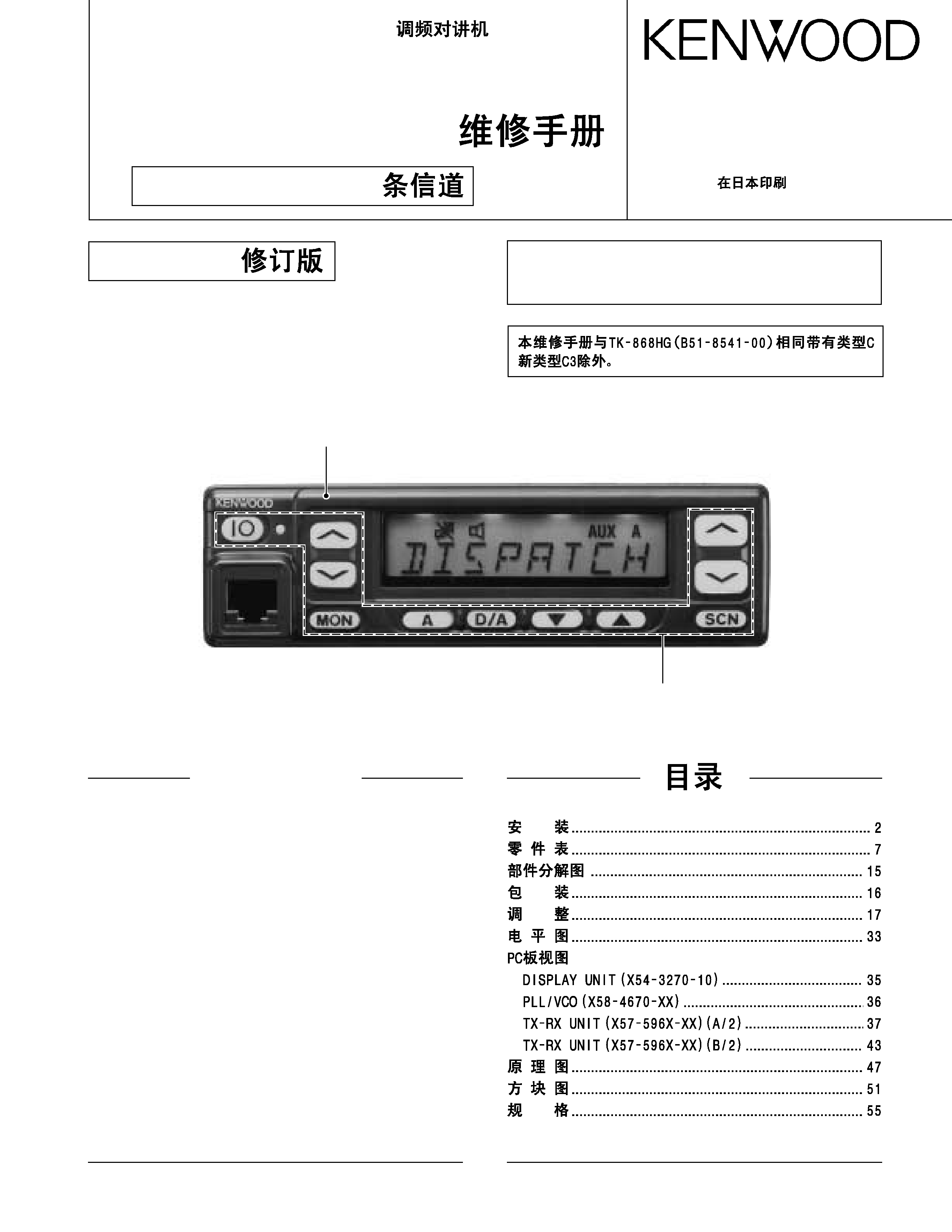
Panel assy
(A62-0642-03)
Key top
(K29-5343-02)
INSTALLATION ........................................................ 2
PARTS LIST .............................................................. 7
EXPLODED VIEW .................................................. 15
PACKING ................................................................ 16
ADJUSTMENT ....................................................... 17
LEVEL DIAGRAM ................................................... 33
PC BOARD VIEWS
DISPLAY UNIT (X54-3270-10) .......................... 35
PLL/VCO (X58-4670-XX) .................................. 36
TX-RX UNIT (X57-596X-XX) (A/2) ................... 37
TX-RX UNIT (X57-596X-XX) (B/2) ................... 43
SCHEMATIC DIAGRAM ........................................ 47
BLOCK DIAGRAM .................................................. 51
SPECIFICATIONS ................................................... 54
128 channels / 128
CONTENTS
REVISED /
The service manual is the same as the C market, TK-
868HG (B51-8541-00) service manual with the exception
of the new C3 market.
UHF FM TRANSCEIVER / UHF
2
TK-868HG
INSTALLATION /
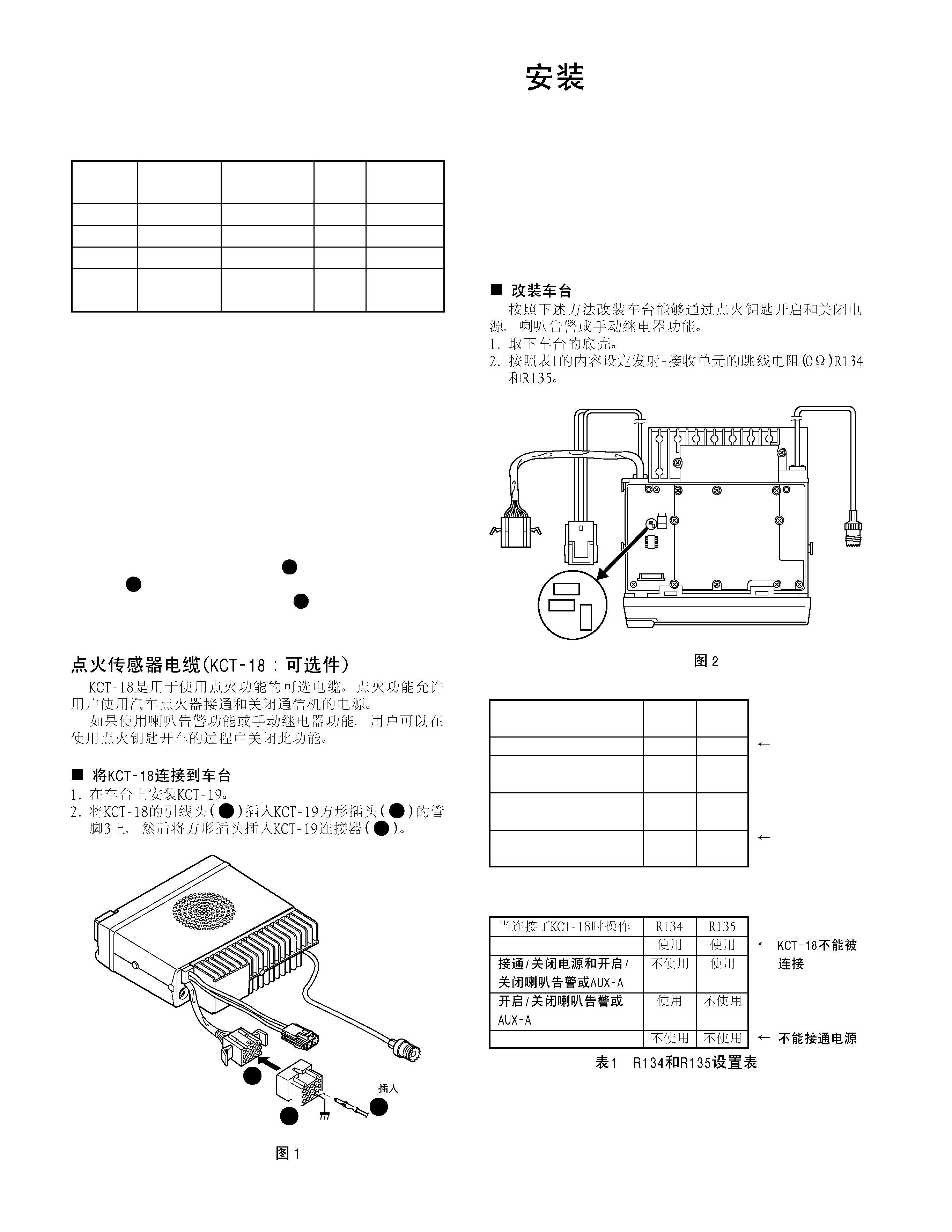
Ignition Sense Cable (KCT-18 : Option)
The KCT-18 is an optional cable for enabling the ignition
function. The ignition function lets you turn the power to the
transceiver on and off with the car ignition key.
If you use the Horn Alert function or the Manual Relay
function, you can turn the function off while driving with the
ignition key.
Connecting the KCT-18 to the Transceiver
1. Install the KCT-19 in the transceiver.
2. Insert the KCT-18 lead terminal (
) into pin 3 of the square
plug (
) supplied with the KCT-19, then insert the square
plug into the KCT-19 connector (
).
2
3
1
1
3
6
13
15
KCT-18
KCT-19
Contact /
!
2
3
1
Service Manual List
Title
Parts number
Remarks
Destination
TX-RX unit
PCB number
TK-868G
B51-8500-00
C,C3
J72-0678-02
TK-868G
B51-8502-00
M,M3
J72-0678-02
TK-868HG B51-8541-00 SUPPLEMENT
C
J72-0760-02
TK-868HG B51-8541-10 REVISED
C,C3
J72-0760-12
This Service manual
Frequency range
C,M
: 450~490MHz
C3,M3 : 400~430MHz
Fig. 1 /
Modifying the Transceiver
Modify the transceiver as follows to turn the power or the
Horn Alert or Manual Relay function on and off with the igni-
tion key.
1. Remove the lower half of the transceiver case.
2. Set jumper resistors (0
) R134 and R135 of the TX-RX unit
(A/2) as shown in Table 1.
TX-RX UNIT
(A/2)
ANT
KCT-19
CN2
R134
R133
R135
Fig. 2 /
Operation when KCT-18
R134
R135
is connected
Yes
Yes
KCT-18 cannot
Power on/off and Horn
No
Yes
be connected
Alert or AUX-A on/off
Horn Alert or AUX-A
Yes
No
on/off
No
No
Power cannot
be turned on
Table 1 R134 and R135 setup chart
3
TK-868HG
INSTALLATION /
1
3
2
!
"
3
W1
W2
CN1
CN2
KCT-19
Cushion /
(G13-1710-04)
CN3
CN7
CN3
Fig. 3 /
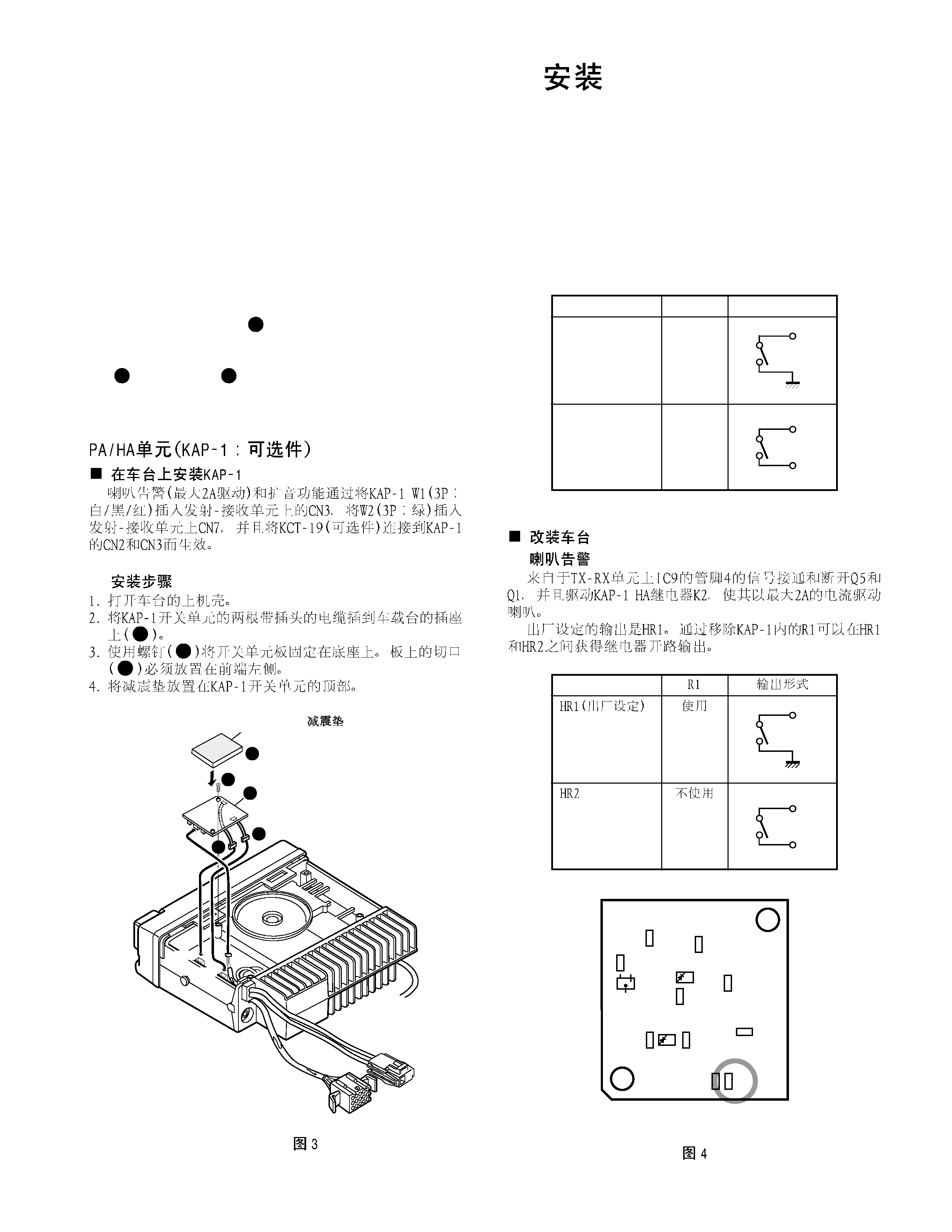
PA/HA Unit (KAP-1 : Option)
Installing the KAP-1 in the Transceiver
The Horn Alert (max. 2A drive) and Public Address func-
tions are enabled by inserting the KAP-1 W1 (3P; white/black/
red) into CN3 on the TX-RX unit, inserting W2 (3P; green) into
CN7 on the TX-RX unit, and connecting the KCT-19 (option) to
CN2 and CN3 of the KAP-1.
Installation procedure
1. Open the upper case of the transceiver.
2. Insert the two cables (
) with connectors from the KAP-
1 switch unit into the connectors on the transceiver.
3. Secure the switch unit board to the chassis with a screw
(
). The notch (
) in the board must be placed at the
front left side.
4. Attach the cushion on the top of the KAP-1 switch unit.
1
3
2
Modifying the Transceiver
Horn alert
The signal from pin 4 of IC9 on the TX-RX unit turns Q5
and Q1 on and off and drives KAP-1 HA relay K2 to drive the
horn with a maximum of 2A.
The default output is HR1. The relay open output can be
obtained between HR1 and HR2 by removing R1 in the KAP-
1.
R1
Output form
HR1 (Default)
Yes
HR2
No
04
04
04
4
Fig. 4 KAP-1 foil side view
04
04
04
4
TK-868HG
INSTALLATION /
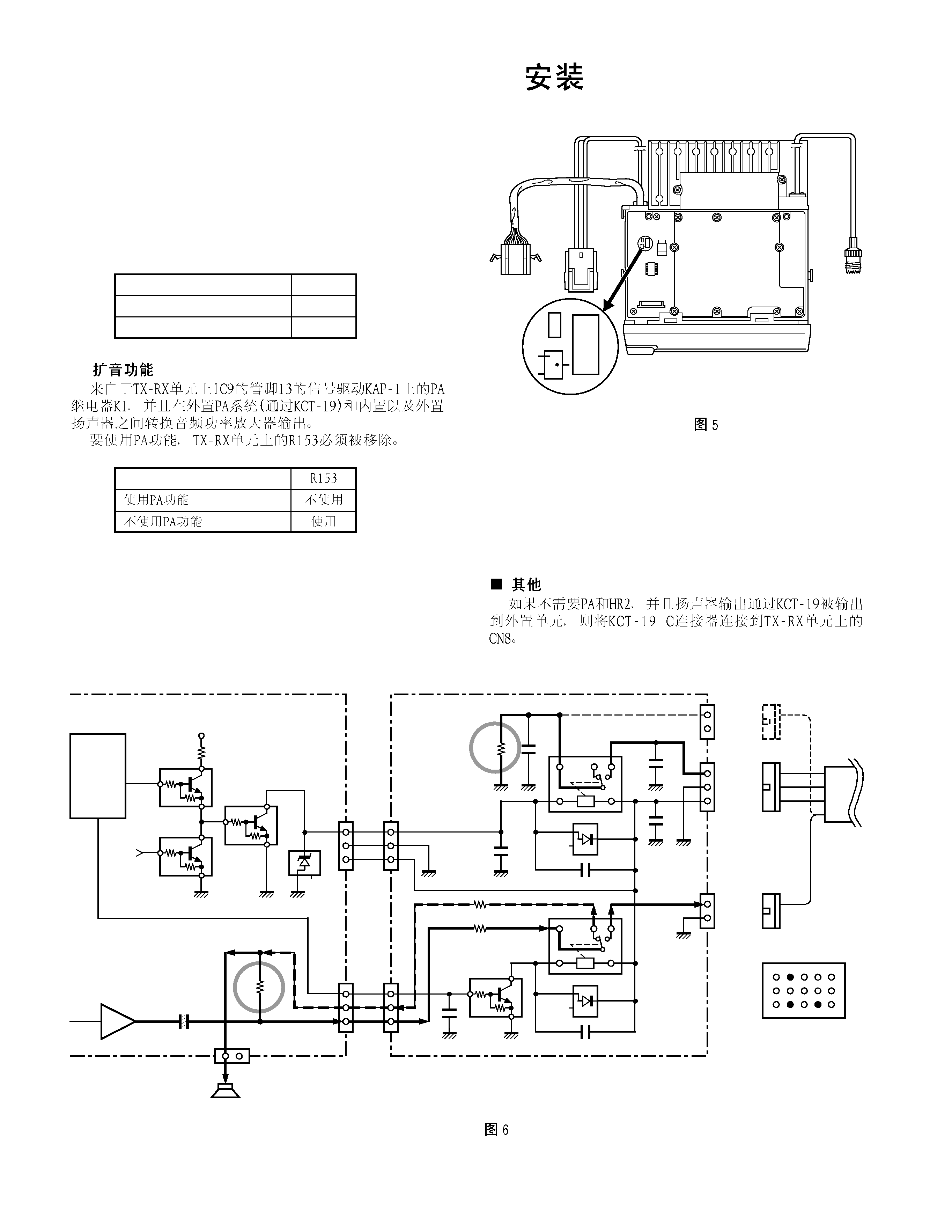
Public address
The signal from pin 13 of IC9 on the TX-RX unit drives PA
relay in the KAP-1 and switches the audio power amplifier
output between the external PA system (through KCT-19) and
internal and external speakers.
To use the PA function, R153 on the TX-RX unit must be
removed.
R153
Use the PA function
No
Do not use the PA function
Yes
TX-RX UNIT
(A/2)
KCT-19
CN2
Q19
R122
R153
ANT
Fig. 5 /
Others
If the PA and HR2 are not necessary and the speaker out-
put is output to an external unit through the KCT-19, connect
the KCT-19 C connector to CN8 on the TX-RX unit.
8C
R21
Q5
Q1
D2
Q6
Q1
Q6
4
IC9
Shift
register
IGN
±
+
±
+
KAP-1 (SWITCH UNIT : X41-3380-20)
W1
1
2
3
HOR
E
SB
W2
1
2
3
PA/LI
SPO
SPI
CN1
1
2
HR2
NC
CN2
1
2
3
HR1
E
SB
CN3
1
2
PAO/LIO
E
R1
0
C5
1000P
C6
1000P
C7
1000P
K2
D1
C3 0.01
C1
1000P
R3 0
R4 0
C2
1000P
D2
K1
C4 0.01
Q1
Q1 : DTD114EK
D1,2 : 1SS193
CN3
CN7
13
+
R153
Audio
power amp
IC13
CN8
1
2
SP
E
Internal/External
speaker
TX-RX UNIT
B
BRN
ORG
YEL
C
C
GRN
GRN
KCT-19
13 10
1
3
6
12
15
KCT-19 Terminal
6 : Earth
10 : HR1
12 : PA (HR2)
Fig. 6 /
5
TK-868HG
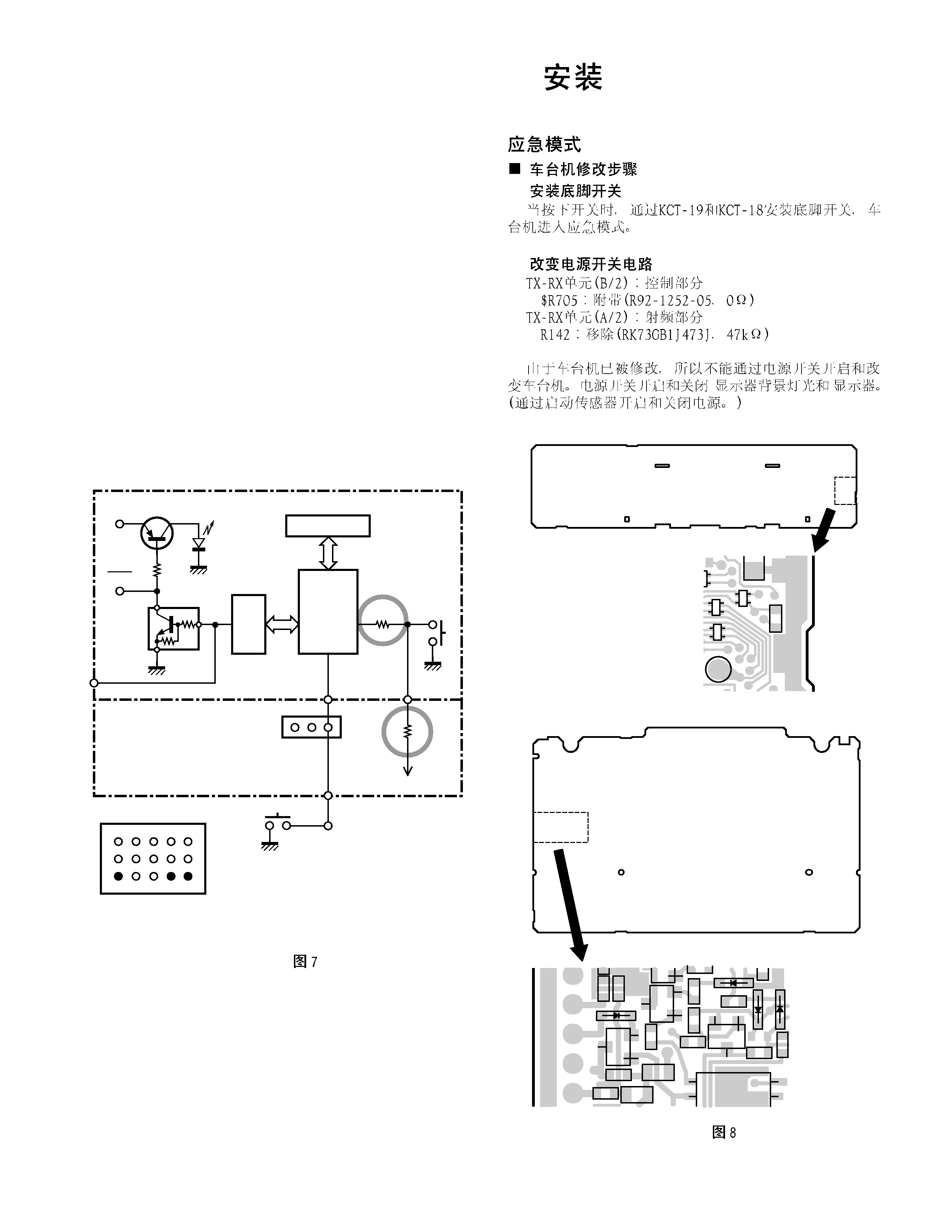
Emergency Mode
Transceiver Modification Procedure
install the foot switch
Install the foot switch through the KCT-19 and KCT-18.
When the switch is treaded on, the radio enters the emer-
gency mode.
Change the power switch circuit
TX-RX unit (B/2) : Control section
$R705 : Attach (R92-1252-05, 0
)
TX-RX unit (A/2) : RF section
R142 : Remove (RK73GB1J473J, 47k
)
Once the transceiver is modified, it cannot be turned on
and off with the power switch. The power switch turns the
LCD backlight and display on and off. (The power is switched
on and off by IGNITION SENSE.)
IC502
CPU
6
Q506
87
88
25
20
$R705
Attach
0
Power
switch
MBL
MBL
SB
Q505
Key
backlight
LCD
IC510
1
3
CN5
R142
47K
Remove
IC14
KCT-19
15 pin
KCT-18
Foot
switch
Control section
TX-RX section
Outside
13
1
3
6
15
KCT-19 Terminal
3 : Ignition sense
6 : Earth
15 : Foot switch
F.RESET
R705
TX-RX unit B/2
Foil side
R142
TX-RX unit A/2
Foil side
Fig. 7 /
Fig. 8 /
INSTALLATION /