© 2003-6 PRINTED IN JAPAN
B51-8639-10 (N) PDF
UHF FM TRANSCEIVER
TK-8108H
SERVICE MANUAL
Panel assy
(A62-0942-03)
Front glass
(B10-2753-03)
Cabinet
(A01-2181-01)
Chassis
(A10-4048-21)
Key top
(K29-9065-01)
Modular jack
(E08-0877-05)
GENERAL .................................................. 2
SYSTEM SET-UP ...................................... 3
OPERATING FEATURES .......................... 4
REALIGNMENT ......................................... 8
INSTALLATION ....................................... 11
DISASSEMBLY FOR REPAIR ................. 13
CIRCUIT DESCRIPTION .......................... 14
SEMICONDUCTOR DATA ...................... 18
COMPONENTS DESCRIPTION .............. 20
PARTS LIST ............................................. 21
EXPLODED VIEW .................................... 27
PACKING ................................................. 28
ADJUSTMENT ........................................ 29
TERMINAL FUNCTION ........................... 34
PC BOARD
DISPLAY UNIT (X54-3460-20) ............ 35
TX-RX UNIT (X57-6710-24) ................ 37
SCHEMATIC DIAGRAM .......................... 43
BLOCK DIAGRAM ................................... 47
LEVEL DIAGRAM .................................... 49
SPECIFICATION ...................................... 51
CONTENTS
REVISED
This service manual applies to products with 50300001 or subsequent serial numbers.
In terms of the products with the serial numbers earlier than 50300001, refer to the TK-8108H service manual as per part No.
B51-8639-00.
Service Manual List
Title
Parts number
Remarks
Destination
TX-RX unit number
Display unit number
TK-8108H
B51-8639-00
M
X57-6390-20
X54-3340-20
TK-8108H
B51-8639-10
REVISED
M
X57-6710-24
X54-3460-20
(This service manual)

TK-8108H
2
INTRODUCTION
SCOPE OF THIS MANUAL
This manual is intended for use by experienced techni-
cians familiar with similar types of commercial grade commu-
nications equipment. It contains all required service informa-
tion for the equipment and is current as of this publication
date. Changes which may occur after publication are covered
by either Service Bulletins or Manual Revisions, which are
issued as required.
ORDERING REPLACEMENT PARTS
When ordering replacement parts or equipment informa-
tion, the full part identification number should be included.
This applies to all parts : components, kits, and chassis. If the
part number is not known, include the chassis or kit number
of which it is a part and a sufficient description of the required
component for proper identification.
PERSONNEL SAFETY
The following precautions are recommended for person-
nel safety :
·DO NOT transmit if someone is within two feet (0.6
meter) of the antenna.
·DO NOT transmit until all RF connectors are secure and
any open connectors are properly terminated.
· SHUT OFF this equipment when near electrical blasting
caps or while in an explosive atmosphere.
· All equipment should be properly grounded before power-
up for safe operation.
· This equipment should be serviced by only qualified tech-
nicians.
PRE-INSTALLATION CONSIDERATIONS
1. UNPACKING
Unpack the radio from its shipping container and check for
accessory items. If any item is missing, please contact
KENWOOD immediately.
2. LICENSING REQUIREMENTS
Federal regulations require a station license for each radio
installation (mobile or base) be obtained by the equipment
owner. The licensee is responsible for ensuring transmitter
power, frequency, and deviation are within the limits permit-
ted by the station license.
Transmitter adjustments may be performed only by a li-
censed technician holding an FCC first, second or general
class commercial radiotelephone operator's license. There is
no license required to install or operate the radio.
3. PRE-INSTALLATION CHECKOUT
3-1. Introduction
Each radio is adjusted and tested before shipment. How-
ever, it is recommended that receiver and transmitter opera-
tion be checked for proper operation before installation.
3-2. Testing
The radio should be tested complete with all cabling and
accessories as they will be connected in the final installation.
Transmitter frequency, deviation, and power output should
be checked, as should receiver sensitivity, squelch operation,
and audio output. Signalling equipment operation should be
verified.
4. PLANNING THE INSTALLATION
4-1. General
Inspect the vehicle and determine how and where the ra-
dio antenna and accessories will be mounted.
Plan cable runs for protection against pinching or crushing
wiring, and radio installation to prevent overheating.
4-2. Antenna
The favored location for an antenna is in the center of a
large, flat conductive area, usually at the roof center. The
trunk lid is preferred, bond the trunk lid and vehicle chassis
using ground straps to ensure the lid is at chassis ground.
4-3. Radio
The universal mount bracket allows the radio to be
mounted in a variety of ways. Be sure the mounting surface
is adequate to support the radio's weight. Allow sufficient
space around the radio for air cooling. Position the radio close
enough to the vehicle operator to permit easy access to the
controls when driving.
4-4. DC Power and wiring
1. This radio may be installed in negative ground electrical
systems only. Reverse polarity will cause the cable fuse to
blow. Check the vehicle ground polarity before installation
to prevent wasted time and effort.
2. Connect the positive power lead directly to the vehicle
battery positive terminal. Connecting the Positive lead to
any other positive voltage source in the vehicle is not rec-
ommended.
3. Connect the ground lead directly to the battery negative
terminal.
4. The cable provided with the radio is sufficient to handle
the maximum radio current demand. If the cable must be
extended, be sure the additional wire is sufficient for the
current to be carried and length of the added lead.
GENERAL
TK-8108H
3
5. INSTALLATION PLANNING CONTROL STATIONS
5-1. Antenna system
Control station. The antenna system selection depends on
many factors and is beyond the scope of this manual. Your
KENWOOD dealer can help you select an antenna system
that will best serve your particular needs.
5-2. Radio location
Select a convenient location for your control station radio
which is as close as practical to the antenna cable entry point.
Secondly, use your system's power supply (which supplies
the voltage and current required for your system). Make sure
sufficient air can flow around the radio and power supply to
allow adequate cooling.
SERVICE
This radio is designed for easy servicing. Refer to the
schematic diagrams, printed circuit board views, and align-
ment procedures contained in this manual.
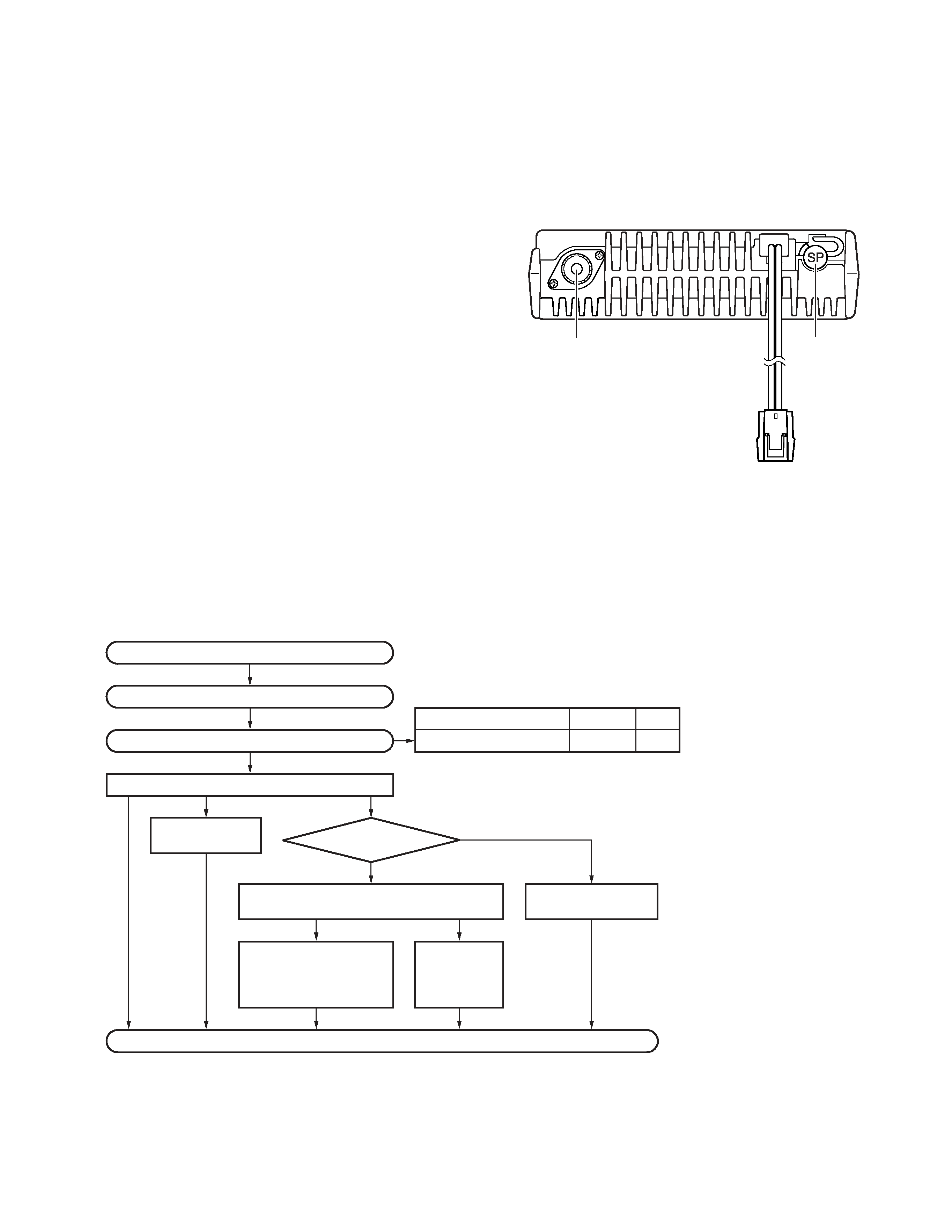
Speaker
jack cap
Power input
connector
Antenna
connector
NOTE
If you do not intend to use the 3.5-mm jack for the external
speaker, fit the supplied speaker-jack cap to stop dust and
sand from getting in.
Merchandise received
License and frequency allocated by FCC
Choose the type of transceiver
Transceiver programming
KCT-39
Connection cable
KCT-18
Ignition sense cable
KCT-36
Extension cable
KDS-100
Mobile data
terminal
KGP-2A
Modem GPS receiver or
KGP-2B
Modem GPS controller
KES-3
External speaker
See page 8.
A personal computer (IBM PC or compatible), programming interface (KPG-46),
and programming software (KPG-70D) are required for programming.
Frequency range (MHz)
RF power
Type
450~490
45W
M
(Option)
(Option)
(Option)
(Option)
(Option)
(Option)
or
Delivery
GENERAL / SYSTEM SET-UP
SYSTEM SET-UP
TK-8108H
4
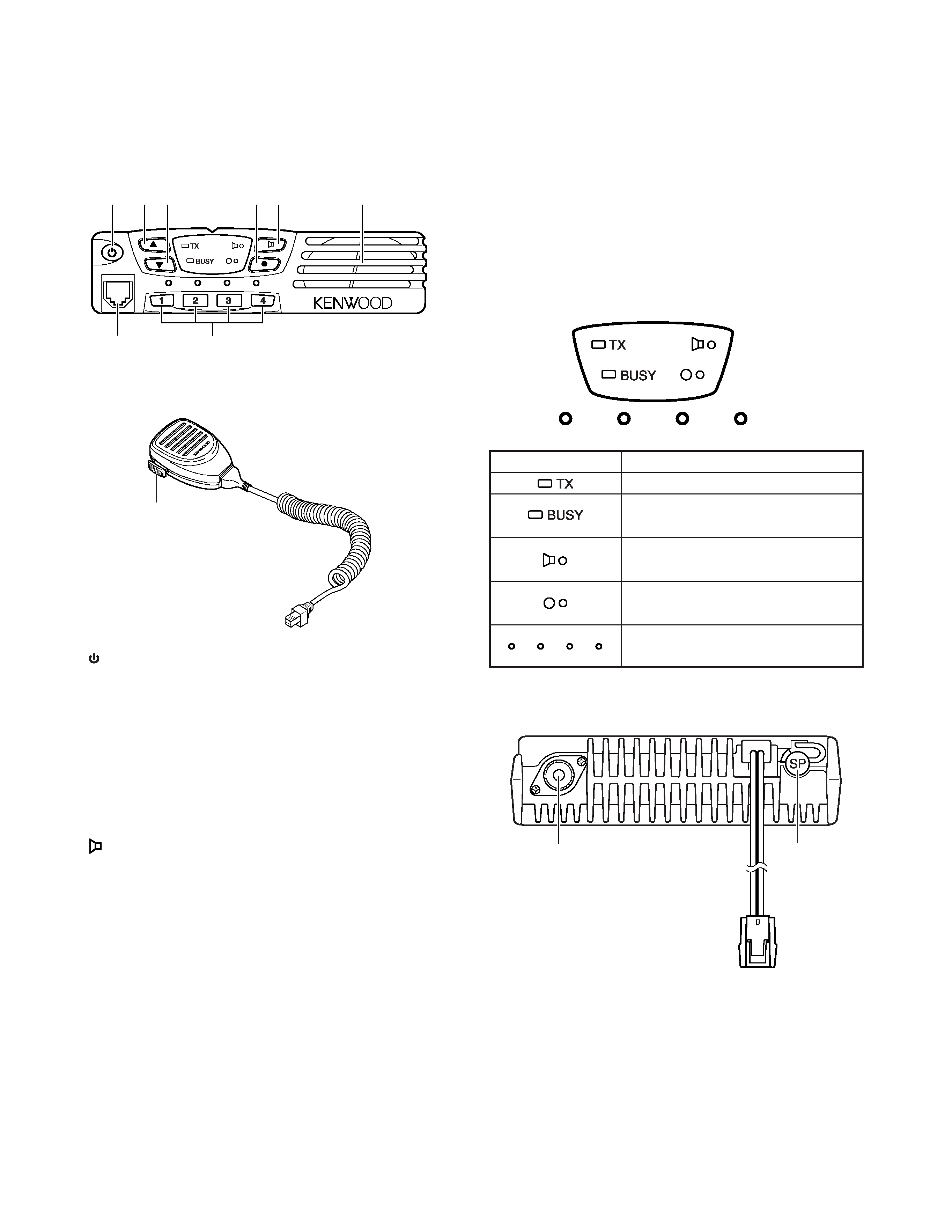
OPERATING FEATURES
Indicator
Description
Light while transmitting.
Lights when a signal is detected on
the currently selected channel.
Lights while the function programmed
onto its corresponding key is activated.
Lights while the function programmed
onto its corresponding key is activated.
Lights to display the currently selected
channel (1~4) or (5~8).
1-5. Rear panel
External
speaker
jack
Power input
connector
Antenna
connector
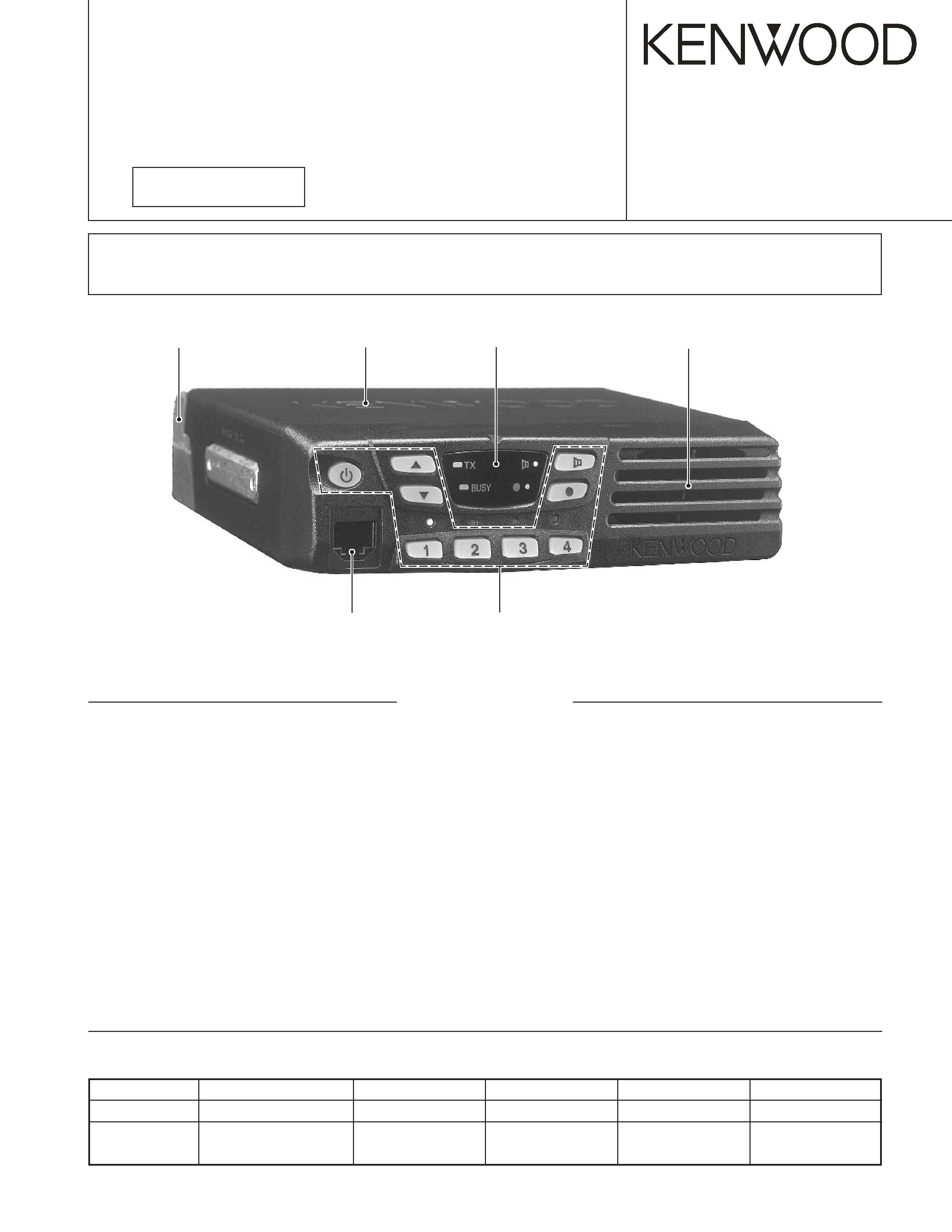
1. Controls and Functions
1-1. Front Panel
q
(Power) switch
Press to switch the transceiver ON. Press and hold for
approximately 1 seconds to switch the transceiver OFF.
w
key
Press to increase the volume level.
e
key
Press to decrease the volume level.
r
key
PF (Programmable Function) key. The default setting of
this key is None (no function). The programmable func-
tions available for this key are listed below.
t
key
PF (Programmable Function) key. The default setting of
this key is Monitor. Other programmable functions avail-
able for this key are listed below.
y 1/ 2/ 3/ 4 keys
Press to select a channel from 1 to 4.
u Microphone jack
Insert the microphone plug into this jack (the microphone
is an optional accessory).
i Speaker
Internal speaker.
o PTT switch
Press this switch, then speak into the microphone to call a
station.
1-2. Microphone
q
we
t
r
y
u
i
o
1-3. Auxiliary Programmable Functions
· Emergency
· Scan On/OFF
· Key Lock
· Talk Around
· Monitor
· Temporary Delete
· None (no function)
· AUX
· Horn Alert
· Scan + Temporary Delete
· Group
1-4. Display

TK-8108H
5
2. Operation Features
The TK-8108H is a UHF FM radio designed to operate in
conventional format. The programmable features are sum-
marized.
3. Transceiver Controls and Indicators
3-1. Front Panel Controls
All the keys on the front panel are momentary-type push
buttons. The functions of these keys are explained below.
· POWER key
Transceiver POWER key. When the power is switched
off, all the parameters are stored in memory. When the
power is switched on again, the transceiver returns to the
previous conditions.
· CHANNEL keys
· MONITOR key (Programmable)
·
key (Programmable)
· VOLUME UP/DOWN key
When the key is pressed, the volume level is increased/
decreased and repeats if held for 200ms or longer.
· BUSY/TX LED
The BUSY indicator (Green LED) shows that the channel is
in use. The TX indicator (Red LED) shows that you are trans-
mitting.
3-2. Programmable Keys
The FPU (KPG-70D) enables programmable keys to select
the following functions.
· Emergency
· Key Lock
· Monitor
· Scan ON/OFF
· Talk Around
· Temporary Delete
· None
· AUX
· Horn Alert
· Scan + Temporary Delete
· Group
· Emergency
Pressing this key for longer than 1 second causes the
transceiver to enter the emergency mode. The transceiver
jumps to the programmed "Emergency channel" and trans-
mits for 25* seconds.
The transceiver disables mic mute while transmitting. Af-
ter finishing transmission, the transceiver receivers for 5*
seconds. The transceiver Mute* the speaker while receiving.
Following the above sequence, the transceiver continues to
transmit and receive.
* Default value.
· Key lock
Pressing this key causes the transceiver to accept entry of
only the [Vol Up/Down]*, [Key lock], Microphone [PTT],
[Monitor], [Emergency], and [Power] keys.
* Programmable
· Monitor
Used to release signalling (press once) or squelch (press
and hold for approximately two seconds) when operating as a
conventional. It is also used to reset option signalling.
· Scan ON/OFF
Press this key starts scanning. Pressing this key stops
scanning.
· Talk around
Press this key, the transceiver uses the receive frequency
and the tone for transmission.
The operator can call the other party directly (without re-
peater). Press this key again, the talk around function goes
off.
· Temporary delete
The "Add" channel contained in the scan sequence, and
"Delete" channel is not contained. In the scan mode, this
key switches the channel delete temporarily (Press and hold
for approximately one second).
When the transceiver is turned off, the transceiver exits
the scan or switches the scan function off.
· None
Sounds error operation beep, and no action will occur.
Use this function when the transceiver is required to be more
simple operated.
· AUX
Press to activate the auxiliary port. Press again to deacti-
vate the auxiliary port. Auxiliary is used with optional boards,
allowing you to activate and deactivate these optional func-
tions. While activated, the AUX icon appears on the display.
· Horn alert
Horn Alert is a useful feature that will notify you of a re-
ceived call while you are away from your vehicle. The trans-
ceiver is programmed to sound the vehicle horn or some
other external alert device (such as the vehicle headlights)
when a call is received that has correct signalling.
· Scan + Temporarily delete
To temporarily remove a channel from the Scan list, press
and hold this key for approximately one second during Scan,
while Scan is paused on the undesired channel, to tempo-
rarily remove that channel from the scanning sequence. Af-
ter switching the Scan function OFF, or switching the trans-
ceiver OFF and then ON again, the Scan settings return to
normal.
OPERATING FEATURES