© 2003-11 PRINTED IN JAPAN
B51-8670-00 (N) 119
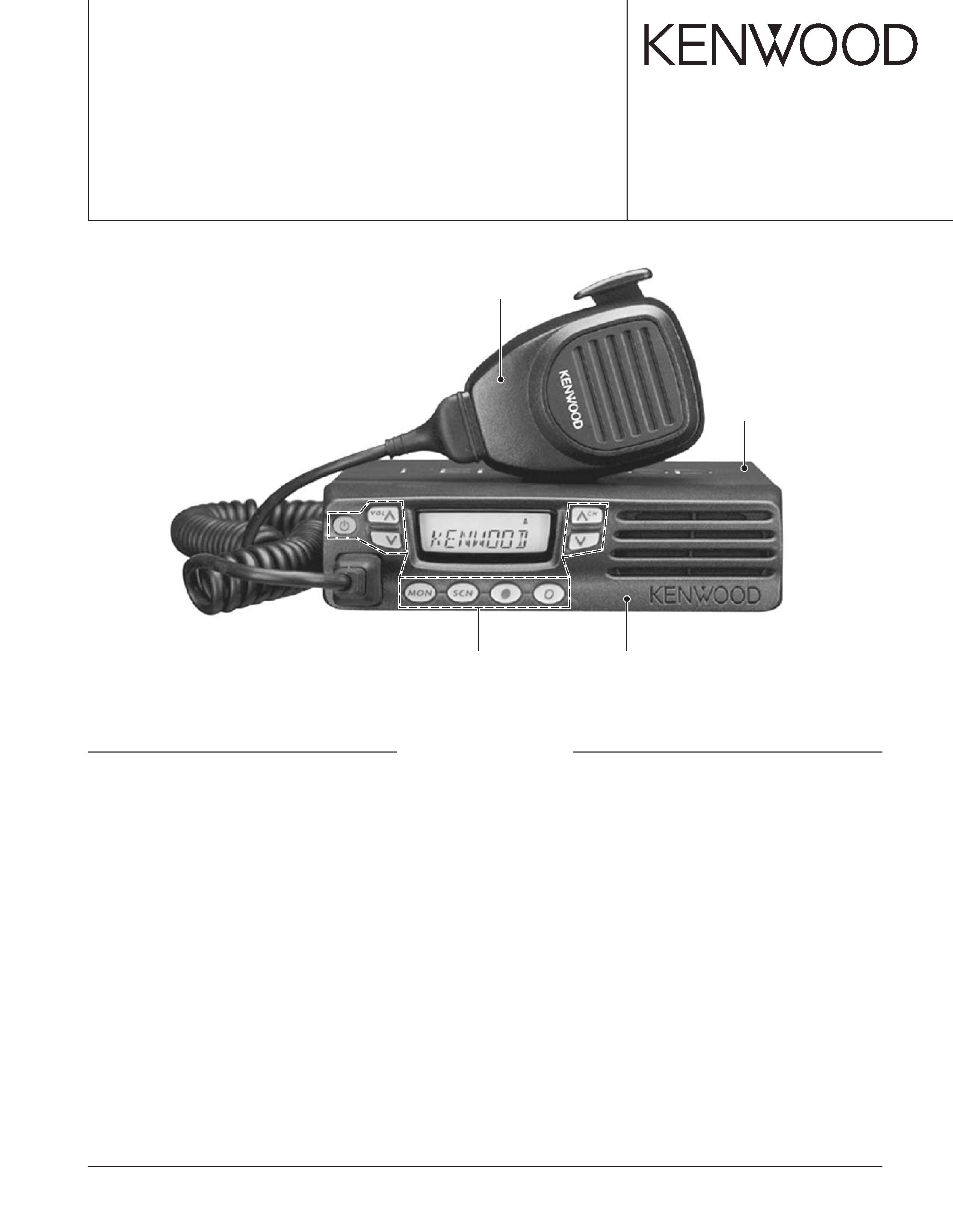
VHF FM TRANSCEIVER
TK-7100
SERVICE MANUAL
Microphone
(T91-0624-05) : K
Cabinet
(A01-2178-02)
Panel assy
(A62-1074-03)
Key top
(K29-9262-01)
GENERAL .................................................. 2
SYSTEM SET-UP ...................................... 3
OPERATING FEATURES .......................... 4
REALIGNMENT ......................................... 5
INSTALLATION ....................................... 11
DISASSEMBLY FOR REPAIR ................. 14
CIRCUIT DESCRIPTION .......................... 17
SEMICONDUCTOR DATA ...................... 22
COMPONENTS DESCRIPTION .............. 23
PARTS LIST ............................................. 24
EXPLODED VIEW .................................... 30
PACKING ................................................. 31
ADJUSTMENT ........................................ 32
PC BOARD
DISPLAY UNIT (X54-3430-20) ............ 36
TX-RX UNIT (X57-6910-XX) ............... 38
SCHEMATIC DIAGRAM .......................... 42
BLOCK DIAGRAM ................................... 46
LEVEL DIAGRAM .................................... 48
TERMINAL FUNCTION ........................... 50
SPECIFICATION ...................................... 51
CONTENTS

TK-7100
2
INTRODUCTION
SCOPE OF THIS MANUAL
This manual is intended for use by experienced techni-
cians familiar with similar types of commercial grade commu-
nications equipment. It contains all required service informa-
tion for the equipment and is current as of this publication
date. Changes which may occur after publication are covered
by either Service Bulletins or Manual Revisions, which are
issued as required.
ORDERING REPLACEMENT PARTS
When ordering replacement parts or equipment informa-
tion, the full part identification number should be included.
This applies to all parts : components, kits, and chassis. If the
part number is not known, include the chassis or kit number
of which it is a part and a sufficient description of the required
component for proper identification.
PERSONAL SAFETY
The following precautions are recommended for personal
safety :
·DO NOT transmit if someone is within two feet (0.6
meter) of the antenna.
·DO NOT transmit until all RF connectors are secure and
any open connectors are properly terminated.
· SHUT OFF this equipment when near electrical blasting
caps or while in an explosive atmosphere.
· All equipment should be properly grounded before power-
up for safe operation.
· This equipment should be serviced by only qualified tech-
nicians.
PRE-INSTALLATION CONSIDERATIONS
1. UNPACKING
Unpack the radio from its shipping container and check for
accessory items. If any item is missing, please contact
KENWOOD immediately.
2. LICENSING REQUIREMENTS
Federal regulations require a station license for each radio
installation (mobile or base) be obtained by the equipment
owner. The licensee is responsible for ensuring transmitter
power, frequency, and deviation are within the limits permit-
ted by the station license.
Transmitter adjustments may be performed only by a li-
censed technician holding an FCC first, second or general
class commercial radiotelephone operator's license. There is
no license required to install or operate the radio.
3. PRE-INSTALLATION CHECKOUT
3-1. Introduction
Each radio is adjusted and tested before shipment. How-
ever, it is recommended that receiver and transmitter opera-
tion be checked for proper operation before installation.
3-2. Testing
The radio should be tested complete with all cabling and
accessories as they will be connected in the final installation.
Transmitter frequency, deviation, and power output should
be checked, as should receiver sensitivity, squelch operation,
and audio output. Signalling equipment operation should be
verified.
4. PLANNING THE INSTALLATION
4-1. General
Inspect the vehicle and determine how and where the ra-
dio antenna and accessories will be mounted.
Plan cable runs for protection against pinching or crushing
wiring, and radio installation to prevent overheating.
4-2. Antenna
The favored location for an antenna is in the center of a
large, flat conductive area, usually at the roof center. The
trunk lid is preferred, bond the trunk lid and vehicle chassis
using ground straps to ensure the lid is at chassis ground.
4-3. Radio
The universal mount bracket allows the radio to be
mounted in a variety of ways. Be sure the mounting surface
is adequate to support the radio's weight. Allow sufficient
space around the radio for air cooling. Position the radio close
enough to the vehicle operator to permit easy access to the
controls when driving.
4-4. DC Power and wiring
1. This radio may be installed in negative ground electrical
systems only. Reverse polarity will cause the cable fuse to
blow. Check the vehicle ground polarity before installation
to prevent wasted time and effort.
2. Connect the positive power lead directly to the vehicle
battery positive terminal. Connecting the Positive lead to
any other positive voltage source in the vehicle is not rec-
ommended.
3. Connect the ground lead directly to the battery negative
terminal.
4. The cable provided with the radio is sufficient to handle
the maximum radio current demand. If the cable must be
extended, be sure the additional wire is sufficient for the
current to be carried and length of the added lead.
GENERAL
TK-7100
3
5. INSTALLATION PLANNING CONTROL STATIONS
5-1. Antenna system
Control station. The antenna system selection depends on
many factors and is beyond the scope of this manual. Your
KENWOOD dealer can help you select an antenna system
that will best serve your particular needs.
5-2. Radio location
Select a convenient location for your control station radio
which is as close as practical to the antenna cable entry point.
Secondly, use your system's power supply (which supplies
the voltage and current required for your system). Make sure
sufficient air can flow around the radio and power supply to
allow adequate cooling.
SERVICE
This radio is designed for easy servicing. Refer to the
schematic diagrams, printed circuit board views, and align-
ment procedures contained in this manual.
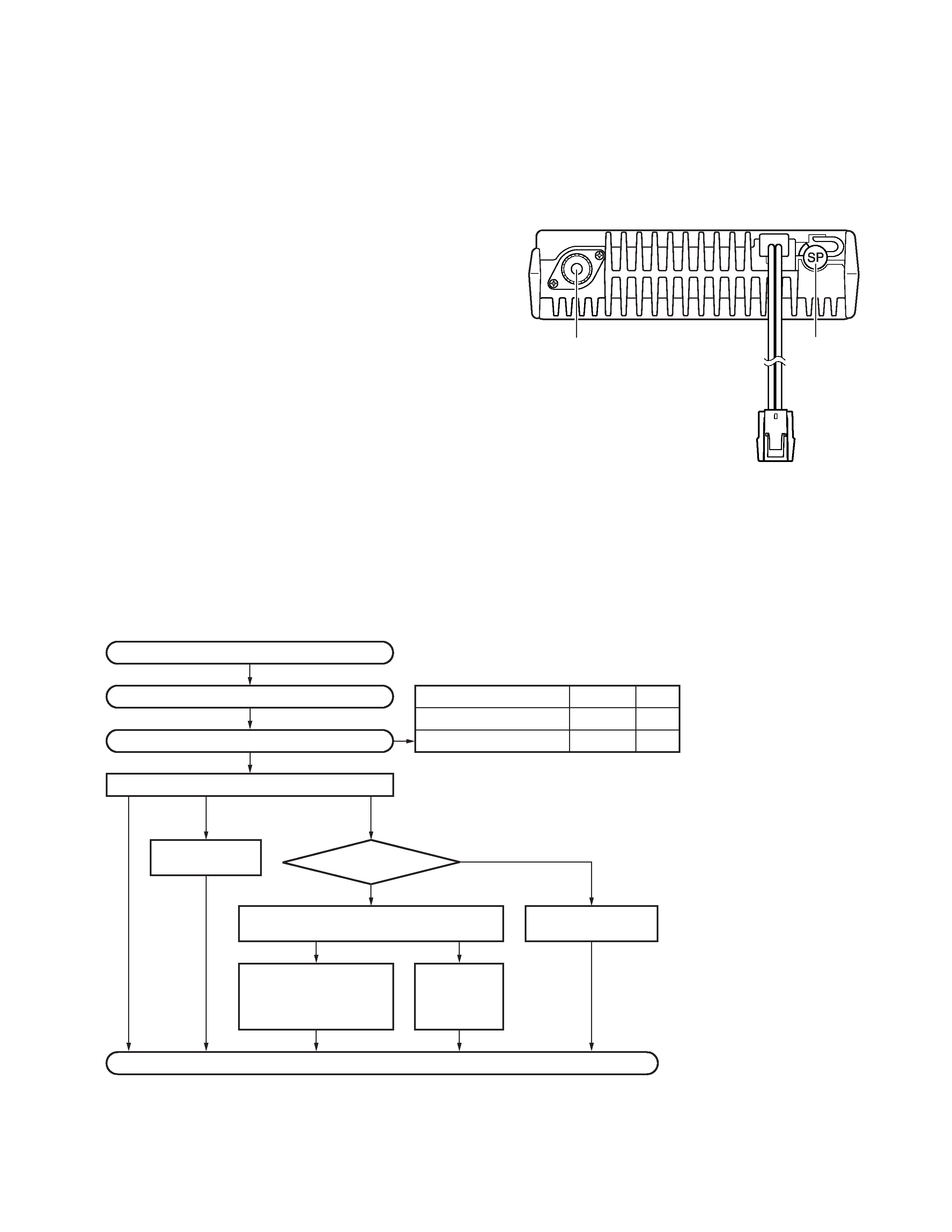
Speaker
jack cap
Power input
connector
Antenna
connector
NOTE
If you do not intend to use the 3.5-mm jack for the external
speaker, fit the supplied speaker-jack cap to stop dust and
sand from getting in.
Merchandise received
License and frequency allocated by FCC
Choose the type of transceiver
Transceiver programming
KCT-39
Connection cable
KCT-18
Ignition sense cable
KCT-36
Extension cable
KDS-100
Mobile data
terminal
KGP-2A
Modem GPS receiver or
KGP-2B
Modem GPS controller
KES-3
External speaker
See page 5.
A personal computer (IBM PC or compatible), programming interface (KPG-46),
and programming software (KPG-80D)* are required for programming.
* The market of M2 uses 2.0 or more versions.
Frequency range (MHz)
RF power
Type
136~162
25W
M2
146~174
25W
K,M
(Option)
(Option)
(Option)
(Option)
(Option)
(Option)
or
Delivery
GENERAL / SYSTEM SET-UP
SYSTEM SET-UP
TK-7100
4
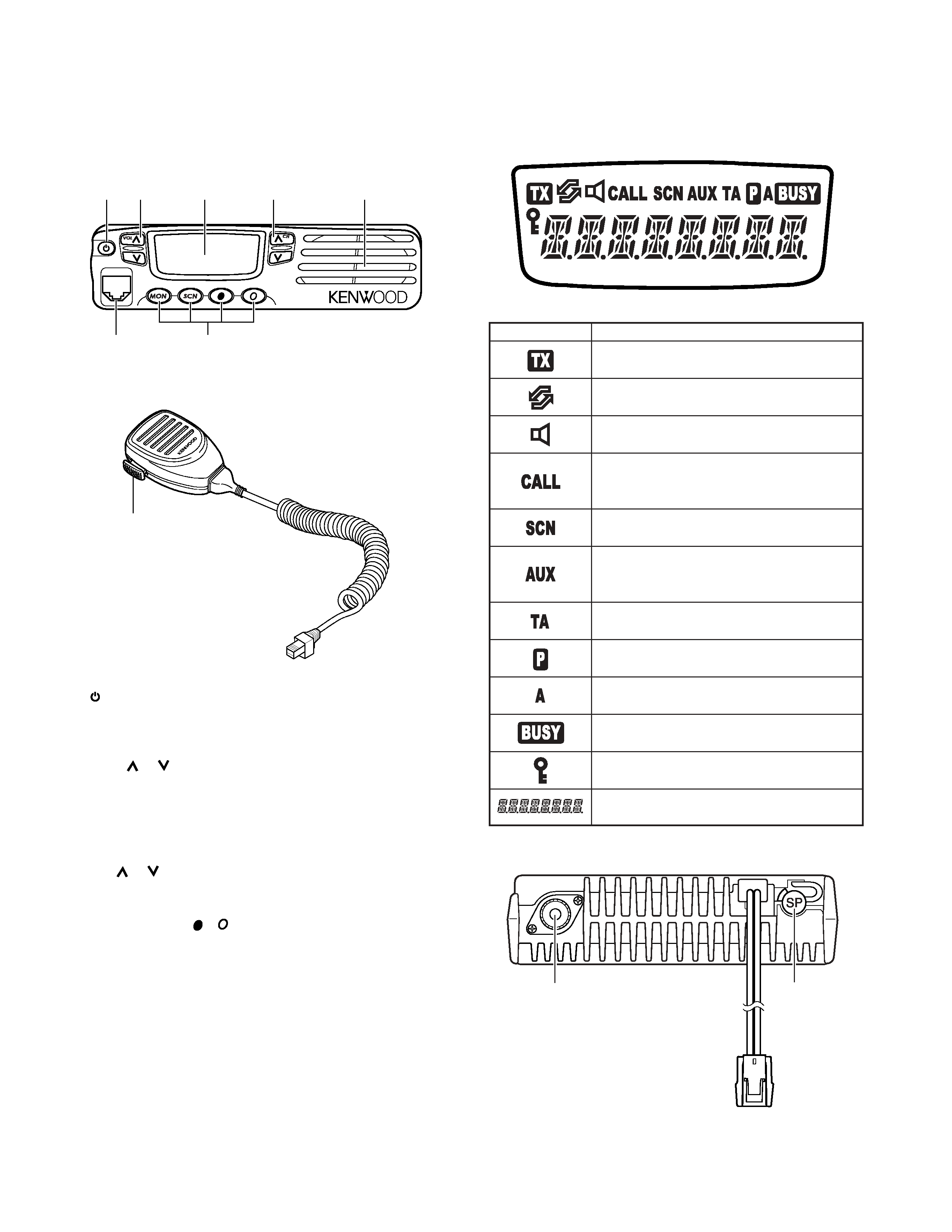
OPERATING FEATURES
1. Controls and Functions
1-1. Front Panel
1-2. Microphone
q
we
r
u
t
y
i
q
(Power) switch
Press to switch the transceiver ON. Press and hold for
approximately 1 second to switch the transceiver OFF.
w VOL
/
keys (left side)
Press to increase or decrease the volume level.
e Display
Refer to right.
r CH
/
keys (right side)
Press to increase or decrease the channel number.
t MON / SCN /
/
keys
PF (Programmable Function) keys. Press each key to acti-
vate its programmable function.
y Microphone jack
Insert the microphone plug into this jack.
u Speaker
Internal speaker.
i PTT switch
Press this switch, then speak into the microphone to call a
station.
1-3. Display
Indicator
Description
Appears while transmitting.
Appears when trunking is activated.
Appears while monitoring the selected channel
(squelch is off).
Appears when making a call using Code
Squelch or Selective Call. Appears and blinks
when receiving a Code Squelch call.
Appears while scanning.
Appears when the AUX port has been
activated or when the Scrambler function has
been selected.
Appears while using the Talk Around function.
The selected channel is set as a Priority
channel.
The selected channel is added to the scanning
sequence.
Appears when a signal is detected on the
currently selected channel.
Appears when the transceiver keys have been
locked, using the Key Lock function.
Displays the currently selected group and
channel number, or the channel name.
1-4. Rear Panel
External
speaker
jack
Power input
connector
Antenna
connector
TK-7100
5
REALIGNMENT
1. Modes
User mode
PC mode
PC programming mode
Clone mode
PC test mode
PC tuning mode
Self programming mode
Mode
Function
User mode
For normal use.
PC mode
Used for communication between the
radio and PC (IBM compatible).
PC programming
Used to read and write frequency data
mode
and other features to and from the radio.
PC test mode
Used to check the radio using the PC.
This feature is included in the FPU.
PC tuning mode
Used to tune the radio using the PC.
Clone mode
Used to transfer programming data from
one radio to another.
Self programming
You can program the frequency, signalling
mode
and other functions using only the radio.
2. How to Enter Each Mode
Mode
Operation
User mode
Power ON
PC mode
Received commands from PC
Clone mode
[CH DOWN]+Power ON (Two seconds)
Self programming mode
[MON]+Powr ON (Two seconds)
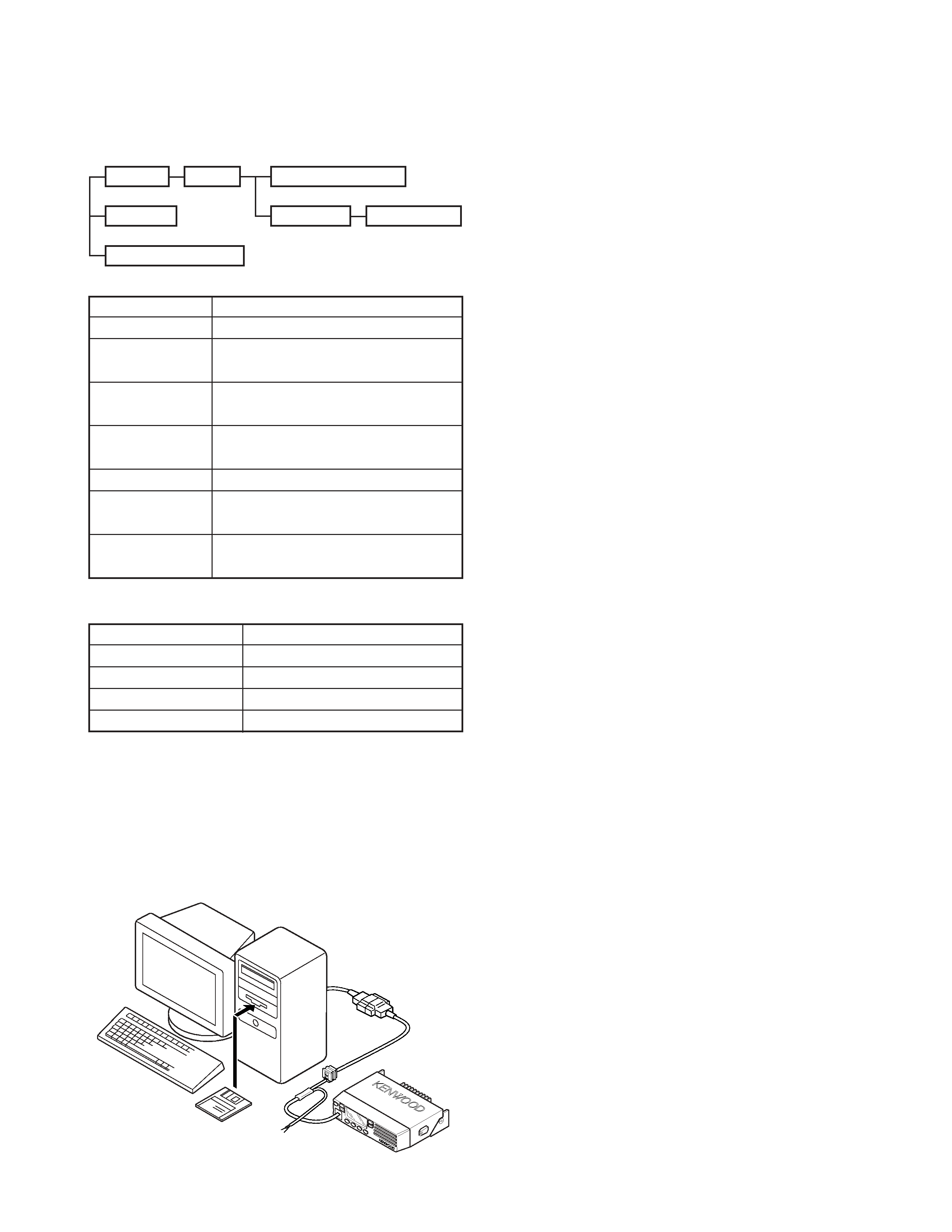
3. PC Mode
3-1. Preface
The TK-7100 transceiver is programmed using a personal
computer, a programming interface (KPG-46) and program-
ming software (KPG-80D).
The programming software can be used with an IBM PC
or compatible. Figure 1 shows the setup of an IBM PC for
programming.
3-2. Connection Procedure
1. Connect the TK-7100 to the personal computer with the
interface cable.
2. When the Power is switched on, user mode can be en-
tered immediately. When the PC sends a command, the
radio enters PC mode.
When data is transmitted from transceiver, the TX indica-
tor blink.
When data is received by the transceiver, the BUSY indi-
cator blink.
In the PC mode, " PC " is displayed on the LCD.
3-3. KPG-46 Description
(PC programming interface cable : Option)
The KPG-46 is required to interface the TK-7100 to the
computer. It has a circuit in its D-subconnector (25-pin) case
that converts the RS-232C logic level to the TTL level.
The KPG-46 connects the modular microphone jack of the
TK-7100 to the computers RS-232C serial port.
3-4. Programming Software Description
KPG-80D is the programming software for TK-7100 sup-
plied on three 3.5" floppy diskettes. This software runs un-
der Windows 98, ME, Windows 2000 or XP on an IBM-PC or
compatible machine.
The data can be input to or read from TK-7100 and edited
on the screen. The programmed or edited data can be
printed out. It is also possible to tune the transceiver.
4. Clone Mode
Programming data can be transferred from one radio to
another by connecting them via their modular microphone
jacks. The operation is as follows (the transmit radio is the
master and the receive radio is the slave).
Note :
Clone mode should be enabled.
1. Turn the master TK-7100 power ON with the [CH DOWN]
key held down (2 seconds), " CLONE " is displayed on
the LCD.
2. Power on the slave TK-7100.
3. Connect the cloning cable (No. E30-3382-05) to the modu-
lar microphone jacks on the master and slave.
4. Press the [MON] key on the master TK-7100 transceiver.
The data of the master is sent to the slave. While the
master is sending data, [TX] icon blinked. While the slave
is receiving the data, " PC " is displayed and [BUSY] icon
blinked. When cloning of data is completed, the master
displays "END", and the master [TX] icon turned off, and
the slave automatically operates in the User mode. The
slave can then be operated by the same program as the
master.
5. The other slave can be continuously cloned. Carry out the
operation in step 2 to 4.
Fig. 1
IBM-PC
KPG-46
TK-7100
KPG-80D