© 2001-3 PRINTED IN JAPAN
B51-8408-20 (N) 1015
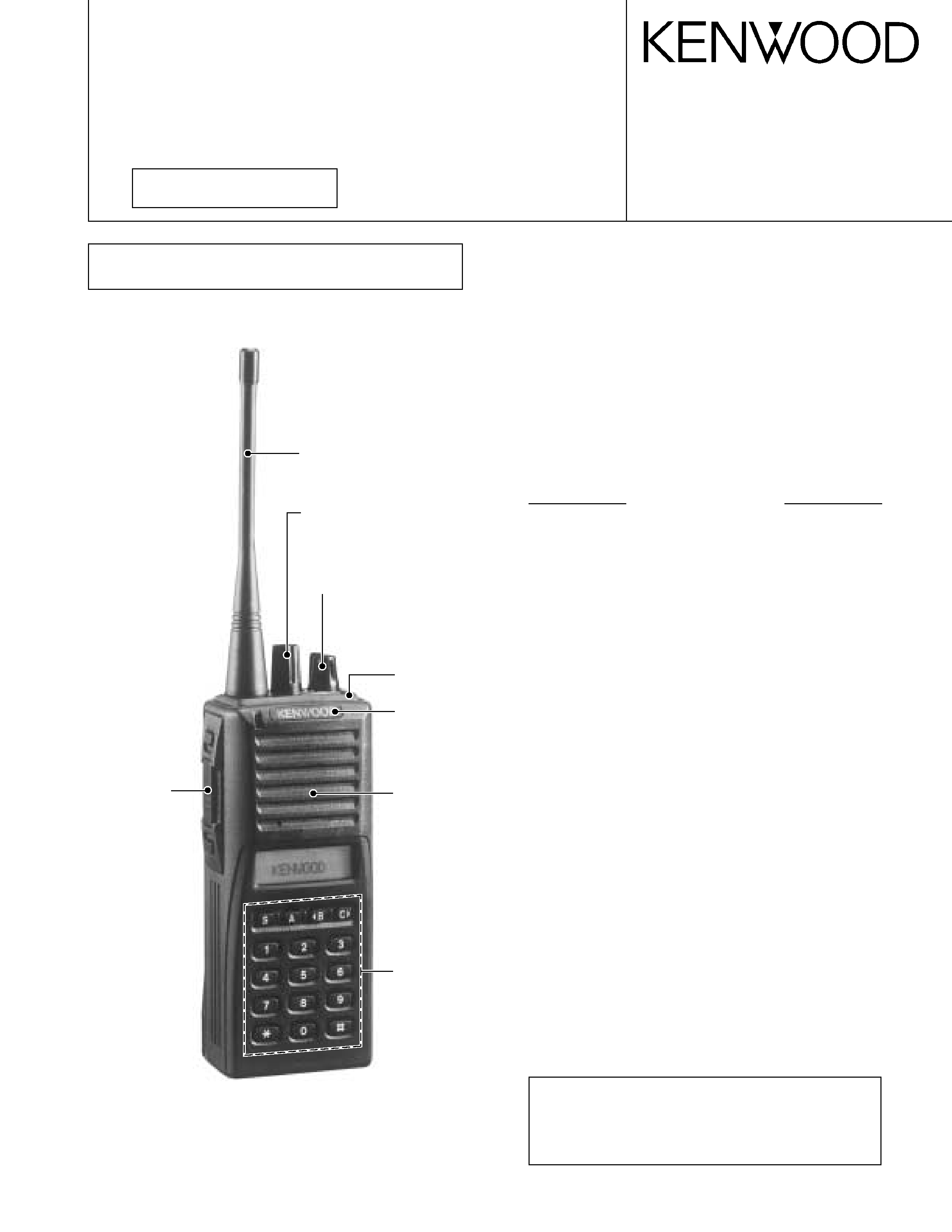
800MHz/900MHz FM TRANSCEIVER
TK-480/481
SERVICE MANUAL
GENERAL ............................................................ 2
SYSTEM SET-UP ................................................ 2
OPERATING FEATURES .................................... 3
REALIGNMENT ................................................. 11
CIRCUIT DESCRIPTION .................................... 14
SEMICONDUCTOR DATA ................................ 20
DESCRIPTION OF COMPONENTS .................. 23
PARTS LIST ....................................................... 24
EXPLODED VIEW ............................................. 30
PACKING ........................................................... 31
ADJUSTMENT .................................................. 32
TERMINAL FUNCTION .................................... 40
PC BOARD VIEWS
DISPLAY UNIT (X54-3210-XX) .................... 41
TX-RX UNIT (X57-5630-XX) ......................... 47
SCHEMATIC DIAGRAM ................................... 53
BLOCK DIAGRAM ............................................. 57
LEVEL DIAGRAM (TK-480) .............................. 59
LEVEL DIAGRAM (TK-481) .............................. 60
KNB-16A/17A (Ni-Cd BATTERY) ..................... 61
KPG-36 (PROGRAMMING INTERFACE CABLE) .... 61
KSC-19 (CHARGER) .......................................... 61
SPECIFICATIONS .............................................. 62
CAUTION
When using an external power connector,
please use with maximum final module pro-
tection of 9V.
CONTENTS
REVISED II
Photo is TK-480/481 K2 type.
(Produced in Singapore)
This service manual applies to products with 30100001 or
subsequent serial numbers.
Knob (PTT)
(K29-5157-03)
Whip antenna
(T90-0636-25) : TK-480
(T90-0640-25) : TK-481
Knob (ENC)
(K29-5232-03)
Knob (VOL)
(K29-5231-03)
Panel assy
(A62-0981-04)
Cabinet assy
(A02-3659-03) : K2
Badge
(B43-1139-04)
Packing
(G53-0841-02) : K2
2
TK-480/481
GENERAL / SYSTEM SET-UP
INTRODUCTION
SCOPE OF THIS MANUAL
This manual is intended for use by experienced techni-
cians familiar with similar types of commercial grade com-
munications equipment. It contains all required service in-
formation for the equipment and is current as of this publica-
tion date. Changes which may occur after publication are
covered by either Service Bulletins or Manual Revisions,
which are issued as required.
ORDERING REPLACEMENT PARTS
When ordering replacement parts or equipment informa-
tion, the full part identification number should be included.
This applies to all parts : components, kits, and chassis. If
the part number is not known, include the chassis or kit
number of which it is a part and a sufficient description of
the required component, for proper identification.
PERSONNEL SAFETY
The following precautions are recommended for person-
nel safety :
· DO NOT transmit until all RF connectors are secure and
any open connectors are properly terminated.
· SHUT OFF this equipment when near electrical blasting
caps or while in an explosive atmosphere.
· This equipment should be serviced by only qualified tech-
nicians.
SERVICE
This radio is designed for easy servicing. Refer to the
schematic diagrams, printed circuit board views, and align-
ment procedures contained within.
NOTE
WE CANNOT guarantee oscillator stability when using
channel elements manufactured by companies other than
KENWOOD or its authorized agents.
You must use the KPG-49D to program TK-480/481 trans-
ceivers with a serial number of 30100001 or greater. You
cannot use the KPG-35D for those radios.
TK-480/481 transceivers with a serial number of
30100001 or greater have a red triangle in the KENWOOD
logo label (B43-1139-04) on the front panel. You will also
find the model name plate marked as "Ver 2.0" on the rear
of the transceiver.
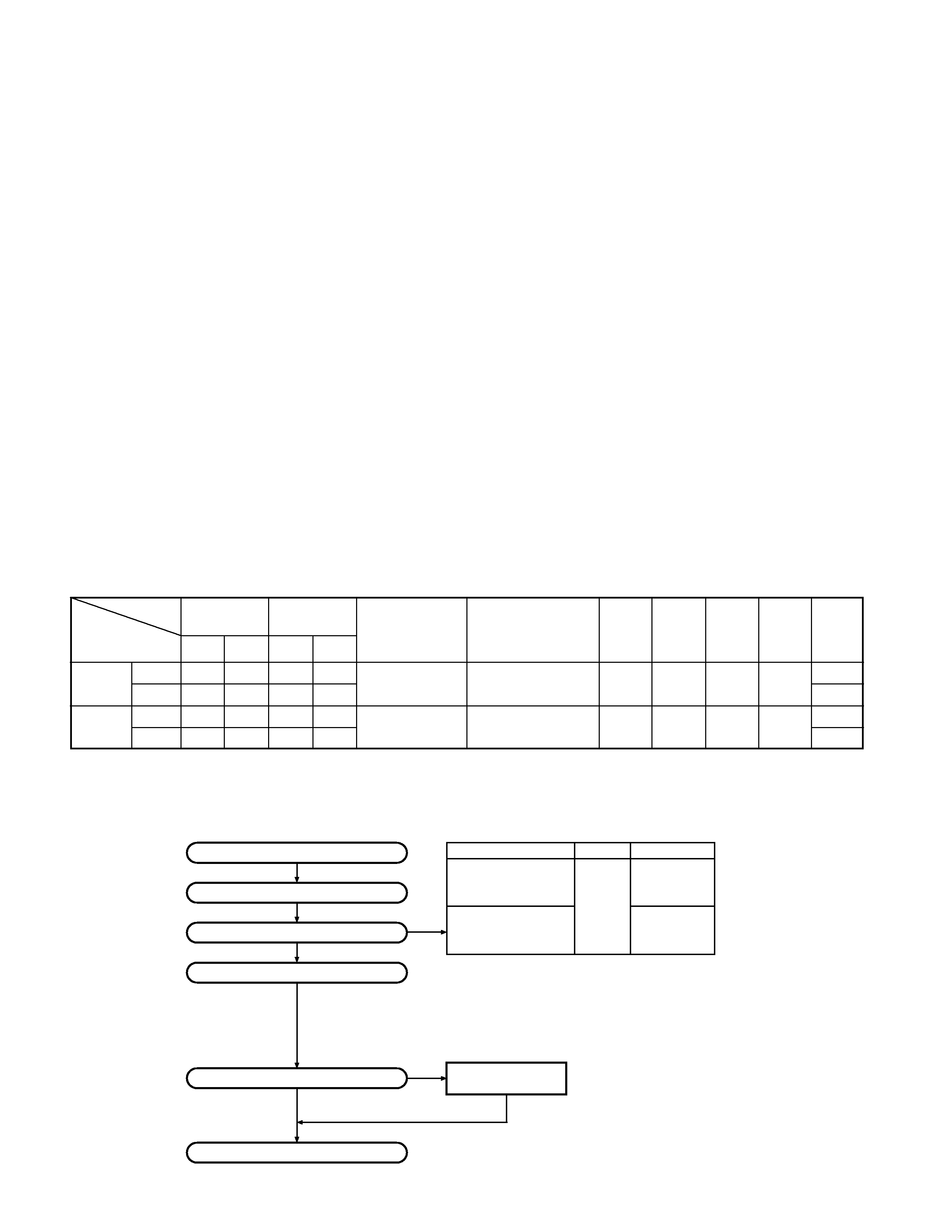
Unit
TX-RX unit
Display unit
Model &
X57-5630-XX
X54-3210-XX
Frequency range
Remarks
QT/DQT
DTMF
Charger Battery
16 key
destination
0-10
0-11
0-10
0-11
TK-480
K
806~870MHz
IF1 : 44.85MHz
Option
K2
LOC : 44.395MHz
TK-481
K
896~941MHz
IF1 : 44.85MHz
Option
K2
LOC : 44.395MHz
Note
X57-5630-XX/X54-3210-XX : Produced in Singapore
Merchandise received
License and frequency allocated by FCC
Choose the type of transceiver
Transceiver programming
Are you using the speaker microphone?
Delivery
TX
806~825
2.5W
TK-480 K,K2
851~870
RX
851~870
TX
896~902
TK-481 K,K2
935~941
RX
935~941
Frequency range (MHz) RF power
Type
A personal computer (IBM PC or compatible), programming
interface (KPG-36), and programming software (KPG-49D) are
required for programming.
(The frequency, trunked system features, conventional system
features, TX power HI/LOW, and signaling data are programmed
for the transceiver.)
YES
NO
KMC-25
Speaker microphone
(Option)
SYSTEM SET-UP
3
TK-480/481
OPERATING FEATURES
1. Operation Features
The TK-480/481 is an 800/900MHz band EFJ LTRTM-com-
patible trunked radio designed to operate in both trunked
and conventional modes. The programmable features are
summarized.
Model
Trunking mode
Conventional mode
This model can handle up to 32 systems with up to 250
groups in each system. The transceiver can be used in both
trunked mode and conventional mode. Systems, groups,
and their functions are programmed.
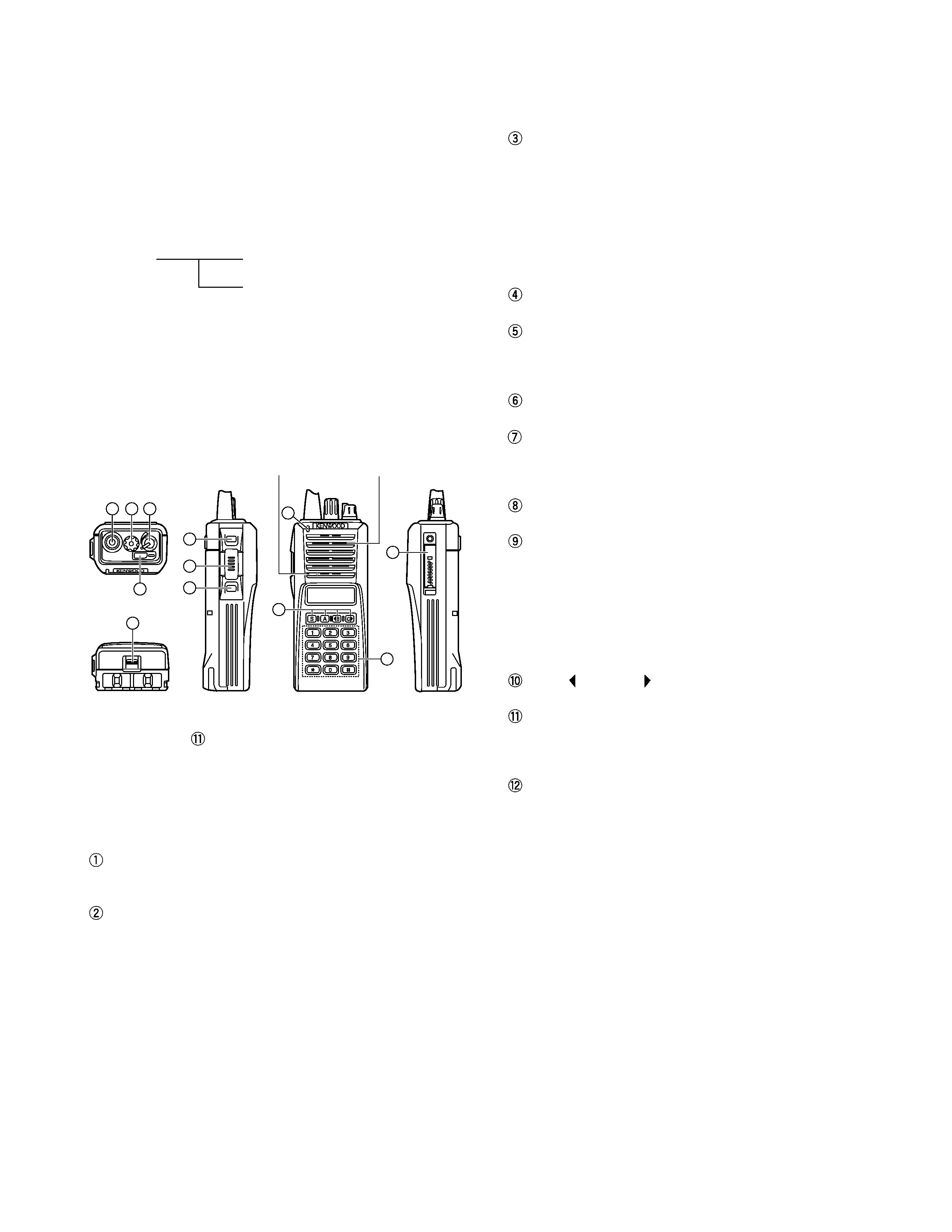
2. Transceiver Controls and Indicators
2-1. Physical Layout
5
4
1
2
3
Microphone
Speaker
6
10
11
12
9
7
8
Note : The transceiver is also available without the DTMF
keypad (
).
2-2. Panel controls
The key on the top and front panel is momentary-type
push buttons. The functions of these keys and knob are ex-
plained below.
Antenna connector
Connect the supplied antenna here.
System or Group selector knob (Programmable)
Turning the system (or group) selector knob clockwise
increases the system (or group) number by one. Turning
the knob in the counterclockwise direction decreases the
system (or group) number by one.
After the system number (or group number) reaches the
highest system number (or group number), it goes back
to lowest system number (or group number).
System numbers (or group numbers) not set are skipped.
Caution : The FPU (KPG-49D) allows selecting between
system selector and group selector.
Volume/Power switch
Transceiver Power and Volume switch. Turn clockwise to
switch On the transceiver. Turn counterclockwise fully to
switch OFF the transceiver. Also adjusts the volume
level. When the power is switched off, all the param-
eters, such as the system and group, are stored in
memory. When the power is switched on again, the sys-
tem returns to the previous conditions.
Auxiliary (orange) key (Programmable)
Battery pack release catch
Push down to release the battery pack. See Installing the
Ni-Cd Battery Pack.
MONITOR key* (Programmable)
PTT (Push-To-Talk) key
Press this key, then speak into the microphone to call a
station.
LAMP key* (Programmable)
TX/BATT indicator
This red LED lights during transmission (it does not light
during busy or when transmit is prohibited). If the battery
voltage falls below the programmed voltage during trans-
mission, the brightness of this indicator decreases at in-
tervals of about one second, so it can be used as the bat-
tery voltage alert function.
S, A,
B, and C
key (Programmable)
DTMF keypad (keypad model only)
Press the keys on the telephone keypad to send DTMF
tones.
Universal connector
Connect the external KMC-25 speaker/ microphone (op-
tional) here. Otherwise, keep the supplied cover in place.
* : MONITOR and LAMP are arbitrary names chosen for
these buttons. They can be used for any of the auxiliary
functions.
2-3. Programmable keys
The FPU (KPG-49D) enables programmable keys to se-
lect the following functions.
Auto Tel, AUX(only when Voice Scrambler is not se-
lected), DTMF ID (BOT), DTMF ID (EOT), Display Character,
Emergency (only AUX key), Function, Group Down, Group
Up, Home Group, Key Lock, Lamp, Memory (RCL/STO),
Memory (RCL), Memory (STO), Monitor A, Monitor B, Moni-
tor C, Monitor D, Redial, RF Power Lo, Scan, Scan Del/Add,
Scan Temporary Delete, Scrambler (Only when Voice
Scrambler is selected), SP Attenuation (Only MIC switch),
System Down, System Up, TEL Disconnect and none.
These functions the FPU programs to the function keys
are described in the following sections.

4
TK-480/481
OPERATING FEATURES
s Auto TEL
Automatically connects available repeaters that are con-
nected to telephone circuits when operating as LTR system.
The time allocated to search for available repeaters is 60
seconds, after which connection failure occurs, a DTMF
tone is output and the function terminates.
If connection to an available circuit is made, only ID 253,
EOT or hang-up time-out can terminate the function.
s AUX
This function can be programmed when the voice scram-
bler board is not installed.
If this key is pressed, an underscore ("_") appears at the
extreme right of the LCD and AUX port which is inside of the
transceiver turns to the active level. If pressed again, the
underscore disappears and the AUX ports turns to the
deactive level.
s DTMF ID (BOT)
Pressing this key in Conventional mode, automatically
sends the preset Connect ID.
s DTMF ID (EOT)
Pressing this key in Conventional mode, automatically
sends the preset Disconnect ID.
s Display character
This key switches the LCD display between the system/
group number and system/group name.
s Emergency
Pressing this key for longer than the programmed "Emer-
gency Key Delay Time" causes the transceiver to enter the
emergency mode. The transceiver jumps to the pro-
grammed "Emergency System/Group" and transmits for
the programmed "Active Time".
The transceiver disables mic mute while transmitting.
After finishing transmission, the transceiver receivers for
the programmed "Interval Time". The transceiver mutes
the speaker while receiving. Following the above sequence,
the transceiver continues to transmit and receive.
If "Man Down Switch" has been programmed on the ra-
dio and the switch is activated, the radio enters Emergency
mode after the specified "Man Down Delay Time" expires.
s Function
Pressing this key causes the transceiver to display
"FCN". Then, pressing a DTMF key causes the correspond-
ing programmed function to start. This key may be conve-
nient when using many functions with the 12-key keypad
(K2 type).
s Group up/down
When the key is pressed each time, the group number to
be selected is incremented/decremented and repeats if held
for one second or longer.
s Home group
Each pressing of the key selects a preset system/group.
s Key lock
Pressing this key causes the transceiver to accept entry
of only the [Function], [Key Lock], [PTT], [Lamp], [Monitor A],
[Monitor B], [Monitor C], [Monitor D], and [Emergency] keys.
The locked keys also include the tuning control.
s Lamp
This key illuminates the LCD and keys on the front panel.
When the key is pressed, the LED lamp goes on.
When it is released, the lamp goes off after about five
seconds. If any key is pressed while the LED lamp is on, the
lamp is kept on for five seconds.
s Memory
This key allows DTMF memory data to be recalled; up to
32 memories each with a memory dial of up to 16 digits and
an A/N of up to 10 digits per memory.
s Monitor
Used to release signalling or squelch when operating as a
conventional. It is also used to reset option signalling.
s Redial
Pressing this key when System/Group is shown, displays
the previously transmitted DTMF code. Pressing [PTT] at
this time, transmits the code that is currently displayed.
s RF power low
Used to temporarily switch transmission output to low
power. Turning the function on enables:
Hi
Low, LowLow
Key states are backed up, except in the PC mode when
they are reset.
s Scan
Press this key starts scanning. Pressing this key stops
scanning.
s Scan Del/Add
Used to select whether system scan routines are used
during system scan. Each pressing of the key (to ON)
toggles between lockout and lock. The scan routine is
started when on lock. The DEL indicator flashes when the
system is on lockout.
s Scan temporary delete
This key is temporarily deleted a system being scanned.
If you press this key when scan is stopped (when a call is
being received from another station), the system is tempo-
rarily deleted and scanning restarts.
This key operates even when "Scan Type" is set to "List
Type System Scan".
s Scrambler
If a scrambler code (1 to 4) has been set in the FPU, an
underscore ("_") appears at the extreme right of the LCD
display when scrambler is active. Pressing this key changes
ON/OFF of scramble operation.
Holding this key down for 2 seconds sets Scramble Code
Select Mode.
5
TK-480/481
OPERATING FEATURES
s System up/down
When the key is pressed each time, the system number
to be selected is incremented/decremented and repeats if
held for one second or longer.
s Telephone disconnect
Pressing this key ends an RIC connection (disconnects
the telephone line).
s None
Sounds error operation beep, and no action will occur.
Use this function when the transceiver is required to be
more simple operated.
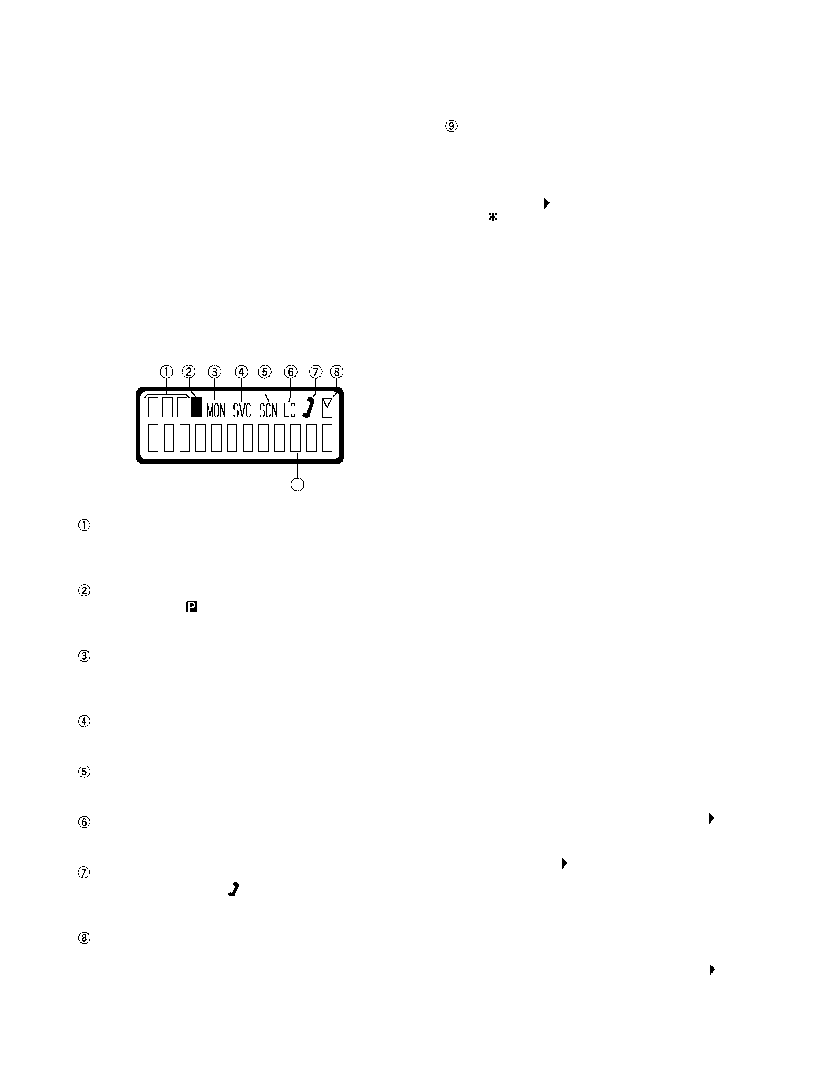
2-4. Display
Alphanumeric display
The twelve-character dot matrix alphanumeric display
shows the system and group numbers. You can program
system and group names with up to ten characters in
place of these numbers. The left display is used as a de-
lete indicator (
) and the right is used for the selective
call (
) or scrambler ( _ ) function. The delete/add indica-
tor shows the systems locked out of the scanning se-
quence. Selective call and scrambler are optional func-
tions that can be programmed.
3. Scan Operating
3-1. System scan
System scan can be selected with the "Scan" key by pro-
gramming the scan feature. When the "Scan" key is
pressed and the "SCN"' mark appears, scan mode in en-
tered. Scanning starts from the system following the cur-
rently displayed system. When a call is received, scanning
stops, and the system and group are displayed.
When the system knob or programming key is touched
during scanning, the scan stops and the revert system or
group can be changed. Scanning resumes one second after
the key is released.
System scan consists of the following 2 types.
s Fix system scan
All the set systems except locked-out ones are scanned.
If the DEL/ADD feature is assigned to the programmable
key, it can be controlled from the front panel.
s List type system scan
A scan list can be set for each system.
The list to be scanned can be changed by changing the
display system.
If many system have been set, the scan speed can be
increased by narrowing the systems to be scanned with
scan lists.
3-2. System lockout
The system lockout feature is used to lock systems out
of the scan sequence, and can be selected by programming
in the following two ways:
s Fixed lockout
The system to be locked out is selected by programming.
When a locked system is selected, the Delete (
) indicator
appears on the left of the SYSTEM indicator. The revert sys-
tem is scanned even if it is locked out. If there is a locked
system, the Delete (
) indicator flashes during fixed scan-
ning.
s User selectable lockout
If the scan lockout feature is programmed to a key, the
user can lock systems out of the scan sequence with the
key. To lock a system out of the scan sequence, press the
key when the system is displayed. The Delete (
) indicator
is displayed on the left of the SYSTEM indicator.
Sub display
Displays the system, channel and group numbers. Also
displays various functions, such as TA.
P (Priority) indicator
The P indicator (
) appears when a selected channel is
programmed as priority, in conventional operation.
MON (Monitor) indicator
The MON indicator appears when the button pro-
grammed as MONITOR is pressed.
SVC (Service) indicator
This icon is not used on this transceiver.
SCN (Scan) indicator
The SCN indicator appears when using Scan mode.
LO indicator
Appears when low power is selected.
Handset indicator
The handset indicator (
) appears when the selected
group is programmed as telephone IDs.
MAIL indicator
Flashes when a status message (FleetSyncTM) is re-
ceived. Lights when a status message is stored in the
stack memory.
P
9