UHF FM TRANSCEIVER /
UHF FM
TK-388G
© 2002-10 PRINTED IN JAPAN
B51-8635-00 (S) 607
SERVICE MANUAL /
GENERAL ............................................................. 2
SYSTEM SET-UP ................................................. 3
OPERATING FEATURES ..................................... 4
REALIGNMENT .................................................. 13
DISASSEMBLY FOR REPAIR ............................ 28
CIRCUIT DESCRIPTION ..................................... 29
SEMICONDUCTOR DATA ................................. 37
COMPONENTS DESCRIPTION ......................... 40
PARTS LIST ........................................................ 42
EXPLODED VIEW ............................................... 48
PACKING ............................................................ 49
ADJUSTMENT ................................................... 50
PC BOARD
DISPLAY UNIT (X54-3250-10) ...................... 65
TX-RX UNIT (X57-6500-21) .......................... 67
SCHEMATIC DIAGRAM ..................................... 73
BLOCK DIAGRAM .............................................. 77
LEVEL DIAGRAM ............................................... 79
KNB-14/KNB-15A (Ni-Cd BATTERY) ................ 80
KMC-17/KMC-21 (SPEAKER MICROPHONE) .. 81
SPECIFICATIONS ............................ BACK COVER
CONTENTS
M6 VERSION
Helical antenna
(T90-0735-05)
Knob
(ENCODER)
(K29-5331-03)
Knob (VOLUME)
(K29-5332-03)
Cabinet assy
(A02-2385-53)
Button knob
(PTT)
(K29-5334-23)
Key top (DTMF)
(K29-5459-12)
Button knob
(MONI/LAMP)
(K29-5333-13)

TK-388G
2
GENERAL /
INTRODUCTION
SCOPE OF THIS MANUAL
This manual is intended for use by experienced technicians
familiar with similar types of commercial grade
communications equipment. It contains all required service
information for the equipment and is current as of the
publication date. Changes which may occur after publication
are covered by either Service Bulletins or Manual Revisions.
These are issued as required.
ORDERING REPLACEMENT PARTS
When ordering replacement parts or equipment
information, the full part identification number should be
included. This applies to all parts, components, kits, or chassis.
If the part number is not known, include the chassis or kit
number of which it is a part, and a sufficient description of
the required component for proper identification.
PERSONNEL SAFETY
The following precautions are recommended for personnel
safety:
DO NOT transmit until all RF connectors are verified secure
and any open connectors are properly terminated.
SHUT OFF and DO NOT operate this equipment near
electrical blasting caps or in an explosive atmosphere.
This equipment should be serviced by a qualified technician
only.
............................................................................................... 2
...................................................................................... 3
...................................................................................... 4
.................................................................................... 13
....................................................................... 28
.................................................................................... 29
................................................................................ 37
.................................................................................... 40
........................................................................................ 42
................................................................................ 48
............................................................................................. 49
............................................................................................. 50
PC
(X54-3250-10) .................................................... 65
TX-RX (X57-6500-21) ............................................... 67
........................................................................................ 73
........................................................................................ 77
........................................................................................ 79
KNB-14/KNB-15A () ............................................ 80
KMC-17/KMC-21 () .............................................. 81
............................................................................................. 83
TK-388G
3
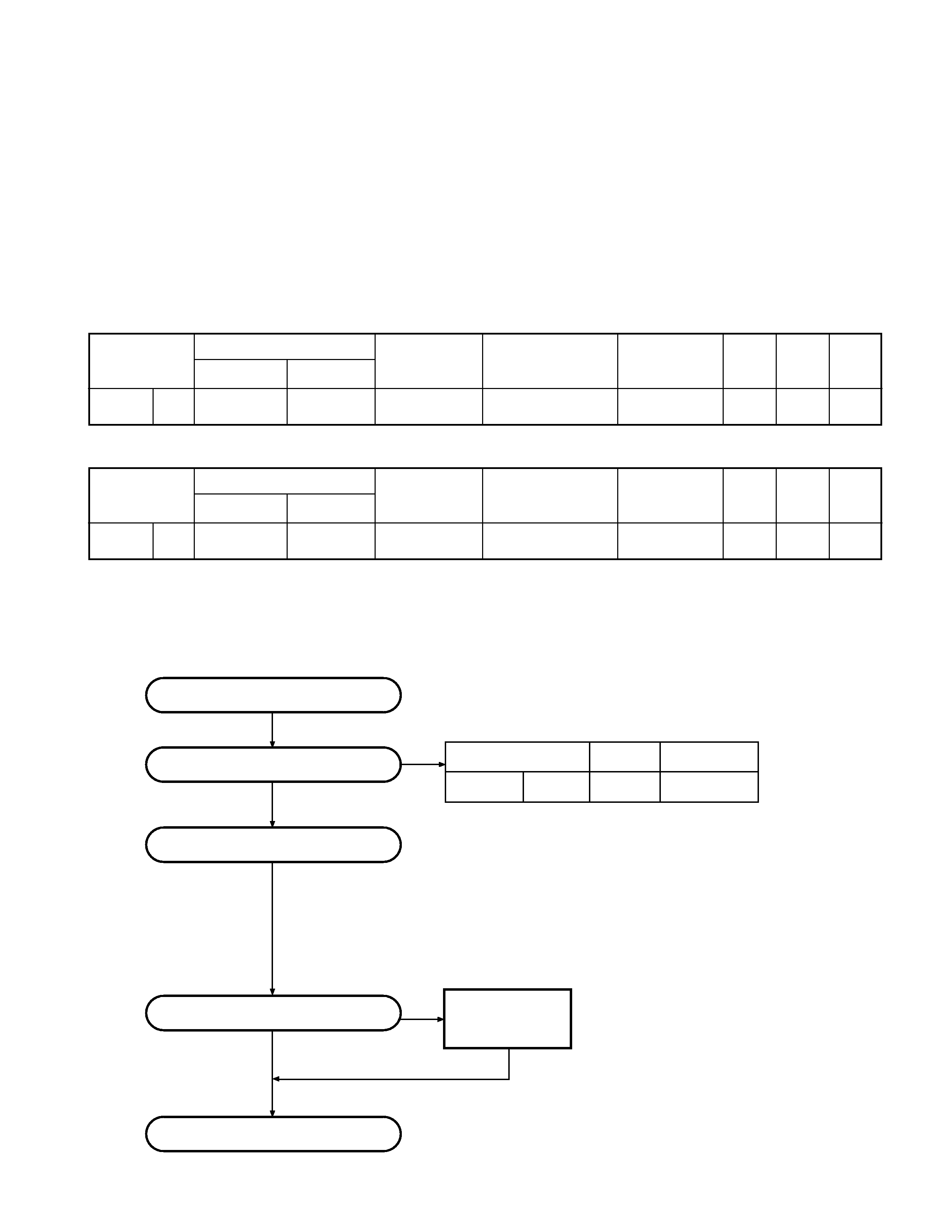
SYSTEM SET-UP /
Merchandise received
Choose the type of transceiver
Transceiver programming
Delivery
Are you using the speaker microphone?
TX/RX
4.0W
TK-388G M6
Frequency range (MHz) RF power
Type
A personal computer (IBM PC or compatible), programming
interface (KPG-22), and programming software (KPG-56D ver 3.30 or later)
are required for programming.
(The frequency, TX power HI/LOW, and signalling data are programmed
for the transceiver.)
YES
NO
KMC-17 or KMC-21
Speaker microphone
(Option)
IBMKPG-22
KPG-56D 3.30
/
MHz
KMC-17KMC-21
350~370
SERVICE
This radio is designed for easy servicing. Refer to the
schematic diagrams, printed circuit board views, and
alignment procedures contained within.
Note:
You must use KPG-56D version 3.30 or later for this
transceiver. KPG-56D versions 3.20 or earlier do not work
properly.
SYSTEM SET-UP /
KPG-56D 3.30KPG-
56D 3.20
16
TX-RX
TK-388G
IF1 : 49.95MHz
M6
X57-6500-21
X54-3250-10
350~370MHz
LOC : 50.4MHz
Unit
Model &
Frequency range
Remarks
HELICAL Antenna Charger Battery
16 Key
destination
TX-RX Unit
Display Unit
IF1 : 49.95MHz
TK-388G
M6
X57-6500-21
X54-3250-10
350~370MHz
LOC : 50.4MHz
Option
Option
TK-388G
4
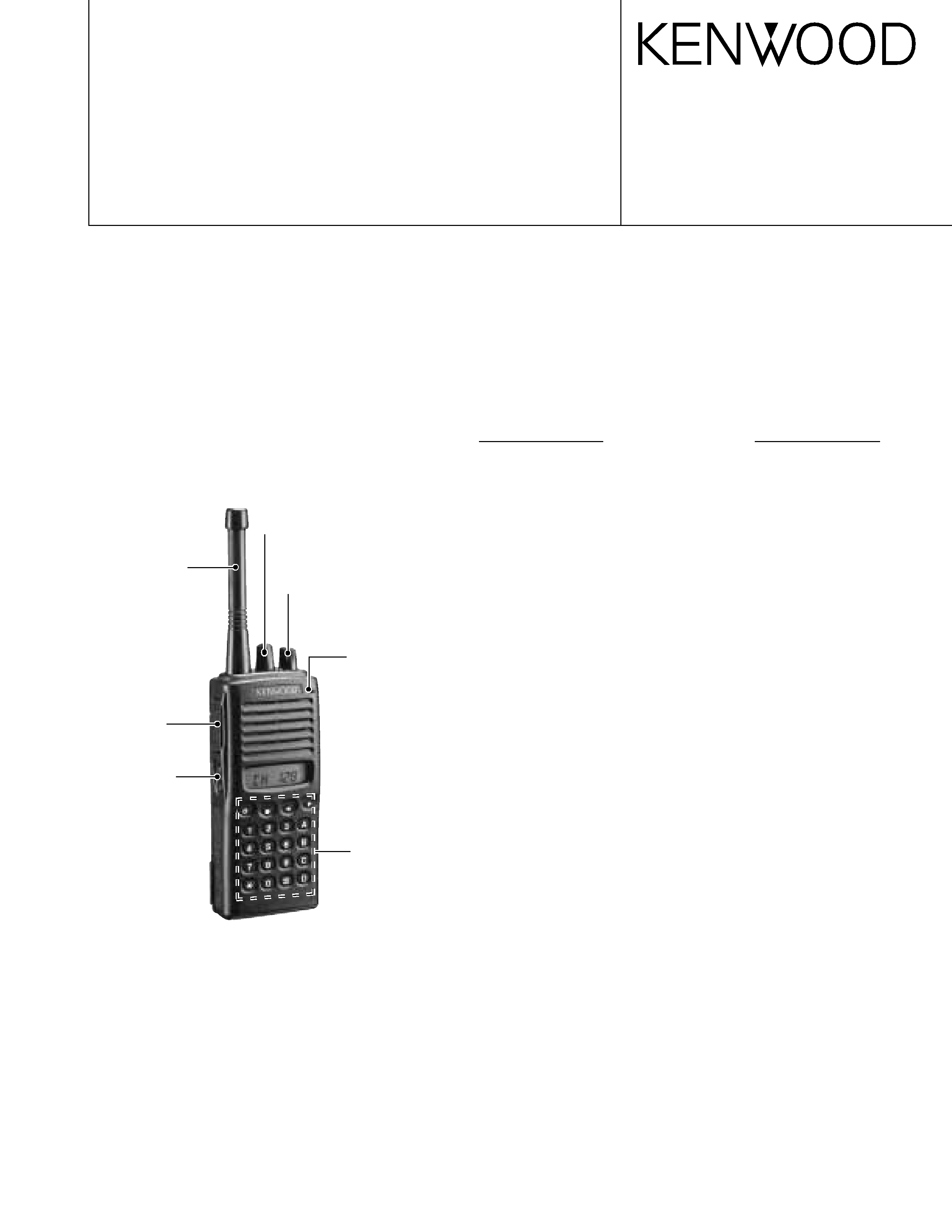
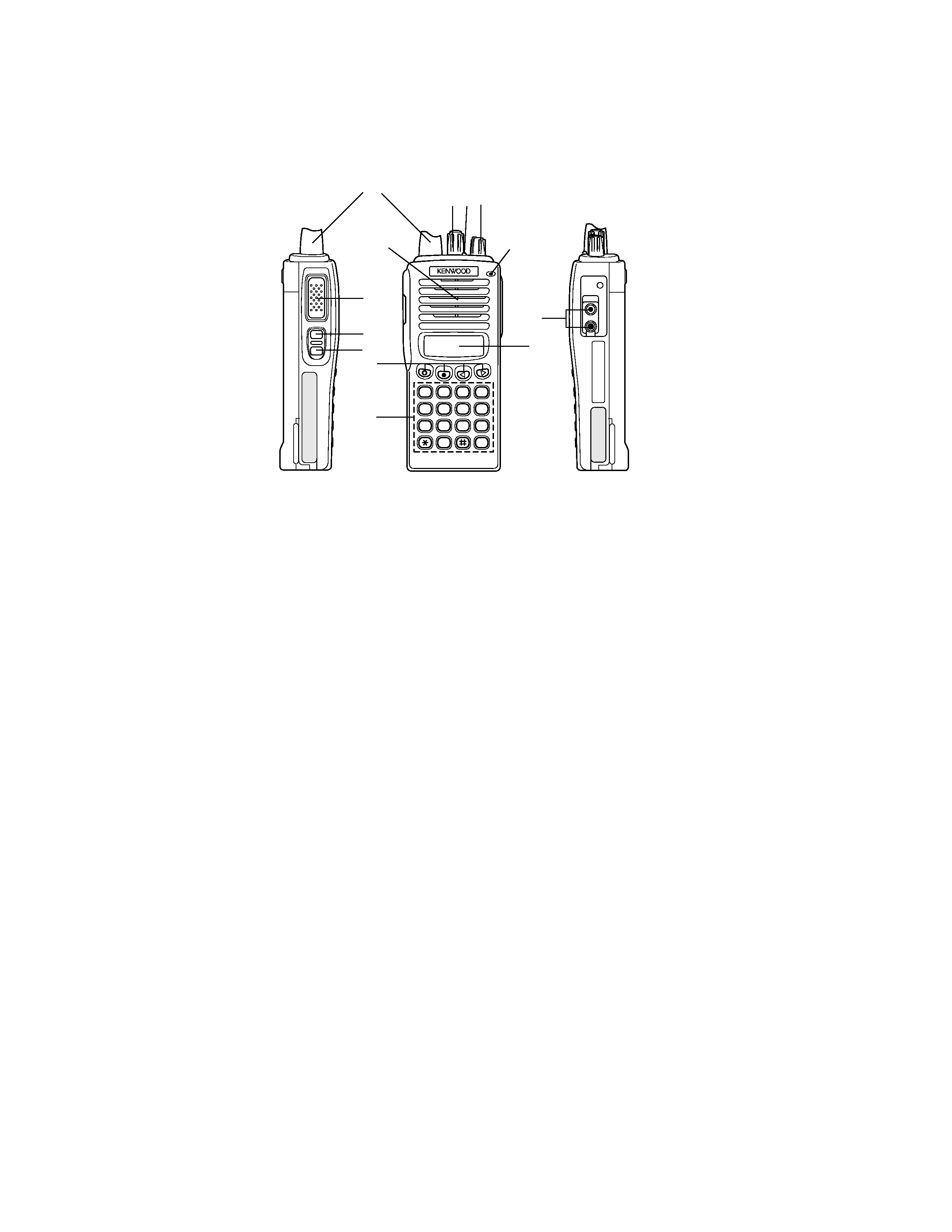
OPERATING FEATURES /
1. Operation Features
1.
The transceiver is shown with the optional KNB-14 battery pack.
q
q
q
q
q Rotary encoder
Your dealer can program the encoder as either Group
Up/Down or Channel Up/Down (default setting). Rotate
to select a group or channel. Also rotate to adjust the
squelch in Squelch Adjustment mode.
w
w
w
w
w LED indicator
Lights red while transmitting. Lights green while
receiving. Flashes orange while receiving a Code
Squelch or a Selective Call code, or a 2-Tone or DTMF
signal that matches the one set up in your transceiver.
Flashes red when the battery power is low while
transmitting.
e
e
e
e
e Power switch/ Volume control
Turn clockwise to switch ON the transceiver. Rotate to
adjust the volume. To switch OFF the transceiver, turn
counterclockwise fully.
r
r
r
r
r PTT (Push-to-Talk) switch
Press this switch, then speak into the microphone to
call a station.
t
t
t
t
t Side 1 key
This is a PF (Programmable Function) key. Press it to
activate its auxiliary function (page 5).
y
y
y
y
y Side 2 key
This is a PF (Programmable Function) key. Press it to
activate its auxiliary function (page 5).
u
u
u
u
u °, ·,
2
2
2
2
2,3
3
3
3
3 keys
These are PF (Programmable Function) keys. Press
each key to activate its auxiliary function.
i
i
i
i
i DTMF keypad
Used for storing and transmitting DTMF numbers.
o
o
o
o
o SP/MIC jacks
Connect an optional speaker/ microphone here.
!0
!0
!0
!0
!0 Display
(See page 7.)
KNB-14
q
q
q
q
q
/
/
w
w
w
w
w
DTMF
e
e
e
e
e
/
r
r
r
r
r
PTT
t
t
t
t
t
PF
5
y
y
y
y
y
PF
5
u
u
u
u
u °
·2222233333
PF
i
i
i
i
i
DTMF
DTMF
o
o
o
o
o
/
/
!0
!0
!0
!0
!0
7
Antenna
A
3
2
1
B
6
5
4
C
9
8
7
D
0
q
q
q
q
q
e
e
e
e
e
r
r
r
r
r
t
t
t
t
t
y
y
y
y
y
u
u
u
u
u
i
i
i
i
i
o
o
o
o
o
!0
!0
!0
!0
!0
w
w
w
w
w
Microphone
Speaker

TK-388G
5
·
·
A
· °
·
· /
·
2
2
2
2
2
·
3
3
3
3
3
°·
2
2
2
2
2 3
3
3
3
3
·
·
·
·
·
·
·
·
·
A -
·
B -
·
C -
·
D -
·
·
·
·
·
/
·
QT
·
·
·
SmarTrunkII®*1
*1
Programmable Auxiliary Functions
Side 1, Side 2,
°, ·,
2
2
2
2
2, and 3
3
3
3
3 can be programmed with
the auxiliary functions listed below.
· Channel Down
· Channel Up
· Display Character
· Group Down
· Group Up
· Home Channel
· Key Lock
· Lamp
· Monitor A (Monitor UnmuteMomentary)
· Monitor B (Monitor UnmuteToggle)
· Monitor C (Carrier SquelchMomentary)
· Monitor D (Carrier SquelchToggle)
· None
· Redial
· RF Power Lo
· Scan
· Scan Del/Add
· Selectable QT
·Talk Around
· 2-Tone Encode Select
·Trunking Group Code Select *1
*1 Available only when using Trunking function.
2. Programmable keys
The functions the FPU programs to the function keys are
described in the following sections.
1) Channel up/down
When the key is pressed each time, the channel number
to be selected is incremented/decremented and repeats
if held for one second or longer.
This key functions as the voice scrambler code selector in
the voice scrambler code select mode.
2) Display character
This key switches the LCD display between the group/
channel number and group/channel name.
3) Group up/down
When the key is pressed each time, the group number to
be selected is incremented/decremented and repeats if
held for one second or longer.
2
FPU
1 /
1
/
2
LCD / /
3 /
1
/
Note: The PF keys are programmed with default functions:
·
Side 1 key: Lamp
·
Side 2 key: Monitor A
· °
key:
Scan
·
· key:
Scan Del/Add
·
2
2
2
2
2 key:
Talk Around
·
3
3
3
3
3 key:
RF Power Lo
OPERATING FEATURES /