UHF FM TRANSCEIVER
TK-373G
© 2002-1 PRINTED IN JAPAN
B51-8618-00 (S) 931
SERVICE MANUAL
GENERAL ...................................................................... 2
SYSTEM SET-UP .......................................................... 2
OPERATING FEATURES .............................................. 3
REALIGNMENT ............................................................. 7
DISASSEMBLY FOR REPAIR ..................................... 10
CIRCUIT DESCRIPTION ............................................. 11
SEMICONDUCTOR DATA .......................................... 15
DESCRIPTION OF COMPONENTS ............................ 16
PARTS LIST ................................................................. 18
EXPLODED VIEW ....................................................... 25
PACKING ..................................................................... 26
CONTENTS
ADJUSTMENT ............................................................. 27
PC BOARD VIEWS
DISPLAY UNIT (X54-3250-11) ............................... 37
TX-RX UNIT (X57-650X-XX) .................................. 39
SCHEMATIC DIAGRAM .............................................. 45
BLOCK DIAGRAM ....................................................... 49
LEVEL DIAGRAM ........................................................ 51
KNB-14/KNB-15A (Ni-Cd BATTERY) .......................... 52
KNB-20N (Ni-MH BATTERY) ....................................... 52
KMC-17/KMC-21 (SPEAKER MICROPHONE) ............ 53
SPECIFICATIONS ................................... BACK COVER
Knob (ENCODER)
(K29-5331-03)
Knob (VOLUME)
(K29-5332-03)
Cabinet assy
(A02-3568-33)
Button knob (PTT)
(K29-5334-13)
Key top (4 keys)
(K29-9142-02)
Button knob
(MONI/LAMP)
(K29-5333-13)
TK-373G
2
Unit
Model &
TX-RX Unit
Display Unit
Frequency range
Remarks
destination
K
X57-6500-10
450~470MHz
IF1 : 49.95MHz
TK-373G
K2
X57-6500-11
X54-3250-11
470~490MHz
LOC : 50.4MHz
GENERAL / SYSTEM SET-UP
INTRODUCTION
SCOPE OF THIS MANUAL
This manual is intended for use by experienced technicians
familiar with similar types of commercial grade
communications equipment. It contains all required service
information for the equipment and is current as of the
publication date. Changes which may occur after publication
are covered by either Service Bulletins or Manual Revisions.
These are issued as required.
ORDERING REPLACEMENT PARTS
When ordering replacement parts or equipment
information, the full part identification number should be
included. This applies to all parts, components, kits, or chassis.
If the part number is not known, include the chassis or kit
number of which it is a part, and a sufficient description of the
required component for proper identification.
PERSONNEL SAFETY
The following precautions are recommended for personnel
safety:
q
DO NOT transmit until all RF connectors are verified secure
and any open connectors are properly terminated.
q
SHUT OFF and DO NOT operate this equipment near
electrical blasting caps or in an explosive atmosphere.
q
This equipment should be serviced by a qualified technician only.
SERVICE
This radio is designed for easy servicing. Refer to the
schematic diagrams, printed circuit board views, and alignment
procedures contained within.
SYSTEM SET-UP
Merchandise received
License and frequency allocated by FCC
Choose the type of transceiver
Transceiver programming
Are you using the optional antenna?
A personal computer (IBM PC or compatible), programming interface (KPG-22),
and programming software (KPG-76D) are required for programming.
(The frequency, TX power HI/LOW, and signalling data are programmed for the transceiver.)
YES
NO
KRA-15
Whip antenna
(Option)
Delivery
Are you using the speaker microphone?
YES
NO
KMC-17 or KMC-21
Speaker microphone
(Option)
TX/RX 470~490
TK-373G K2
Frequency range (MHz)
RF power
Type
4.0W
TX/RX 450~470
4.0W
TK-373G K
TK-373G
3
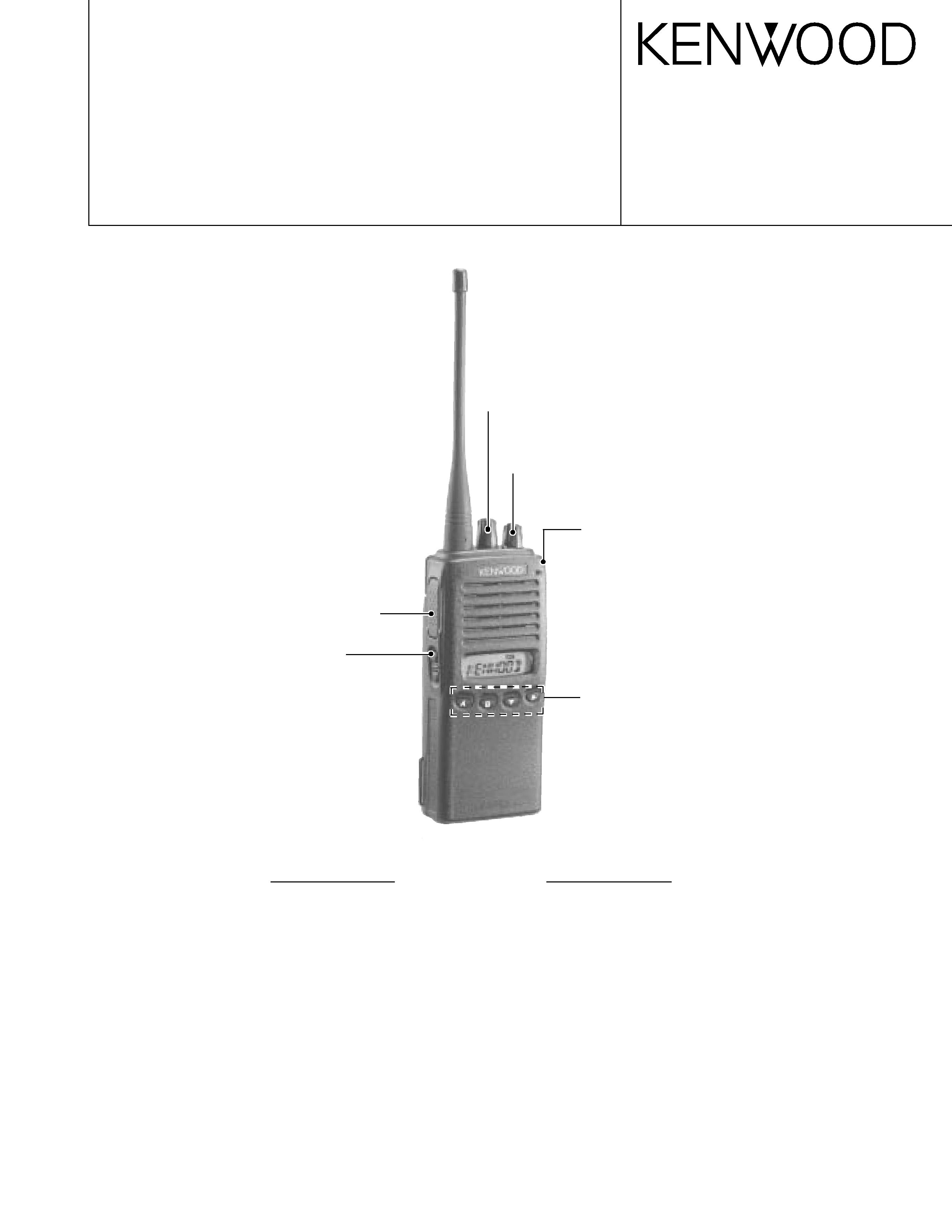
OPERATING FEATURES
1. Operating Features
The transceiver is shown with the optional KNB-14 battery pack.
q
q
q
q
q Rotary encoder
Your dealer can program the encoder as either
System Up/Down or Group Up/Down. Rotate to
select a system or group.
w
w
w
w
w Transmit/ Battery low indicator
This red LED lights dur ing transmission.
If
programmed by your dealer, when the battery pack
power is low, the LED flashes during transmission.
Replace or recharge the battery pack at such a time.
e
e
e
e
e Power switch/ Volume control
Turn clockwise to switch ON the transceiver. Rotate
to adjust the volume. To switch OFF the transceiver,
turn counterclockwise fully.
r
r
r
r
r PTT (Push-to-Talk) switch
Press this switch, then speak into the microphone to
call a station.
t
t
t
t
t Side 1 key
This is a PF (Programmable Function) key.
y
y
y
y
y Side 2 key
This is a PF (Programmable Function) key.
u
u
u
u
u A, B,
,5
5
5
5
5 keys
These are PF (Programmable Function) keys.
i
i
i
i
i Speaker /Microphone jacks
Connect an optional speaker/ microphone here.
o
o
o
o
o Display
Note: The PF keys are programmed with default functions:
·
Side 1 key: Lamp
·
Side 2 key: Squelch Off Momentary
·
A key:
None
·
B key:
None
·
key:
Group Down
·
5
5
5
5
5 key:
Group Up
q
q
q
q
q
e
e
e
e
e
r
r
r
r
r
t
t
t
t
t
y
y
y
y
y
u
u
u
u
u
i
i
i
i
i
w
w
w
w
w
Antenna
Microphone
Speaker
o
o
o
o
o
Programmable Auxiliary Functions
You can program the Side 1, Side 2, A, B,
, and 5
5
5
5
5 keys
with the functions listed below.
·Aux
· Display Character
· DTMF ID (BOT)
· DTMF ID (EOT)
· Group Down
· Group Up
· Home Group
· Key Lock
· Lamp
· Memory (RCL)
· Memory (RCL/STO)
· Memory (STO)
· Monitor Momentary
· Monitor Toggle
· None (No function)
· Redial
· RF Power Low
· Scan
· Scan Del/Add
· Scan Temporary Delete
· Squelch Off Momentary
· Squelch Off Toggle
· System Down
· System Up
· Telephone Disconnect
Display
n
o
c
I
n
o
i
t
p
i
r
c
s
e
D
s
i
p
u
o
r
g
d
e
t
c
e
l
e
s
e
h
t
n
e
h
w
s
r
a
e
p
p
A
.
y
ti
r
o
ir
p
s
a
d
e
m
m
a
r
g
o
r
p
s
i
p
u
o
r
g
d
e
t
c
e
l
e
s
e
h
t
n
e
h
w
s
r
a
e
p
p
A
.
d
n
u
o
r
A
k
l
a
T
s
a
d
e
m
m
a
r
g
o
r
p
s
a
d
e
m
m
a
r
g
o
r
p
y
e
k
e
h
t
n
e
h
w
s
r
a
e
p
p
A
r
o
t
i
n
o
M
.
d
e
s
s
e
r
p
s
i
s
r
a
e
p
p
a
,r
e
l
a
e
d
r
u
o
y
y
b
d
e
m
m
a
r
g
o
r
p
fI
.
D
I
n
a
e
v
i
e
c
e
r
u
o
y
n
e
h
w
.
e
d
o
m
n
a
c
S
g
n
i
s
u
e
r
a
u
o
y
n
e
h
w
s
r
a
e
p
p
A
e
h
t
n
o
r
e
w
o
p
w
o
l
g
n
i
s
u
n
e
h
w
s
r
a
e
p
p
A
.
p
u
o
r
g
d
e
t
c
e
l
e
s
e
h
t
n
e
h
w
s
r
a
e
p
p
a
,
n
o
it
a
r
e
p
o
d
e
k
n
u
rt
n
I
s
a
d
e
m
m
a
r
g
o
r
p
s
i
p
u
o
r
g
d
e
t
c
e
l
e
s
.
s
D
I
e
n
o
h
p
e
l
e
t
s
i
d
e
t
c
e
l
e
s
e
h
t
n
e
h
w
s
r
a
e
p
p
A
.
e
c
n
e
u
q
e
s
g
n
i
n
n
a
c
s
e
h
t
m
o
rf
d
e
v
o
m
e
r
.
s
r
e
b
m
u
n
p
u
o
r
g
d
n
a
m
e
t
s
y
s
e
h
t
s
y
a
l
p
s
i
D
d
n
a
m
e
t
s
y
s
m
a
r
g
o
r
p
n
a
c
r
e
l
a
e
d
r
u
o
Y
n
i
,
s
r
e
t
c
a
r
a
h
c
8
o
t
p
u
h
ti
w
s
e
m
a
n
p
u
o
r
g
s
r
e
b
m
u
n
f
o
e
c
a
l
p
m
e
t
s
y
s

TK-373G
4
OPERATING FEATURES
2. Programmable keys
The functions the FPU programs to the function keys are
described in the following sections.
1) AUX
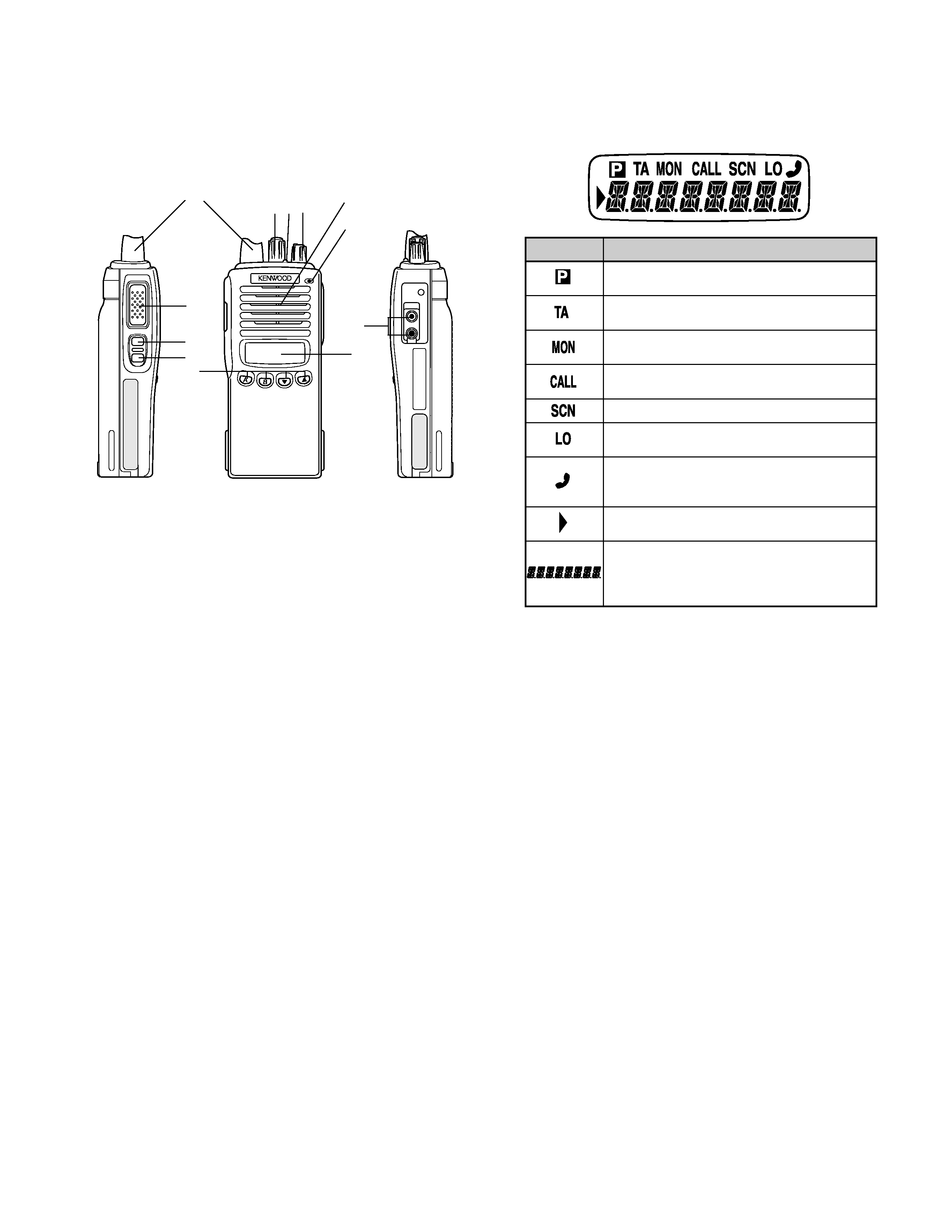
If this key is pressed, a dot appears at the extreme right of
the LCD and AUX port which is inside of the transceiver
turns to the active level. If pressed again, the dot disappears
and the AUX ports turns to the deactive level.
2) Display character
This key switches the LCD display between the system/
group number and system/group name.
3) DTMF ID (Begin of TX)
Pressing this key in Conventional mode, automatically sends
the preset DTMF ID (Begin of TX).
4) DTMF ID (End of TX)
Pressing this key in Conventional mode, automatically sends
the preset DTMF ID (End of TX).
5) Group up/down
When the key is pressed each time, the group number to
be selected is incremented/decremented and repeats if held
for one second or longer.
6) Home group
Each pressing of the key selects a preset system/group.
7) Key lock
Pressing this key causes the transceiver to accept entry of
only the [Monitor Toggle], [Key Lock], [PTT], [Lamp], [Monitor
Momentary], [Squelch off Momentary], and [Squelch off
Toggle] keys.
8) Lamp
This key illuminates the LCD and keys on the front panel.
When the key is pressed, the LED lamp goes on.
When it is released, the lamp goes off after about five
seconds. If any key is pressed while the LED lamp is on,
the lamp is kept on for five seconds.
9) Memory
This key allows DTMF memory data to be recalled; up to 32
memories each with a memory dial of up to 16 digits
and an A/N of up to 8 digits per memory.
10) None
An error operation beep sounds, and no action will occur.
Use this function when the transceiver is required to be
operated more simply.
11) Redial
Pressing this key when System/Group is shown, displays
the previously transmitted DTMF code. Pressing [PTT] at
this time, transmits the code that is currently displayed.
12) RF power low
Used to temporarily switch transmission output to low power.
Turning the function on enables:
Hi
Low, LowLow
Key states are backed up, except in the PC mode when
they are reset.
13) Scan
Pressing this key starts scanning. Pressing this key again
stops scanning.
14) Scan Del/Add
Used to select whether system scan routines are used during
system scan. Each pressing of the key (to ON) toggles
between lockout and lock. The scan routine is started when
on lock. The DEL indicator flashes when the system is on
lockout.
15) Scan temporary delete
This key is temporarily deleted a system being scanned. If
you press this key when scan is stopped (when a call is
being received from another station), the system is
temporarily deleted and scanning restarts.
This key operates even when "Scan Type" is set to "List
Type System Scan".
16) Squelch off
Used to release signalling or squelch when operating in
conventional mode.
17) System up/down
When the key is pressed each time, the system number to
be selected is incremented/decremented and repeats if held
for one second or longer.
18) Telephone disconnect
Pressing this key ends an RIC connection (disconnects the
telephone line).
3. Scan Operating
1) System scan
System scan can be selected with the "Scan" key by
programming the scan feature. When the "Scan" key is pressed
and the "SCN"' mark appears, scan mode in entered. Scanning
starts from the system following the currently displayed system.
When a call is received, scanning stops, and the system and
group are displayed.
When the system knob or programming key is touched
during scanning, the scan stops and the revert system or group
can be changed. Scanning resumes one second after the key
is released.
System Scan consists of the following 2 types.
q
Fix system scan
All the set systems except locked-out ones are scanned. If
the DEL/ADD feature is assigned to the programmable key, it
can be controlled from the front panel.

TK-373G
5
OPERATING FEATURES
q
List type system scan
A scan list can be set for each system.
The list to be scanned can be changed by changing the
display system
If many system have been set, the scan speed can be
increased by narrowing the systems to be scanned with scan
lists.
2) System lockout
The system lockout feature is used to lock systems out of
the scan sequence, and can be selected by programming in
the following two ways:
q
Fixed lockout
The system to be locked out is selected by programming.
When a locked system is selected, the Delete ( ) indicator
appears on the left of the SYSTEM indicator. The revert system
is scanned even if it is locked out. If there is a locked system,
the Delete ( ) indicator flashes during fixed scanning.
q
User selectable lockout
If the scan lockout feature is programmed to a key, the user
can lock systems out of the scan sequence with the key. To
lock a system out of the scan sequence, press the key when
the system is displayed. The Delete ( ) indicator is displayed
on the left of the SYSTEM indicator.
To unlock a system, select the system and press the key.
The Delete ( ) indicator disappears to indicate that the system
has returned to the scan sequence. The revert system is
scanned even if it is locked out. If there a locked system, the
Delete ( ) indicator flashes during fixed scanning. If all systems
are locked out, the scan stops and only the revert system is
received.
3) Drop-out delay time (Scan resume time)
If a call is received during scan, the scan stops. The scan
resume time can be programmed as 0 to 300 seconds in one-
second increments. The default value is 3 seconds.
4) Dwell time
The dwell time is the time after transmission ends until the
scan resumes in scan mode. It can be set 0 to 300 seconds by
programming. The default value is 3 seconds.
5) System/Group revert
System/Group revert can be programmed for one of the
following;
q
Last called revert
The system/group changes to the revert system or group
when a call is received with the system/group being scanned.
q
Last used revert
If a system/group call is received during scanning and the
PTT button is pressed for transmission and response within
the drop out delay time, the system/group is assigned as the
new revert system/group.
q
Selected revert
If the system/group was changed while scanning, the newly
selected system/group.
q
Selected + talkback
If the system/group was changed while scanning, the newly
selected system/group. The transceiver "talkback" on the
current receive group.
6) Scan message wait
The time for staying with the home repeater that receives a
signal during system scan and monitoring data messages can
be programmed. If there is no signal from the home repeater,
the system is scanned for about 50ms. If there is a signal,
three data messages are monitored. Normally, three data
messages are monitored for each system, and it can be
increased in multiples of three data messages per line to up to
eight lines.
If the repeater data message indicates that there is no call,
data monitoring is terminated and the home repeater of the
next system is scanned.
7) Group scan operation
Group scan can be programmed for each group. In addition
to the ID codes of the selected group, the ID codes of the
other groups that are permitted for group scan are decoded.
(The two fixed ID and block decode codes are always decoded.)
If, during group scanning, a call is received with one of the
selectable group ID codes for which group scan is enabled,
the group display indicates the group number that the call came
in with. That group then becomes the new selected group.
Group scan resumes after the specified dropout delay time or
dwell time shared by the system scan elapses.
8) In Conventional system.
If QT or DQT is set for the group, the groups, including
signalling, are scanned.
In case of the priority group is set in conventional system, if
a group scan (including group scan during a system scan)
temporarily stops (receiving) in a group that does not have
priority, a look back is performed to the priority group. Look
back is performed according to the look back time A and B
settings. If a call is received on the priority group, reception
immediately switches to the priority group.
4. Details of Features
1) Time-out timer
The time-out timer can be programmed in 15 seconds
increments from 15 seconds to 600. If the transmitter is keyed
continuously for longer than the programmed time, the
transmitter is disabled and a warning tone sounds while the