© 2001-3 PRINTED IN JAPAN
B51-8423-10 (N) 1023
VHF FM TRANSCEIVER
TK-290
SERVICE MANUAL
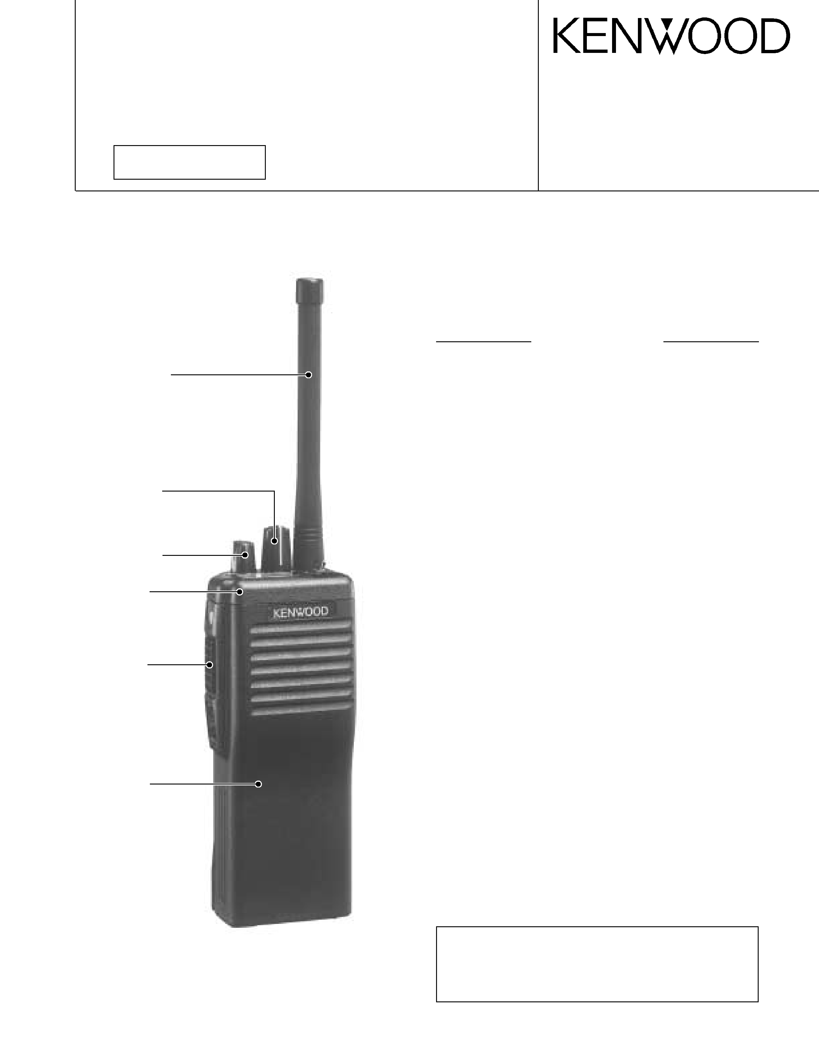
Photo is TK-290 K type.
Does not come with antenna.
Antenna is available as an option.
CONTENTS
GENERAL ................................................................. 2
SYSTEM SET-UP ..................................................... 2
OPERATING FEATURES ......................................... 3
REALIGNMENT ...................................................... 11
CIRCUIT DESCRIPTION ......................................... 17
SEMICONDUCTOR DATA ..................................... 25
DESCRIPTION OF COMPONENTS ....................... 26
PARTS LIST ............................................................ 28
EXPLODED VIEW .................................................. 36
PACKING ................................................................ 37
DISASSEMBLY FOR REPAIR ................................ 38
ADJUSTMENT ....................................................... 39
PC BOARD VIEWS
FINAL UNIT (X45-3592-71) ............................... 50
CONTROL UNIT (X53-3930-XX) ....................... 51
TX-RX UNIT (X57-5390-10) .............................. 55
SCHEMATIC DIAGRAM ........................................ 61
BLOCK DIAGRAM .................................................. 67
LEVEL DIAGRAM ................................................... 69
TERMINAL FUNCTION .......................................... 70
KNB-17A (Ni-Cd BATTERY) ................................... 71
KMC-25/26 (SPEAKER MICROPHONE) ................ 72
KSC-19 (CHARGER) ................................................ 73
KSC-20 (RAPID CHARGER) .................................... 73
KPG-36 (PROGRAMMING INTERFACE CABLE) ...... 73
KRA-14 (HELICAL ANTENNA) ............................... 73
SPECIFICATIONS ............................... BACK COVER
CAUTION
When using an external power connector,
please use with maximum final module protec-
tion of 10V
REVISED
Antenna
(KRA-14 : Option)
Cabinet assy
(A02-2139-63)
Knob assy (SEL)
(K29-5282-04)
Knob assy (VOL)
(K29-5283-04)
Panel assy
(A62-0537-53)
Knob assy
(Side key)
(K29-5441-04)
2
TK-290
GENERAL / SYSTEM SET-UP
INTRODUCTION
SCOPE OF THIS MANUAL
This manual is intended for use by experienced techni-
cians familiar with similar types of commercial grade com-
munications equipment. It contains all required service in-
formation for the equipment and is current as of the publica-
tion data. Changes which may occur after publication are
covered by either Service Bulletins or Manual Revisions.
These are issued as required.
ORDERING REPLACEMENT PARTS
When ordering replacement parts or equipment informa-
tion, the full part identification number should be included.
This applies to all parts : components, kits, or chassis. If the
part number is not known, include the chassis or kit number
of which it is a part, and a sufficient description of the re-
quired component for proper identification.
PERSONNEL SAFETY
The following precautions are recommended for person-
nel safety :
· DO NOT transmit until all RF connectors are verified se-
cure and any open connectors are properly terminated.
· SHUT OFF and DO NOT operate this equipment near
electrical blasting caps or in an explosive atmosphere.
· This equipment should be serviced by a qualified techni-
cian only.
SERVICE
This radio is designed for easy servicing. Refer to the
schematic diagrams, printed circuit board views, and align-
ment procedures contained within.
NOTE
WE CANNOT guarantee oscillator stability when using
channel element manufactured by other than KENWOOD or
its authorized agents.
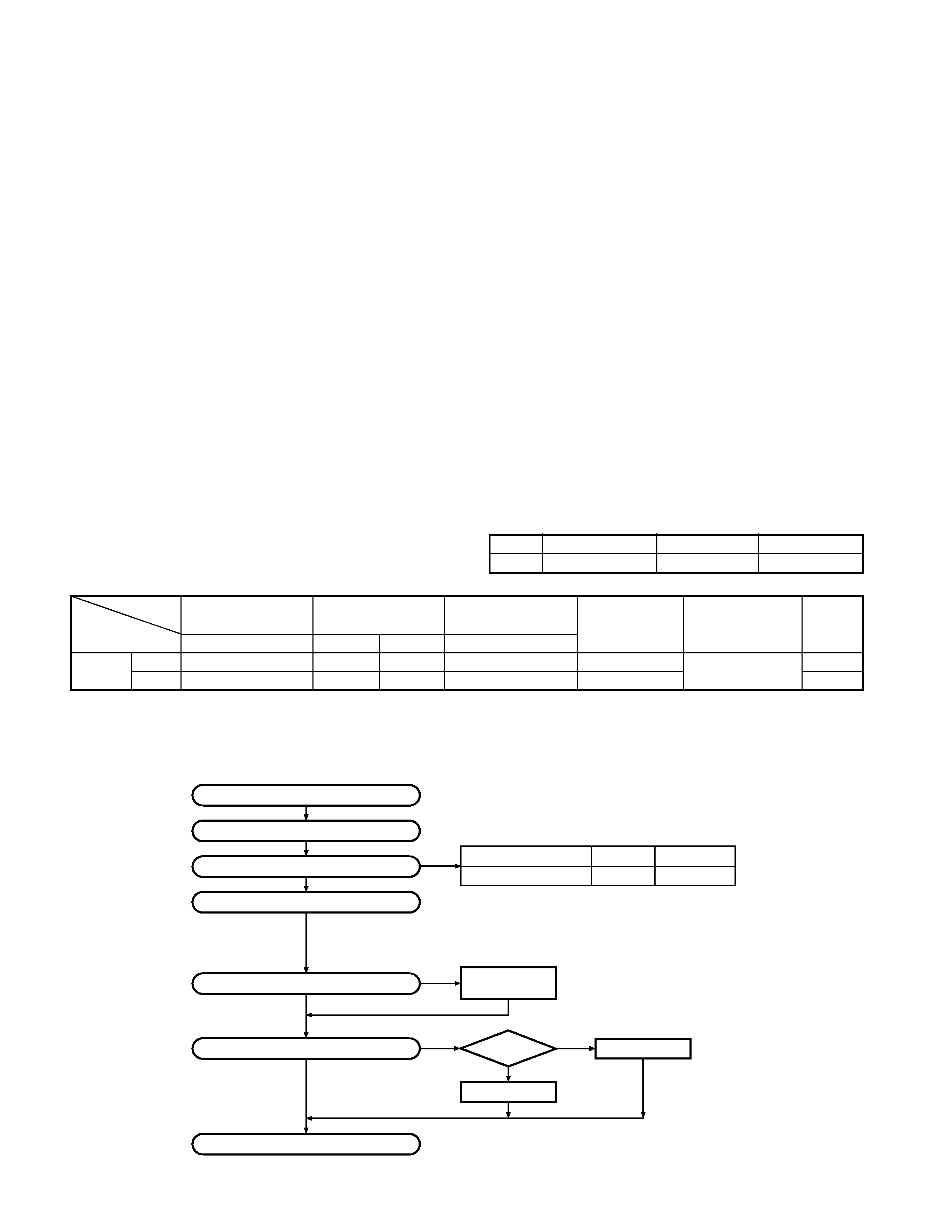
FCC COMPLIANCE AND TYPE NUMBERS
Model
Type acceptance number Frequency range
Compliance
TK-290
ALH21893110
136~174MHz
Parts 22,74,80,90
Unit
X57-539X-XX
X53-393X-XX
X45-359X-XX
DTMF
Model &
Frequency range
Remarks
keypad
destination
0-10
0-11
0-12
2-71
TK-290
K
136~174MHz
1st IF : 44.85MHz
K2
136~174MHz
LOC : 45.305MHz
Merchandise received
License and frequency allocated by FCC
Choose the type of transceiver
Transceiver programming
Are you using the optional antenna?
Delivery
Are you using the speaker microphone?
TX/RX 136~174
5W
TK-290 K,K2
Frequency range (MHz) RF power
Type
A personal computer (IBM PC or compatible), programming
interface (KPG-36), and programming software (KPG-38D)
are required for programming.
(The frequency, and signalling data are programmed for the
transceiver.)
YES
YES
YES
NO
NO
NO
KRA-14
Helical antenna
(Option)
With
antenna?
KMC-25
KMC-26
SYSTEM SET-UP
3
TK-290
OPERATING FEATURES
1. Getting Acquainted
1-1. Key Descriptions
TX/Busy/Battery low indicator
Lights red while transmitting. Lights green while receiv-
ing. Flashes red when the battery power is low while
transmitting; replace or recharge the battery.
Note : This indicator can be disabled by your dealer.
Power switch/Volume control
Turn clockwise to switch ON the transceiver. Turn coun-
terclockwise, until a click sounds, to switch OFF the
transceiver. Rotate to adjust the volume level.
Selector
Rotate this control to activate its programmable function
(Page 8).
Toggle switch
Switch the toggle position to activate its programmable
function (Page 8).
Top 1
Top 2
Orange
Side 1
Side 2
PTT (Push-To-Talk) switch
Press this switch, then speak into the microphone to call
a station.
Press these PF (programmable function)
keys to activate their programmable func-
tions (Page 8)
DTMF keypad (keypad models only)
Press the keys on the telephone keypad to send DTMF
tones.
Universal connector
Connect the external speaker/microphone (optional)
here. Otherwise, keep the supplied cover in place.
1-2. Display
Alphanumeric display
Displays the operating group or channel number, or the
group or channel name. When making a DTMF or 2 Tone
call, the display will alternate between CALL and the
channel. Also displays various menu functions.
7 Segment display
Displays the operating group or channel number. Also
displays tA (Talk Around), P1 (Priority1), P2 (Priority2), PP
(Priority1 and Priority2), or HC (Home Channel); depend-
ing on the function being used.
A (Add) indicator
Appears when a channel is added to the scanning se-
quence.
SCN (Scan) indicator
Appears when Scan mode is active.
MON (Monitor) indicator
Appears when the monitor function is active.
LO (Low) indicator
Appears when low power is selected.
OPT indicator
Appears when Operator Selectable Tone is enabled.
AUX (Auxiliary) indicator
Appears when Aux is ON. Appears and blinks when the
optional scrambler board is enabled.
Note : The alphanumeric and 7 segment displays can be
inverted if a PF key or the toggle switch is programmed
with Invert Display (Page 8).
AB
AB
SMA male type
antenna connector
Battery pack
release latch
Microphone
Display
Speaker

4
TK-290
2. Scan Operating
2-1. Scan Types
· Single Group Scan
You can scan all valid (ADD) channels in the displayed
group that can be selected with the group selector.
· Multiple Group Scan
You can scan all valid (ADD) channels in the all valid
(ADD) group.
2-2. Scan Start Condition
One or more non-priority channels must be added to all
channels that can be scanned. The transceiver must be in
normal receive mode (PTT off).
When you activate the key or the toggle switch (to right
position) programmed to the scan function, the scan starts.
The scan icon "SCN" lights and "SCAN" or revert channel
(programmable) is indicated on 7-digit alphanumeric display.
2-3. Scan Stop Condition
The scan stops temporarily if the following conditions are
satisfied.
1) A carrier is detected, then signalling matches on chan-
nels for which receive the signalling is set by the pro-
gramming software.
2) A carrier is detected on the channel for which receiving
signalling is not set by the programming software or
when the monitor (signalling cancel) function is activated.
2-4. Scan Channel Types
1) Priority channel 1 is the most important channel for the
scan, and always detects a signal during scan and when
the scan stops temporarily.
2) Priority channel 2 is the next important channel for the
scan, and always detects a signal during scan and when
the scan stops temporarily at a channel other than priority
channel 1.
3) Non-priority channels detects a signal during scan. For
the channels that can be selected with the group or chan-
nel selector when the scan does not occur, adds an indi-
cator "A" lights.
2-5. Priority Channel Setting
Priority channels 1 or 2 can be set as follows with the
programming software (KPG-38D).
1) Specify priority channels 1 or 2 as fixed priority channels.
2) Make selected channels, priority channels.
3) Operator delectable
Specify the initial channel before the operator changes it.
2-6. Scan Type According to the Priority Channel
1) When no priority channels are set : Only the non-priority
channels are scanned.
If a non-priority channel stops temporarily, it stops until
there is no signal on the channel.
OPERATING FEATURES
2) When one priority channel is set : Either priority channel
1 or 2 is scanned.
If a non-priority channel stops temporarily, a priority chan-
nel signal is detected at certain intervals.
If a priority channel stops temporarily, it stops until there
is no signal on the priority channel.
3) When two priority channels are set : The non-priority
channel, priority channels 1 and 2 are scanned.
If a non-priority channel stops temporarily, priority chan-
nel 1 and 2 signals are detected at certain intervals.
If priority channel 2 stops temporarily, the priority chan-
nel 1 signal is detected at certain intervals.
If priority channel 1 stops temporarily, it stops until there
is no signal on priority channel 1.
2-7. Revert Channel
The revert channel is used to transmit during scanning
and set by the programming software (KPG-38D).
1) Priority 1
The transceiver reverts to the priority channel 1.
2) Priority 1 with talkback
The transceiver reverts to the priority channel 1.
If you press PTT during a resume timer (dropout delay
time, TX dwell time) or calling, you can transmit on cur-
rent channel to answer to the call however revert channel
is set to priority channel 1.
After resume time, scan re-starts and transmission chan-
nel is return to priority channel 1.
3) Priority 2
The transceiver reverts to the priority channel 2.
4) Priority 2 with talkback
The transceiver reverts to the priority channel 2.
If you press PTT during resume timer (dropout delay
time, TX dwell time) or calling, you can transmit on cur-
rent channel to answer to the call however revert channel
is set to priority channel 2.
After resume time, scan re-starts and transmission chan-
nel is return to priority channel 2.
5) Selected channel
The transceiver reverts to the channel before scanning or
the channel that you changed during scan.
6) Last called channel
The transceiver reverts to the last called channel during
the scan.
7) Last used channel
The transceiver reverts to the last used (transmitted)
channel during scan. "Last used" revert channel in-
cludes talkback function.
8) Selected with talkback
The transceiver reverts to the channel before scanning or
the channel that you changed during scan.
2-8. Scan End
When you reactivate the key or the toggle switch (to left
position) programmed to the scan function during scan
mode, the scan ends.
The scan icon "SCN" and "SCAN" or revert channel (pro-
grammable) display goes off.

5
TK-290
2-9. Temporarily Delete/Add
It is possible to delete or add channel temporarily during
scan. When scan stops on unnecessary channel for ex-
ample by interference of the other party, activate the delete/
add function (for example press the key), then that channel
is deleted temporarily and scan re-start immediately.
When you would like to add the deleted channel tempo-
rarily to scan sequence, select the desired (deleted) channel
during scan, activate the delete/add function (for example
press the key) before scan re-start.
That channel is added temporarily to scan sequence. The
temporary deleted or added channels are returns to pre-set
delete/add, when the transceiver exits from scan mode.
3. Optional Features
You can use these features using the programming soft-
ware (KPG-38D).
3-1. Alphanumeric Display (Group/Channel Name)
The programming software (KPG-38D) enables you to set
the alphanumeric display for group/channel name. The total
text size of group and channel name are 7-digits.
For example, If you set 2-digits for group name, then you
can use 5-digits for channel name. The characters can be
used as shown in Figure 1.
3-2. Beep Tones
The beep tones (power on tone, control tone, warning
tone, alert tone) are individually programmable to the fixed
level 0 to 31 or follow the mechanical volume position.
3-3. Minimum Volume
The minimum volume is programmable (0 to 31). The
transceiver remains the minimum volume level however the
mechanical volume position is set to zero.
AB C D E
F G H
I
J K
L M N OPQ R
ST U V W X Y Z
1
2
345678
9
0-
All on
Fig. 1
3-4. Squelch Threshold Level
Squelch threshold level value.
0 (Most loose)~15 (Most tight)
3-5. BCL (Busy Channel Lockout) Override
You can transmit in spite of Busy Channel Lockout situa-
tion. For example : To make an emergency voice call.
To transmit under busy channel lockout situation, press
PTT once more within approx. 500ms after the PTT release.
3-6. Selective Call Alert LED
You can select whether or not the LED on the transceiver
flashes in an orange color when Selective call was occurred.
3-7. Battery Warning
This transceiver has battery warning feature. If the low
voltage is detected during transmission, the transceiver
warns it by flashing red "LED".
Then more low voltage is detected during transmission,
the transceiver stops transmission and warns it by flashing
red "LED" and beep.
Please notice "standard" for the battery exchange,
charging time by flashing red LED and beep.
3-8. Busy LED
You can program the enable or disable the busy "LED"
function when a carrier is detected. "Disable" saves battery
life.
3-9. TX LED
You can program the enable or disable the transmission
"LED" function.
3-10. 2-Digit 7-Segment Display
You can use 2-digit 7-segment the display to display the
channel number or group number. It is useful when the
main (7-digit 13-segment) display indicates group or channel
name.
3-11. Invert Display
Main (7-digit 13-segment) display and sub (2-digit 7-seg-
ment) display can be programmed to invert display.
It is easy to read the display when the operator sus-
pended the transceiver on a waste belt. The operator also
can change the display between normal and invert using
key. Refer the invert display function of key function.
3-12. Clear to Transpond
The transceiver waits the transpond of 2-Tone/DTMF if
channel is busy until channel open. This feature prevents
the interference to other party.
3-13. External Speaker
It can be selected if the receive sound is made by SP-Mic
SP or the main body SP at a SP-Mic mount.
3-14. Noise Cancelling MIC
Enable or disable the noise cancelling function of the in-
ternal microphone. It is not valid for the external SP/MIC.
OPERATING FEATURES