VHF FM TRANSCEIVER /
VHF
TK-2207
© 2004-2 PRINTED IN JAPAN
B51-8679-00 (S) 663
SERVICE MANUAL /
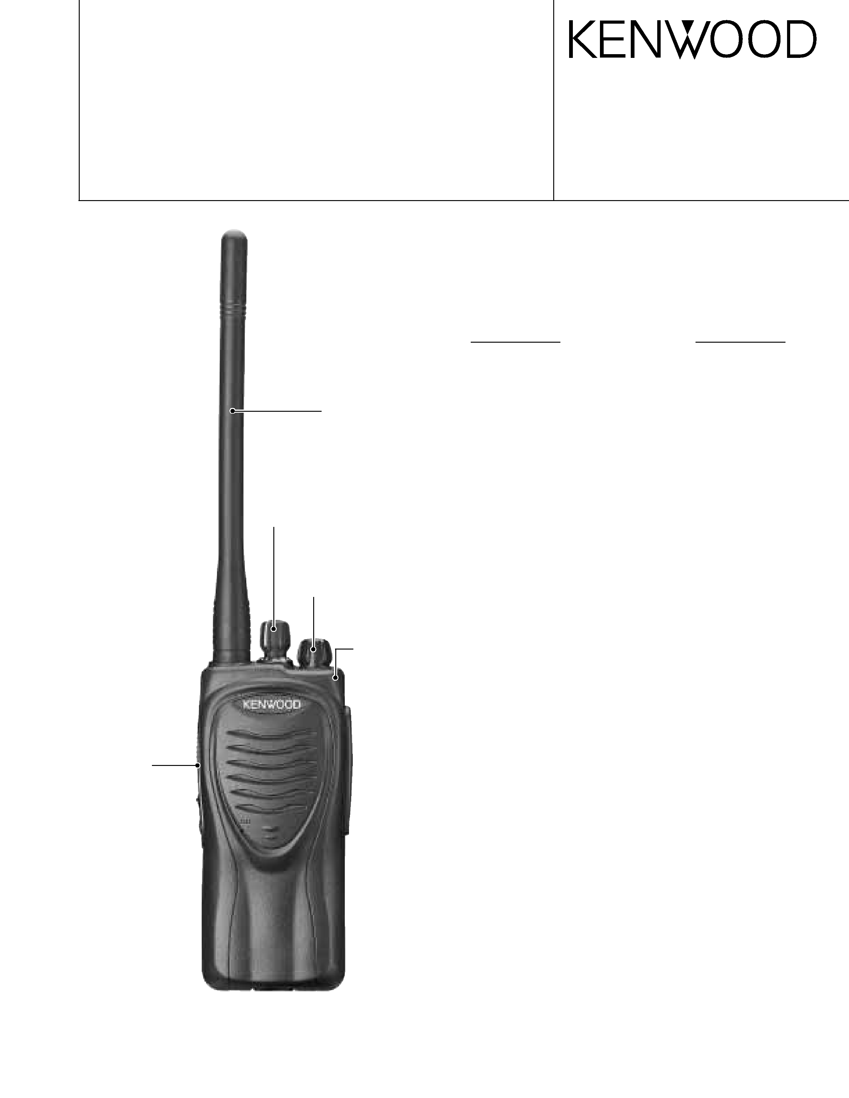
Does not come with antenna. Antenna is available as an option.
GENERAL ............................................................. 2
SYSTEM SET-UP ................................................. 3
REALIGNMENT .................................................... 4
DISASSEMBLY FOR REPAIR .............................. 7
CIRCUIT DESCRIPTION ..................................... 12
TERMINAL FUNCTION ...................................... 20
SEMICONDUCTOR DATA ................................. 20
COMPONENTS DESCRIPTION ......................... 22
PARTS LIST ........................................................ 24
EXPLODED VIEW ............................................... 30
PACKING ............................................................ 31
ADJUSTMENT ................................................... 32
PC BOARD
TX-RX UNIT (X57-6870-20) .......................... 42
SCHEMATIC DIAGRAM ..................................... 46
BLOCK DIAGRAM .............................................. 50
LEVEL DIAGRAM ............................................... 52
KSC-31 / KNB-29N ............................................. 53
KNB-30A / KBH-10 ............................................. 54
SPECIFICATIONS ............................................... 55
CONTENTS
Knob (CH-SELECTOR)
()
(K29-9318-03)
Knob (VOLUME)
()
(K29-9309-03)
Cabinet assy
(A02-3851-23)
Antenna
(KRA-26: Option /
)
Knob (PTT)
(PTT)
(K29-9308-03)

TK-2207
2
INTRODUCTION
SCOPE OF THIS MANUAL
This manual is intended for use by experienced technicians
familiar with similar types of commercial grade
communications equipment. It contains all required service
information for the equipment and is current as of the
publication date. Changes which may occur after publication
are covered by either Service Bulletins or Manual Revisions.
These are issued as required.
ORDERING REPLACEMENT PARTS
When ordering replacement parts or equipment information,
the full part identification number should be included. This
applies to all parts : components, kits, or chassis. If the part
number is not known, include the chassis or kit number of
which it is a part, and a sufficient description of the required
component for proper identification.
PERSONNEL SAFETY
The following precautions are recommended for personnel
safety:
DO NOT transmit until all RF connectors are verified secure
and any open connectors are properly terminated.
SHUT OFF and DO NOT operate this equipment near
electrical blasting caps or in an explosive atmosphere.
This equipment should be serviced by a qualified technician only.
............................................................................................... 2
...................................................................................... 3
...................................................................................... 4
...................................................................................... 7
.................................................................................... 12
.................................................................................... 20
................................................................................ 20
.................................................................................... 22
........................................................................................ 24
................................................................................ 30
............................................................................................. 31
............................................................................................. 32
PC
TXRX (X57-6870-20) ............................................ 42
........................................................................................ 46
........................................................................................ 50
........................................................................................ 52
KSC-31 / KNB-29N .................................................................... 53
KNB-30A / KBH-10 ................................................................... 54
.........................................................................................
GENERAL /
TK-2207
3
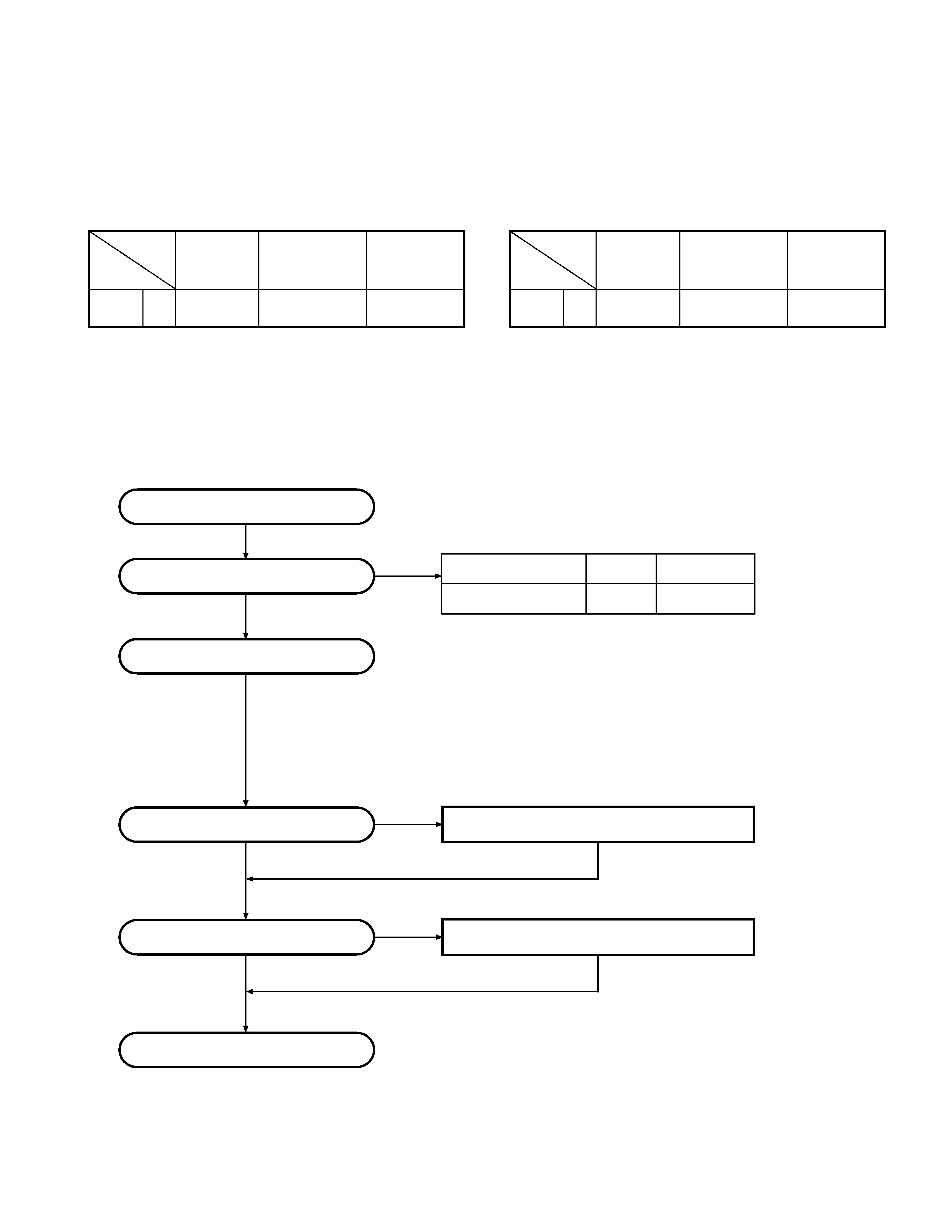
SYSTEM SET-UP /
SYSTEM SET-UP /
Merchandise received
Choose the type of transceiver
Transceiver programming
Are you using the optional antenna?
KRA-22 or KRA-26 optional antenna
YES /
NO /
TX/RX
5.0W
TK-2207(M)
Frequency range (MHz)
RF power
Type
136~174
A personal computer (IBM PC or compatible), programming
interface (KPG-22), and programming software (KPG-87D)
are required for programming.
(The frequency, TX power HI/LOW, and signalling data are programmed
for the transceiver.)
(IBM)(KPG-22)
(KPG-87D)
(TX/ )
?
KRA-22 KRA-26
Delivery
Are you using the speaker microphone?
KMC-17 or KMC-21 Speaker microphone
YES /
NO /
( Option /
)
?
KMC-17KMC-21
MHz
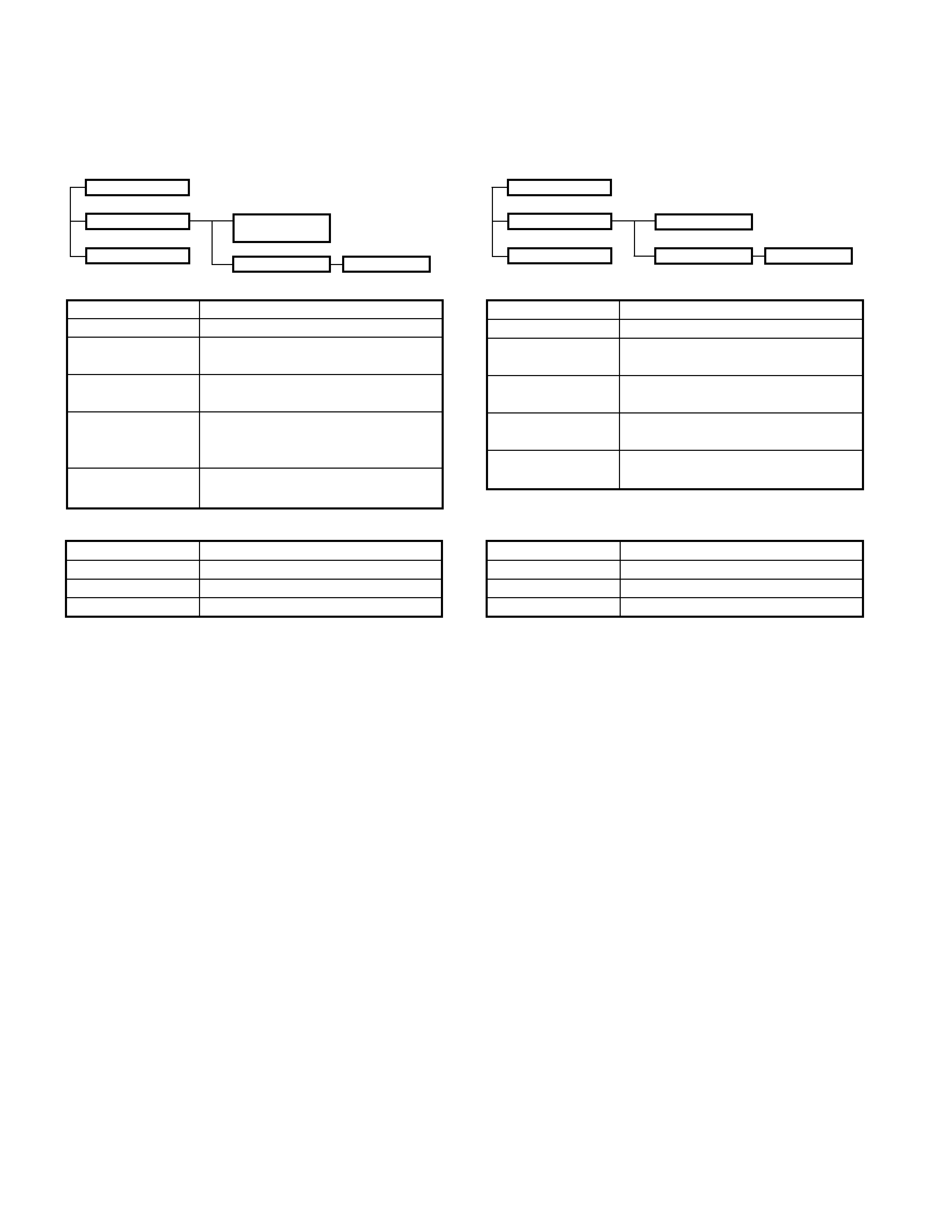
GENERAL /
Unit
Model
TX-RX Unit
Frequency range
Remarks
& destination
TK-2207
M
X57-6870-20
136~174MHz
IF1 : 38.85MHz
LOC : 38.4MHz
TX-RX
TK-2207
M
X57-6870-20
136~174MHz
IF1 : 38.85MHz
LOC : 38.4MHz
SERVICE
This radio is designed for easy servicing. Refer to the
schematic diagrams, printed circuit board views, and alignment
procedures contained within.
TK-2207
4
REALIGNMENT /
3.PC Mode
3-1. Preface
The TK-2207 transceiver is programmed using a personal
computer, a programming interface (KPG-22) and programming
software (KPG-87D).
The programming software can be used with an IBM PC
or compatible. Figure 1 shows the setup of an IBM PC for
programming.
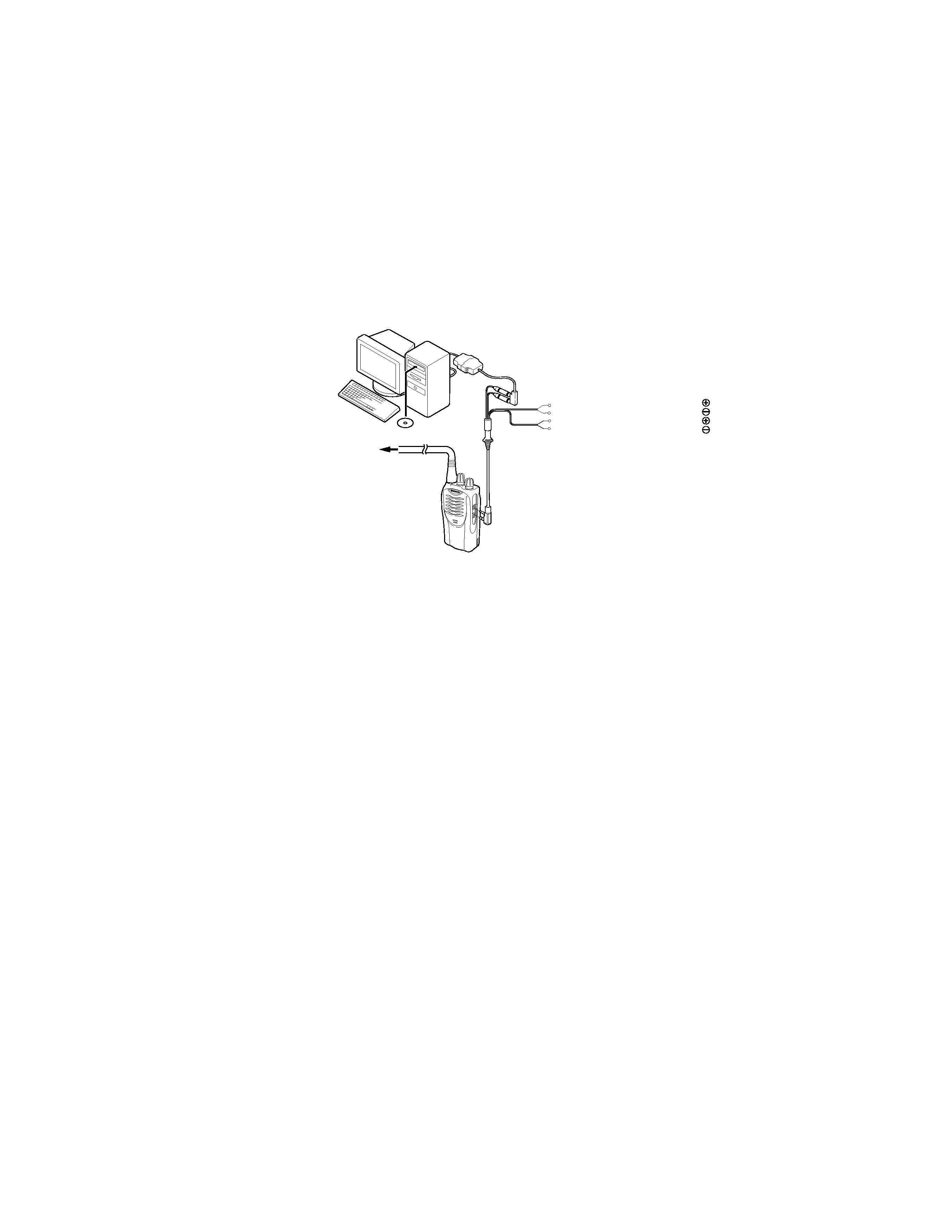
3-2. Connection procedure
1. Connect the TK-2207 to the personal computer with the
interface cable.
2. When the POWER is switched on, user mode can be
entered immediately. When the PC sends a command,
the radio enters PC mode.
When data is transmitting from the transceiver, the red
LED lights.
When data is received by the transceiver, the green LED lights.
Notes:
· The data stored in the personal computer must match the
model type when it is written into the EEPROM.
· Change the TK-2207 to PC mode, then attach the interface
cable.
3-3. KPG-22 description
(PC programming interface cable: Option)
The KPG-22 is required to interface the TK-2207 with the
computer. It has a circuit in its D-subconnector (25-pin) case
that converts the RS-232C logic level to the TTL level.
3.
3-1
TK-2207 KPG-22
KPG-87D
IBM 1 IBM
3-2
1. TK-2207
2. PC
PC
·
EEPROM ,
·
TK-2207
3-3 KPG-22 (PC )
TK-2207 KPG-22
D 25 RS-232C TTL
KPG-22 TK-2207
(IBM )
KPG- 87D
1 .
1. Modes
REALIGNMENT
2. How to Enter Each Mode
Mode
Operation
User mode
Power ON
PC mode
Received commands from PC
Clone mode
[PTT]+[Side2]+Power ON (Two seconds)
2.
[PTT]+[ 2]+ 2
Mode
Function
User mode
For normal use.
PC mode
Used for communication between the
radio and PC (IBM compatible).
Data programming
Used to read and write frequency data
mode
and other features to and from the radio.
PC test mode
Used to check the radio using the PC.
This feature is included in the KPG-
87D.
Clone mode
Used to transfer programming data
from one radio to another.
User mode
PC mode
PC test mode
Data programming
mode
PC tuning mode
Clone mode
TK-2207
5
The KPG-22 connects the side panel connector of the TK-
2207 to the computer's RS-232C serial port.
3-4. Programming software description
KPG-87D is the programming software for TK-2207
supplied on a CD-ROM. This software runs under Windows
98, ME, Windows 2000 or XP on an IBM-PC or compatible
machine.
The data can be input to or read from TK-2207 and edited
on the screen. The programmed or edited data can be printed
out. It is also possible to tune the transceiver.
RS-232C
3-4
KPG-87D TK-2207
IBM-PC Windows 98,ME,Windows 2000 XP
TK-2207
REALIGNMENT /
Fig. 1 /
Tuning cable /
(E30-3216-05)
RF Power meter or SSG
/ RF SSG
/
1.5D-XV
1.5D-XV
}
}
SP
MIC
KPG-22
KPG-87D
IBM-PC /
IBM
Gray
Gray/Black
1.5D-XV Lead wire
1.5D-XV Shield wire
4. Clone Mode
4-1. Outline
"Clone Mode" copies the transceiver data to another
transceiver.
The dealer can copy the transceiver data to another
transceiver even without the use of a personal computer.
4-2. Example
The transceiver can copy the programming data to one or
more transceivers via RF communication.
The clone master and clone slave/s must be in Clone mode.
4-3. Operation
1. To switch the clone slave/s to Clone mode, press and hold
the [PTT] and [side2] keys while turning the transceiver
power ON.
2. Wait for 2 seconds. The LED will light orange and the
transceiver will announce "Clone".
3. Select a channel table number using Side1(increment
channel table) and Side2(decrement channnel table) keys.
4. To switch the clone master to Clone mode, press and hold
the [PTT] and [side2] keys while turning the transceiver
power ON.
5. Wait for 2 seconds. The LED will light orange and the
transceiver will announce "Clone".
6. Select the same channel table number as the clone slave/s.
7. Press [PTT] on the clone master to begin data transmission.
When the clone slave starts to receive data, the LED will
light green.
When the clone master finishes sending data, a
"confirmation" tone will sound.
If data transmission fails while cloning, an "error" tone will
sound from the Slave unit.
4.
4-1
""
4-2 :
RF
4-3
1.
[PTT] [ 2]
2. 2LED""
3. 1 () 2 ()
4.
[PTT] [ 2]
5. 2LED""
6.
7. [PTT]
LED
""
""
8.
9. " " " "
( =OFF, =OFF)