© 2000-05 PRINTED IN JAPAN
B51-8536-00(S) 200
VHF FM TRANSCEIVER
TK-2107
SERVICE MANUAL
GENERAL .................................................................. 2
REALIGNMENT ......................................................... 2
DISASSEMBLY FOR REPAIR ................................... 4
CIRCUIT DESCRIPTION ........................................... 5
SEMICONDUCTOR DATA ......................................... 9
DESCRIPTION OF COMPONENTS ........................ 10
PARTS LIST ............................................................. 11
EXPLODED VIEW ................................................... 17
PACKING ................................................................. 18
ADJUSTMENT ......................................................... 19
PC BOARD VIEWS
TX-RX UNIT (X57-6020-21) ................................ 23
SCHEMATIC DIAGRAM .......................................... 27
BLOCK DIAGRAM .................................................. 31
LEVEL DIAGRAM ................................................... 33
KNB-15A (Ni-Cd BATTERY) ................................... 34
SPECIFICATIONS ................................ BACK COVER
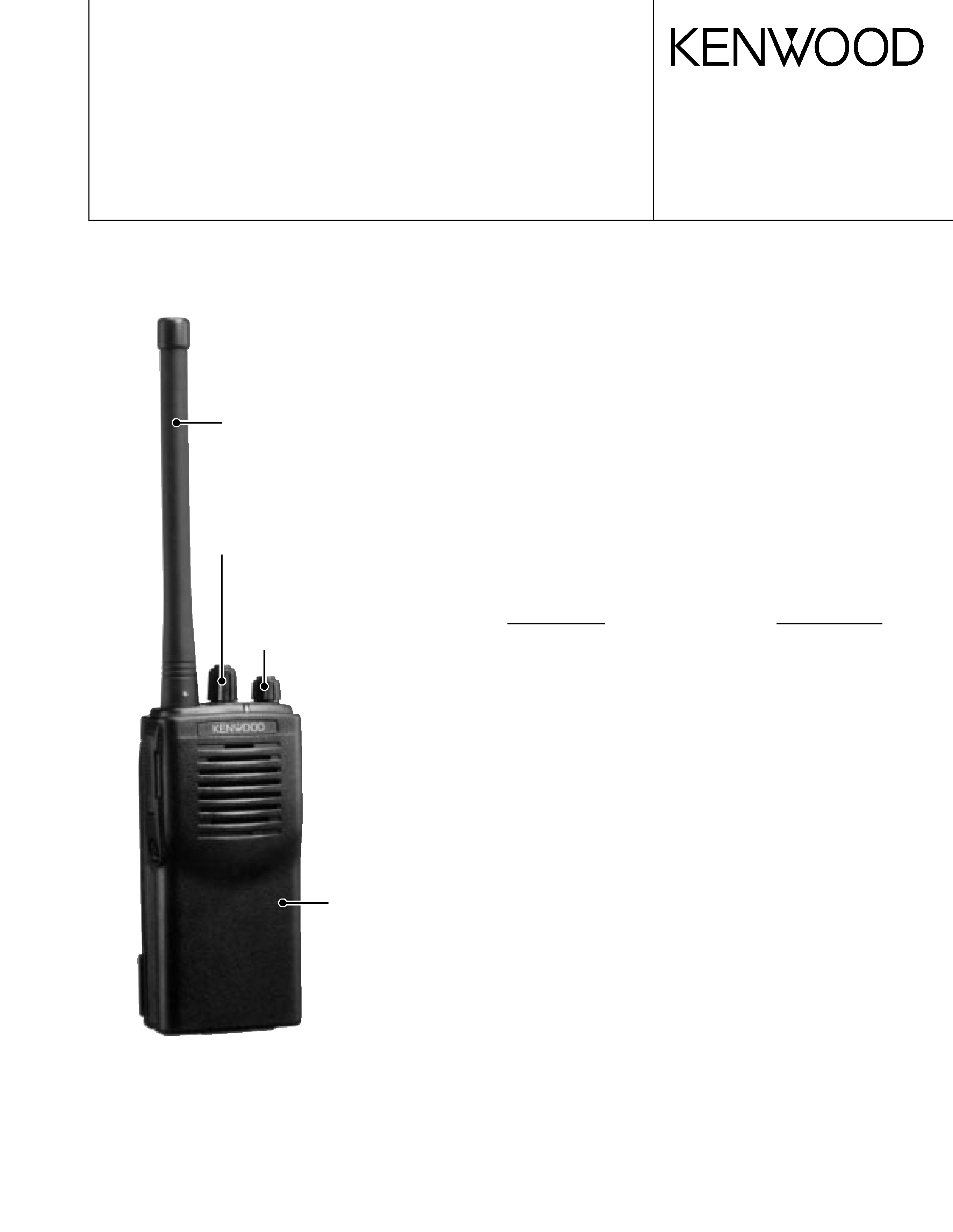
Antenna
(T90-0733-05):M3
Cabinet assy
(A02-2448-13)
Knob(VOLUME)
(K29-5255-03)
TK-2107 (16 channels)
CONTENTS
Knob
(CHANNEL SELECTOR)
(K29-5278-03)
2
TK-2107
TK-260
:K, K2
MODE
FUNCTION
User Mode
Use this mode for normal operation.
PC Mode
Use this mode, to make various
settings by means of the FPU through
the RS-232C port.
Manufacture Mode Use this mode, to realign the various
settings through the RS-232C port
during manufacture work.
2 How to enter each mode
MODE
PROCEDURE
User Mode
Power ON
PC Mode
Connect to the IBM PC compatible
machine and controled by the FPU.
INTRODUCTION
SCOPE OF THIS MANUAL
This manual is intended for use by experienced technicians
familiar with similar types of commercial grade
communications equipment. It contains all required service
information for the equipment and is current as of the
publication data. Changes which may occur after publication
are covered by either Service Bulletins or Manual Revisions.
These are issued as required.
ORDERING REPLACEMENT PARTS
When ordering replacement parts or equipment
information, the full part identification number should be
included. This applies to all parts : components, kits, or
chassis. If the part number is not known, include the chassis or
kit number of which it is a part, and a sufficient description of
the required component for proper identification.
GENERAL/REALIGNMENT
3 Getting acquainted
PC Mode
User Mode
Manufacture Mode
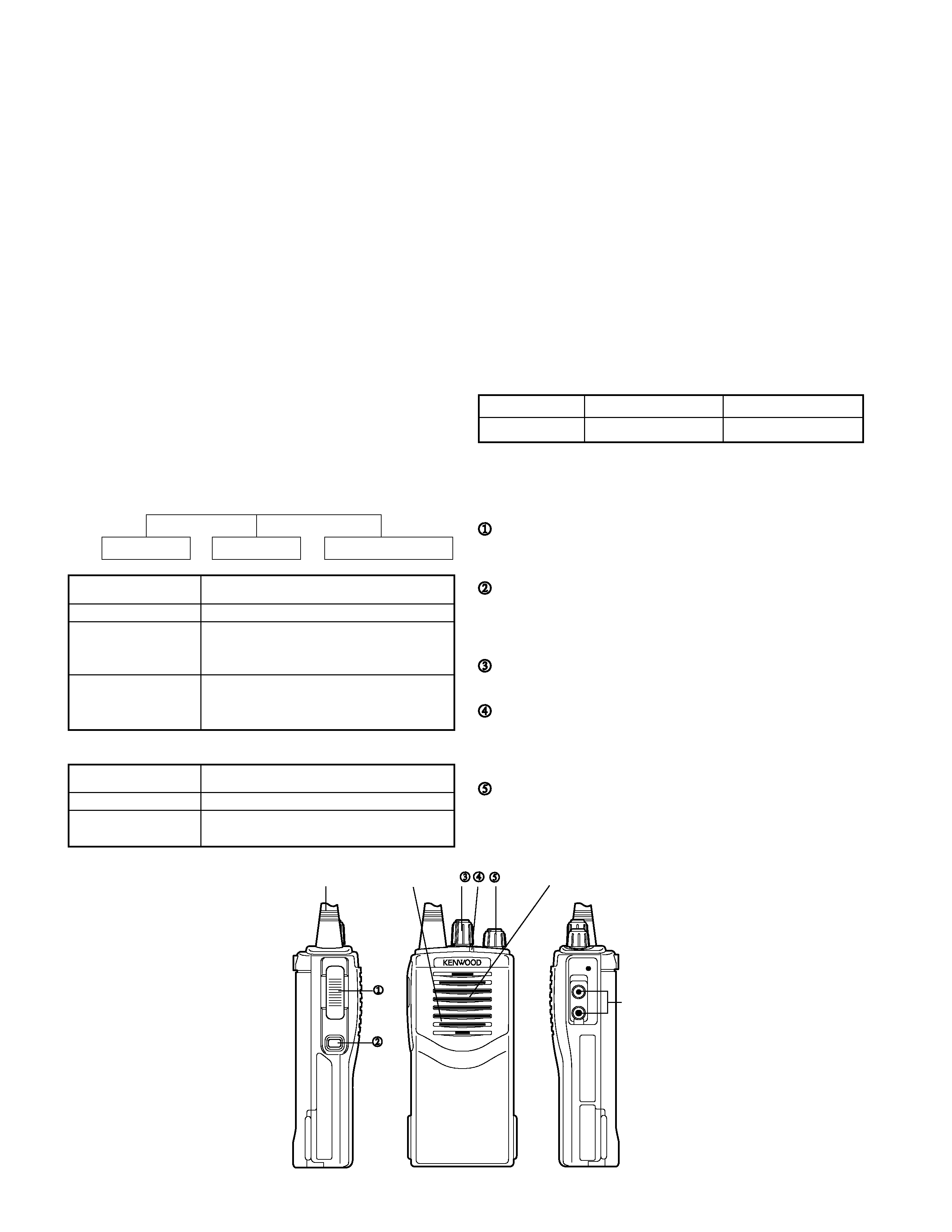
Speaker
Antenna
Speaker/
microphone
jacks
PTT (Push-To-Talk) switch
Press this switch, then speak into the microphone to
call a station. Release the switch to receive.
Monitor key
Press and hold to monitor how busy the current
channel is and to monitor signals being received that
do not contain the matched QT/DQT code.
Channel selector
Rotate to select channels 1 ~ 16.
LED indicator
Lights red while transmitting, green while receiving a
signal. Flashes red when the battery voltage is low
while transmitting.
Power switch/ Volume control
Turn clockwise to switch the transceiver ON. Turn
counterclockwise until a click sounds, to switch the
transceiver OFF. Rotate to adjust the volume level.
Microphone
Destnation
Number of CH
RF power output
M3
16
5W
PERSONAL SAFETY
The following precautions are recommended for personal
safety :
· DO NOT transmit until all RF connectors are verified secure
and any open connectors are properly terminated.
· SHUT OFF and DO NOT operate this equipment near
electrical blasting caps or in an explosive atmosphere.
· This equipment should be serviced by a qualified
technician only.
SERVICE
This radio is designed for easy servicing. Refer to the
schematic diagrams, printed circuit board views, and
alignment procedures contained within.
REALIGNMENT
1 Modes
3
TK-2107
TK-260
:K, K2
REALIGNMENT
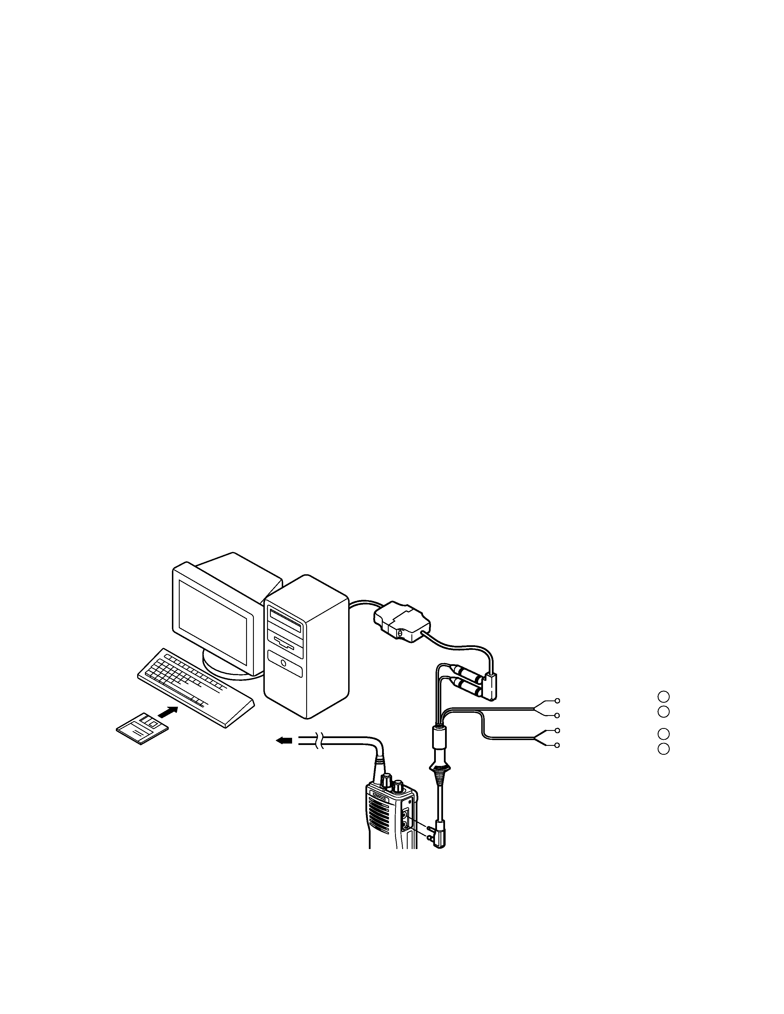
PC MODE
Preface
The transceiver is programmed by using a personal
computer, programming interface (KPG-22) and programming
software (KPG-55D).
The programming software can be used with an IBM PC or
compatible. Figure 1 shows the setup of an IBM PC for
programming.
Connenction procedure
1. Connect the TK-2107 to the personal computer with the
interface cable.
2. When data is transmitting from the transceiver the red LED
lights.
When data is receiving by the transceiver the green LED
lights.
Notes:
· The data stored in the personal computer must match the
Model Name when it is written into the EEPROM.
· Do not press the [PTT] key during data transmission or
reception.
Fig. 1
IBM-PC
KPG-55D
Gray
SP
MIC
Gray/Black
1.5D-XV Lead wire
1.5D-XV Shield wire
Tuning cable
(E30-3216-05)
KPG-22
RF Power meter
or SSG
-
+
-
+
}
}
· KPG-22 description
(PC programming interface cable: Option)
The KPG-22 is required to interface the TK-2107 with the
computer. It has a circuit in its D-subconnector (25-pin) case
that converts the RS-232C Iogic level to the TTL Ievel. The
KPG-22 connects the side panel jacks of the TK-2107 to the
computer's RS-232C serial port.
· Programming software description
The KPG-55D Programming Disk is supplied in 3-1/2" the disk
format. The Software on this disk allows a user to program
TK-2107 radios via a Programming interface cable (KPG-22).
· Programming with IBM PC
If data is transferred to the transceiver from an IBM PC with
the KPG-55D, the destination data (basic radio information)
for each set can be modified. Normally, it is not necessary to
modify the destination data because their values are
determined automatically when the frequency range
(frequency type) is set.
The values should be modified only if necessary.
Data can be programmed into the EEPROM in RS-232C
format via the SP MIC plug.
In this mode the PTT Iine operates as TXD and RXD data
lines respectively.
M3 type has wide mode only.
All narrow data should be not available, even thouth data would
be modified in test mode.
4
TK-2107
TK-260
:K, K2
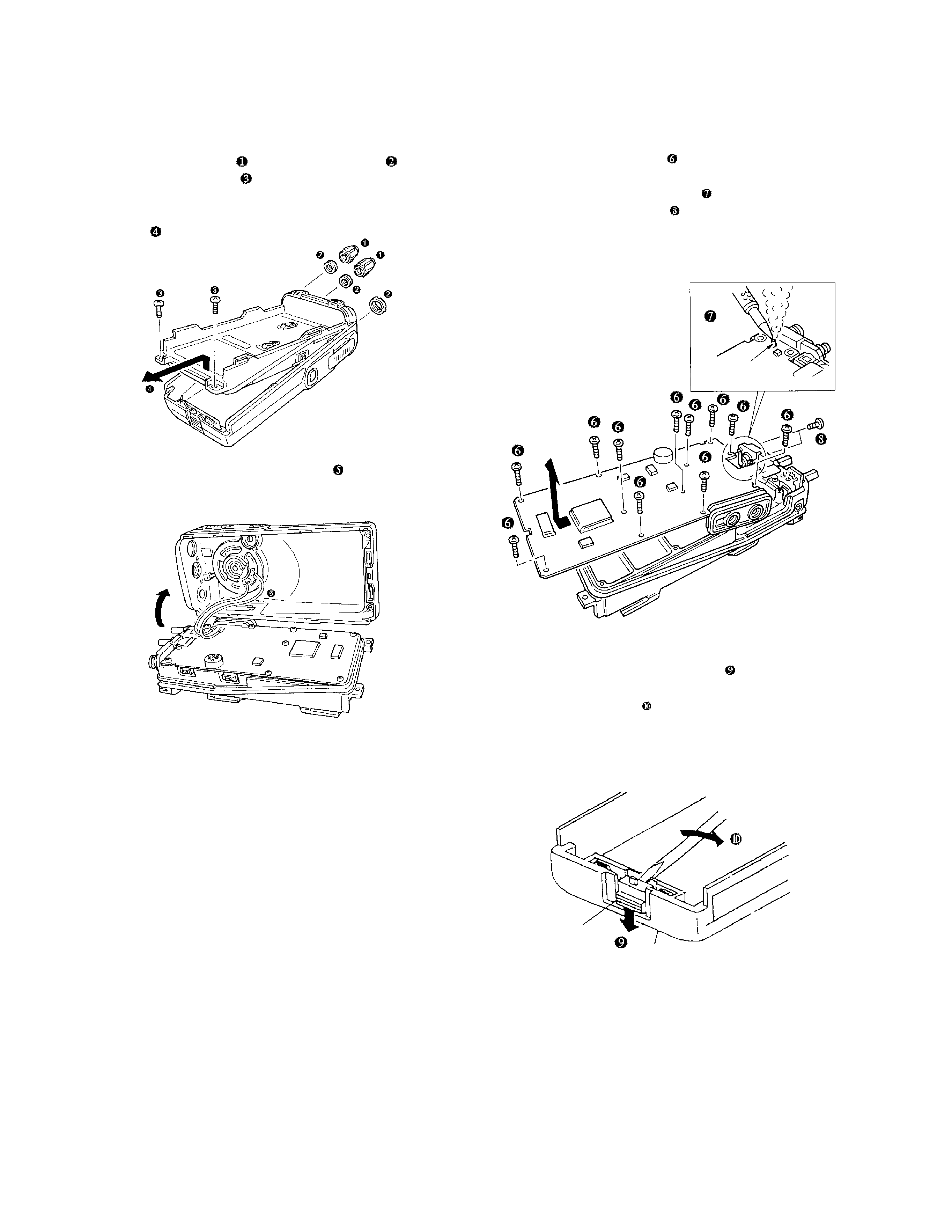
DISASSEMBLY FOR REPAIR
Separating the case assembly from the chassis
1. Remove the two knobs
and three round nuts
.
2. Remove the two screws
.
3. Expand the right and left sides of the bottom of the case
assembly, Iift the chassis, and remove it from the case
assembly
.
4. Taking care not to cut the speaker lead
, open the chassis
and case assembly.
Separating the chassis from the unit
1. Remove the eleven screws
.
2. Remove the solder from the antenna terminal using a
soldering iron then lift the unit off
.
3. Remove the two screws
and remove the antenna
connector.
Note : When reassembling the unit in the chassis, be sure to
solder the antenna terminal.
Removing the lever
1. Raise the lever on the lower case
, insert a small flat
screwdriver into the space between the case and lever,
open the case carefully
and lift the lever off.
Note : Do not force to separate the case from the lever.
Lever knob
Cace assembly
Antenna terminal
5
TK-2107
TK-260
:K, K2
1. Frequency configuration
The receiver utilizes double conversion. The first IF is
38.85MHz and the second IF is 450kHz. The first local
oscillator signal is supplied from the PLL circuit.
CIRCUIT DESCRIPTION
ANT
ANT SW
RF
AMP
MCF
CF
IF SYSTEM
AF
AMP
RX
TX
PA
AMP
TX
AMP
PLL
VCO
MIC
AMP
TCXO
X3
multiply
38.85MHz
450kHz
38.4MHz
12.8MHz
SP
MIC
Fig. 1 Frequency configuration
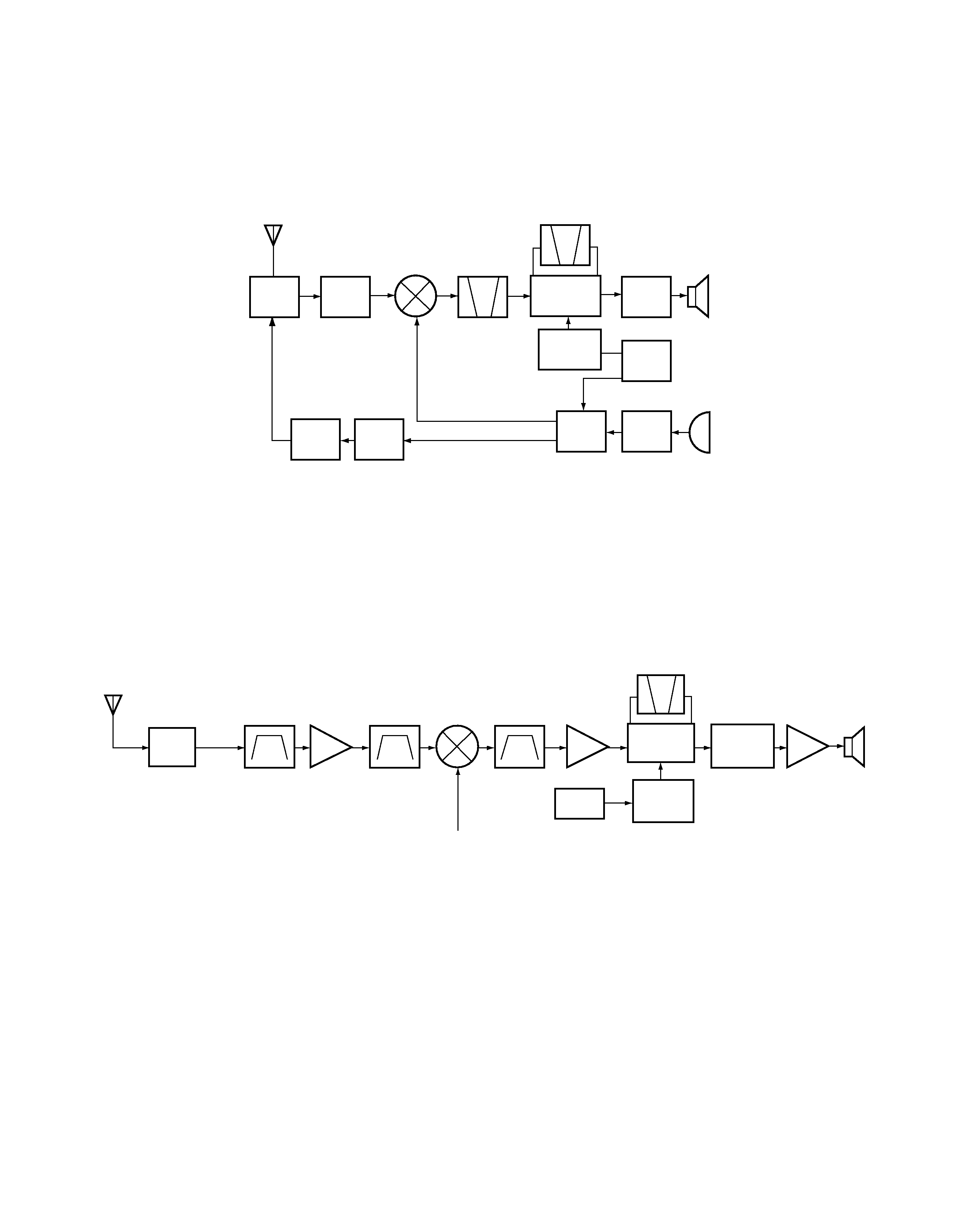
ANT
D102, D103
BPF
RF AMP
Q203
BPF
MIXER
Q202
MCF
XF200
IF AMP
Q201
CF200
IF, MIX, DET
IC200
AF AMP
LPF, HPF
IC300
AF PA AMP
IC302
SP
X3
multiply
Q1
TCXO
1st Local OSC
(PLL)
ANT SW
Fig. 2 Receiver section configuration
The PLL circuit in the transmitter generates the necessary
frequencies. Fig. 1 shows the frequencies.
2. Receiver
The receiver is double conversion superheterodyne,
designed to operate in the frequency range of 216 to 223MHz
(M3 type).
The frequency configuration is shown in Fig. 1.
1) Front - end RF amplifier
An incoming signal from the antenna is applied to an RF
amplifier (Q203) after passing through a transmit/receive
switch circuit (D102 and D103 are off) and a band pass filter
(L208, L209 and L210). After the signal is amplified (Q203),
the signal is filtered through a band pass filter (L203 and L214)
to eliminate unwanted signals before it is passed to the first
mixer. (See Fig. 2)
2) First Mixer
The signal from the RF amplifier is heterodyned with the
first local oscillator signal from the PLL frequency synthesizer
circuit at the first mixer (Q202) to create a 38.85MHz first
intermediate frequency (1st IF) signal. The first IF signal is
then fed through two monolithic crystal filters (MCFs : XF200)
to further remove spurious signals.
3) IF amplifier
The first IF signal is amplified by Q201, and then enters
IC200 (FM processing IC). The signal is heterodyned again
with a second local oscillator signal within IC200 to create a
450kHz second IF signal. The second IF signal is then fed
through a 450kHz ceramic filter (CF200) to further eliminate
unwanted signals before it is amplified and FM detected in
IC200.
4) AF amplifier
The recovered AF signal obtained from IC200 is amplified
by IC300 (1/4), filtered by the IC300 low-pass filter (2/4) and
IC300 high-pass filter (3/4) and (4/4), and de-emphasized by
R303 and C306. The processed AF signal passes through an
AF volume control and is amplified to a sufficient level to drive
a loud speaker by an AF power amplifier (IC302).