Type ...................... Subwoofer system with built-in amplifier
[Amplifier]
Dynamic Power ................................................. 100 W (6
)
(For U.S.A. and Canada)
Rated Output Power (FTC)
75 W RMS, at 6
100 Hz, with no more than 0.7 % T.H.D.
Input Sensitivity & Input Impedance ........ 300 mV (37 k
)
Rated Power Consumption ........................................ 70 W
Frequency Responce................................... 35 Hz ~ 200 Hz
(For other countries)
Rated Output Power ....................... 75 W RMS (100 Hz,6
)
Input Sensitivity & Input Impedance ........ 300 mV (37 k
)
Rated Power Consumption ........................................ 70 W
Frequency Responce................................... 35 Hz ~ 200 Hz
Notes:
1. Kenwood follows a policy of continuous advancements in development. For this reason, specifications may be
changed without notice.
2. Full performance may not be exhibited in extremely cold locations (below 0 deg . C).
[Speaker]
Enclosure ........................ Bass-Reflex, Floor Standing Type
Speaker Units ............................160 mm (6-1/2") Cone type
Nominal Impedance ....................................................... 6
Dimensions
Width ................................................... : 210 mm (8-1/4")
Height ................................................ : 400 mm (15-3/4")
Depth ................................................. : 350 mm (13-3/4")
Net W eight .................................................... 9.2 kg (20.3 lb)
Supplied accessories
Pin-plug cord .................................................................. 1
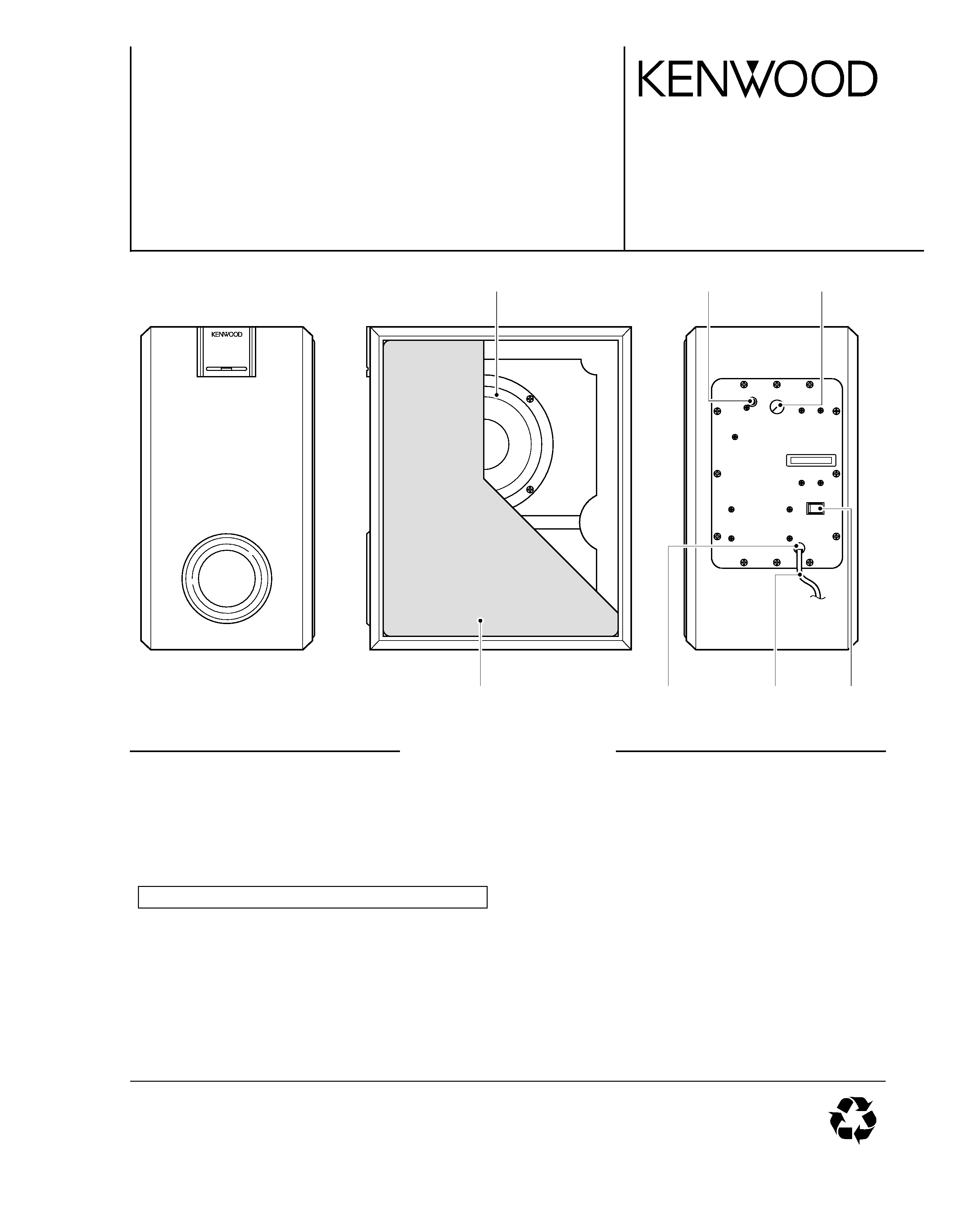
NOTE:THE GRILLE CANNOT BE REMOVED.
POWERED SUBWOOFER
SW-38HT/-38HT-B
SERVICE MANUAL
© 2004-6 PRINTED IN KOREA
B51-5905-00 (K/K) 876
70%
100W POWERED
SUBWOOFER
POWER ON
Woofer
(T10-1253-05)
RCA
(E63-0223-08)
Knob
(K29-0596-08)
Cloth frame *
(B06-)
AC Power cord *
(E30-)
Switch
(S66-0206-08)
AC Power cord bushing
(J42-0261-08)
SPECIFICATIONS
SW-38HT
2
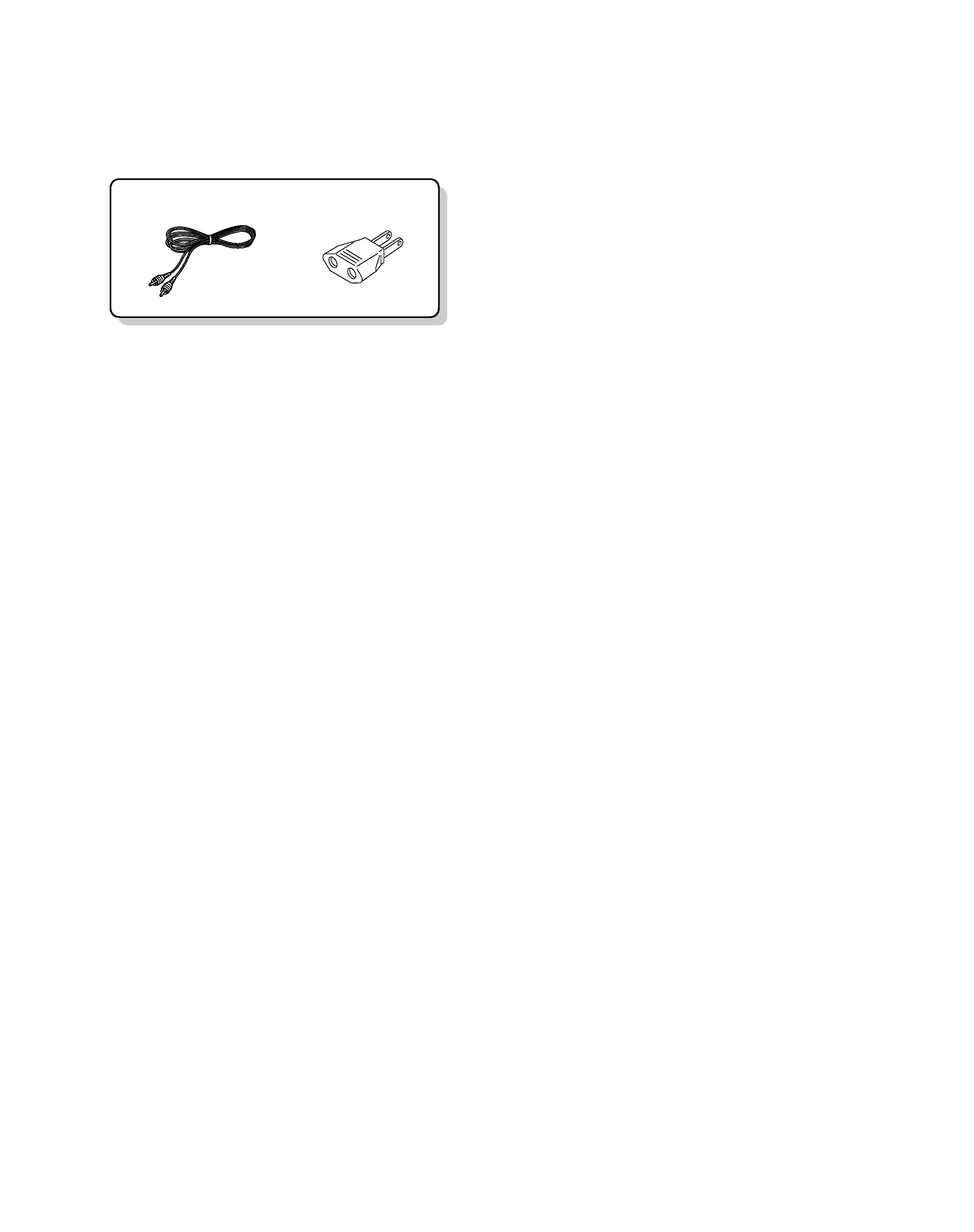
Pin-plug cord (1)
(E30-7068-05)
AC plug adapter(1)
(E03-0260-05)
ACCESSORIES
Accessories
How to Replace Woofer
Cut the cloth of cloth frame ass'y and replace it with new one after mount the speaker.
AC
E
BD
2
1
3
5
7
4
6
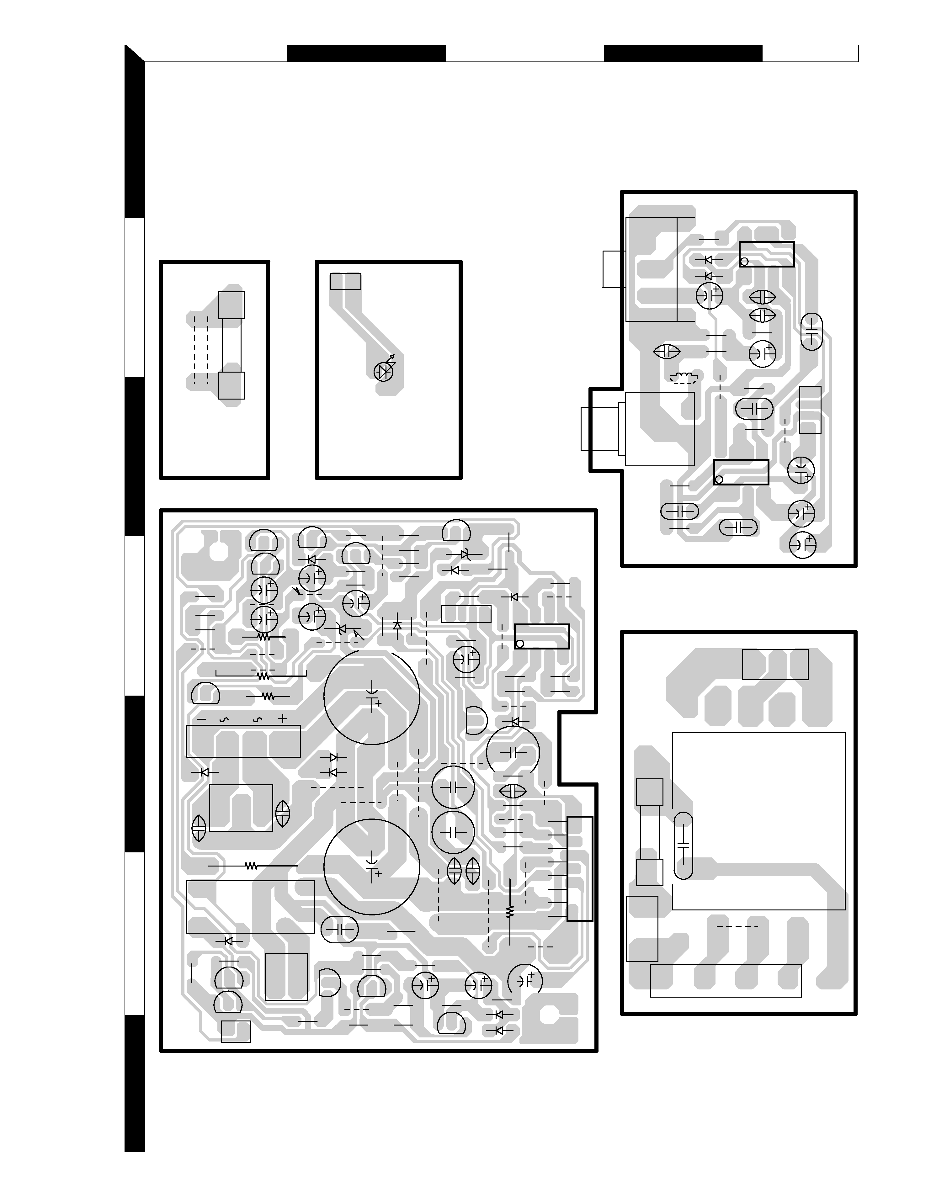
Refer to the schematic diagram for the value of resistors and capacitors.
PC BOARD (Component side view)
EC
EC
EC
EC
EC
EC
EC
EC
EC
EC
E
C
E
C
R41
R38
R42
R44
R43
C24
R39
R40
JW20
R9
JW15
JW11
C13
R11
R10
R15
JW7
R13
R14
JW27
R29
R31
C21
R25
R28
R26
JW17
R27
R30
C16
R32
R33
C20
C14
R24
R20
R17
R16
R21
JW14
R36
R23
R7
L1
JW27
C1
R2
VR1
R4
R1
R3
C4
C3
R5
C7
R6
C8
R8
C9
R19
R18
T1
JW 0
BLK
P2
41
15
10
6
12
14
2
14
15
1
21
1
3
12
1
85
14
85
1
21
4
85
14
14
3
JW25
JW26
R49
R45
R50
JW23
R51
JW22
JW24
R47
R48
JW10
R46
RL1
JW12
R34
R35
C19
JW21
JW13
JW9
C32
C31
JW8
C30
C15
C23
C22
C29
JW6
JW3
R21
JW5
JW4
C17
C18
R52
C28
C27
C26
C25
R37
JW1
JW2
C10
C2
JW19
JW18
F2
C6
C5
C1
1
C12
P1
BRN
C33
F1
JW16
D15
CN5
LED
I/O
MAIN
POWER SUPPLY
CN1
JK1
Q1
CN10
Q2
Q4
IC1
D2
D1
IC2
IC3
D16
D17
CN2
D4
D3
D12
D9
D10
D8
Q7
Q11
Q9
Q8
D11
Q12
D14
CN4
D13
CN3
D7
IC4
D6
CN9
Q3
Q5
D5
Q6
CN6
Q10
CN7
3
AC
E
BD
2
1
3
5
7
4
6
SW-38HT
SUB-IN
JK1
D2
(1/2)
IC1
D1
(2/2)
IC1
(2/2)
IC2
(1/2)
IC2
CN1
CN2
(1/2)
D3
D4
IC3
(2/2)
IC3
Q1
D6
D7
Q4
Q3
Q2
D5
Q6
Q5
CN3
D8
D10
D9
D11
Q10
Q11
Q12
Q9
Q8
Q7
D12
CN6
D14
D13
D17
D16
CN5
D15
SW1
POWER SW
CN4
CN10
CN7
USED
(K) (P) (E) (X) TYPE
CN9
S1
USED (Y) TYPE
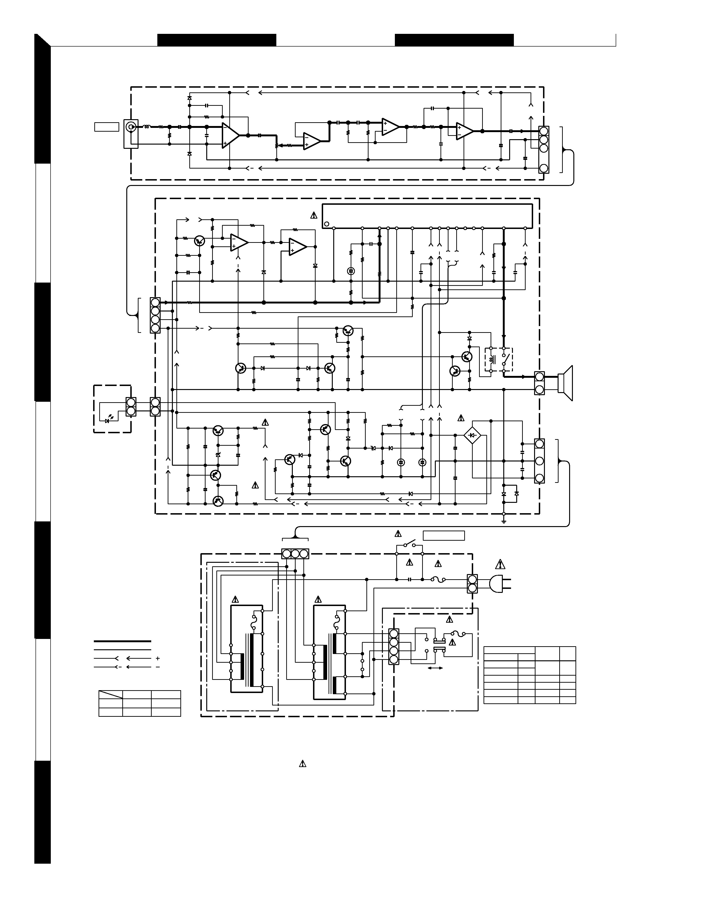
SIGNAL LINE
B LINE
B LINE
GND LINE
IC1-3 : TL072
IC4
: TDA7293V
Q1,3,4,6,8,9,11
: 2N3906
Q2,7 : 2N3904
Q5
: 2N5401
Q10
: MPSW06
Q12
: MPSW56
D1-9,11,13,16,17
: 1N4148
D12
: 1N5246B
D14
: KBU4D
D10
: 1N5240B
P1
P2
L1
22K
R2
22u25
+
C2
100P
C4
8
2
4
3
1
C3 1000P
R3 47K
6
5
7
1K
R4
10K(B)
VR1
10u50
+
C5
5
6
7
2
3
1
4
8
22K
R7
0.033
C9
22K
R8
0.068
C8
C6 C7
R5 10K
R6
10u50
+
C10
1
2
3
4
1
2
3
4
47u25
C1
1
+
47u25
C12
+
8
2
4
3
1
R18
R19
10K
R21
1K
R20
2.2K
R15
10K
R23
R17
5
6
7
4.7u50
C19
100K
R16
10K
+
22K
390
1
2
3
4
5
6
7
8
9
10
11
12
13
14
15
C15
47u50
390
R13
C16
1
R14
3.9
2W
22K
R12
1K
R10
47u50
C14
+
9
10
1K
R9
R52
R32
R31
10u50
C21
1K
R30
47u25
C20
+
4.7K
R28
10K
R29
100K
22K
+
10K
R25 47K
R26 47K
10K
R27
68
R33
1
2
RL1
22K
R37
C23
10u50
100K
R38
33K
R34
22K
R35
C22
10u50
4.7K
R36
22K
R41
22K
R42
R40
R39
R44
22K
R43
10u50
C24
+
2.2K
R49
47u25
C26
+
2.2K
R48
+
R51
+
R50
1/4W
1/4W
470
R47
2W
2W
470
R46
47u25
C28
9.1K
47u25
C27
10K
22K
22K
+
C25
1u50
47K
9
10
1
2
3300u50
C30
3300u50
C29
++
6.8K
R45
3
1
2
0.047
C32
0.047
C31
2
1
1
2
(K,P) : AC120V 60Hz
50/60Hz
: AC110-120V/220-240V~
: AC230V~ 50Hz
: AC100V~ 50/60Hz
(J)
(E)
(Y)
5
6
4
3
2
1
8
10
9
7
10
9
6
7
8
2
1
3
4
5
F1
BLK
WHT
0.01
C33
T1
13
2
1
2
3
4
T1.25AL 250V
220-240V
110-120V
B
+B
T2
JW
0
: AC240V~ 50Hz
(X)
F2
T2AL
T2A
T1.25AL
T2.5A
F1
T1.25AL
AUSTRALIA
EUROPE
JAPAN
E
X
J
DESTINATION
COUNTRY
U.S.A.
CANADA
PX
ABB.
Y
P
K
NO
YES
NO
NO
NO
JW 0
39K
R1
1/4W
22K
R1
1
47K
R24
C17
0.047
C18
0.047
C13
47P
B
+B
B
+B
+B
B
B
+B
+B
B
+B
B
+B
B
B
+B
+B
B
+B
B
+B
IC4
I/O
MAIN
LED
SW-38HT
POWER SUPPLY
SW-38HT
K,P
EXYJ
C6,7
0.068
0.68
R6
270K
18K
CAUTION: For continued safety, replace safety critical components only with
manufacturer's recommended parts (refer to parts list).
indicates safety crit-
ical components. For continued protection against risk of fire, replace only
with same type and rating fuse(s). To reduce the risk of electric shock, leak-
age-current or resistance measurements shall be carried out (exposed parts
are acceptably insulated from the supply circuit) before the appliance is
returned to the customer.
The DC voltage is an actual reading measured
with a high impedance type voltmeter with no
signal input. The measurement value may vary
depending on the measuring instruments used
or on the product.
4
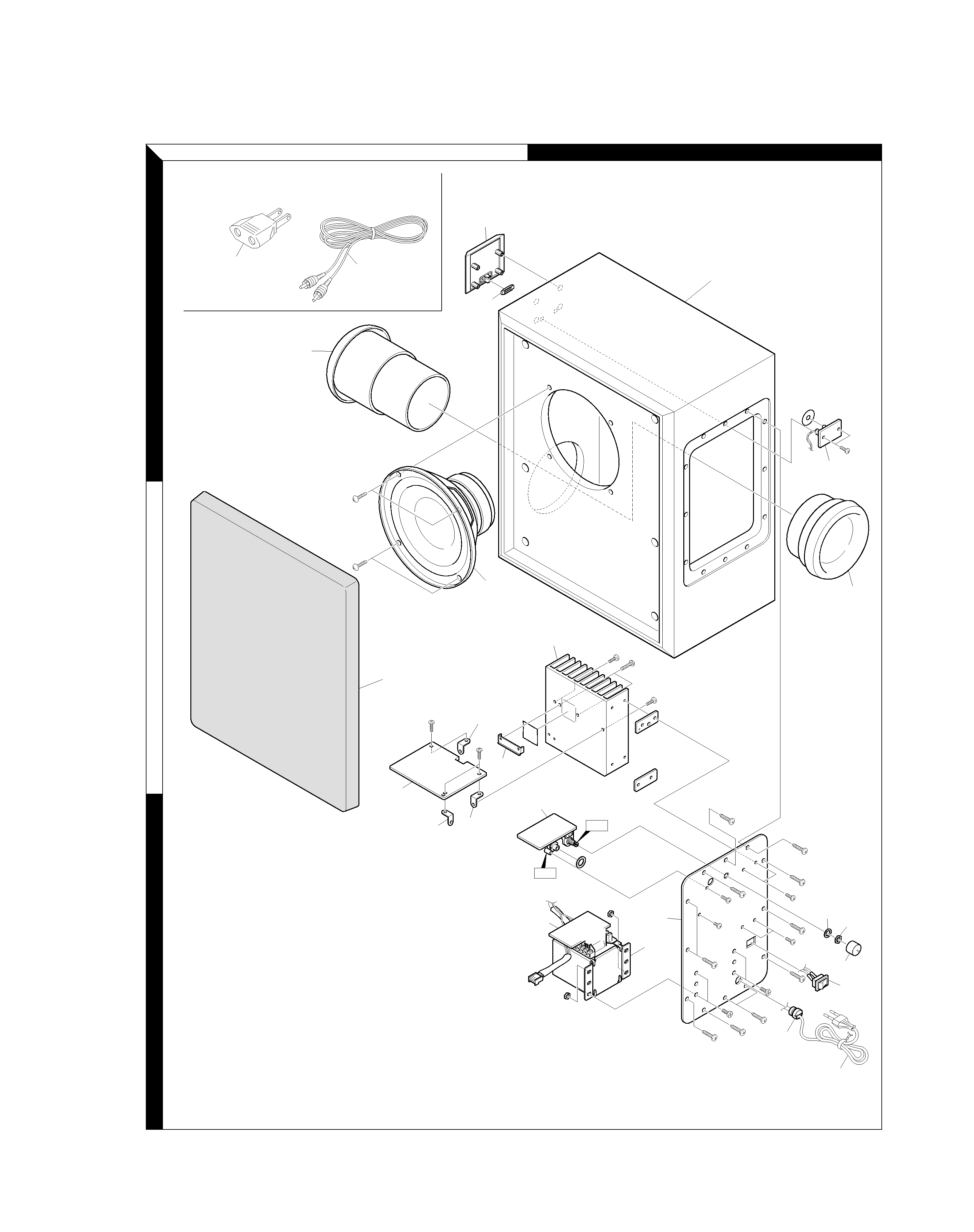
EXPLODED VIEW
Parts with exploded numbers larger than 700 are not supplied.
SW-38HT
706
605
711
T1 or
T2
752
711
754
713
603
601
610
SW1
708
715
753
711
714
700
751
709
707
JK1
INPUT
VR1
VOLUME
SP1
B
C
D
E
F
G
H
: N44-3010-45
:
:
:
:
:
:
N44-4016-45
N44-4010-45
N86-3006-45
N86-3010-45
N86-3014-45
N10-2040-46
3x10(BLK)
4x16(BLK)
4x10(BLK)
3x6(BLK)
3x10(BLK)
3x14(BLK)
N4
POWER
SUPLY PCB
LED PCB
MAIN PCB
I/O PCB
Bx2
Fx2
Hx2
Hx2
Gx2
Cx2
Dx2
Dx2
Cx2
Bx2
B
C
E
C
C
C
C
C
F
F
F
C
C
Cx2
Cx2
Bx2
702
712
604
616
1
2
3
A
B
SW-38HT
5