COMPACT Hi-Fi COMPONENT SYSTEM
RXD-M47MP
SERVICE MANUAL
(HM-437MP)
© 2004-10 PRINTED IN KOREA
B51-5934-00 (K/K) 715
70%
In compliance with Federal Regulations, following are repro-
duction of labels on, or inside the product relating to laser
product safety.
KENWOOD Corp. certifies this equipment conforms to DHHS
Regulations No.21 CFR 1040. 10, Chapter 1, subchapter J.
DANGER : Laser radiation when open and interlock defeated.
AVOID DIRECT EXPOSURE TO BEAM.
Caution : No connection of ground line if disassemble
the unit. Please connect the ground line on
rear panel, PCBs, Chassis and some others.
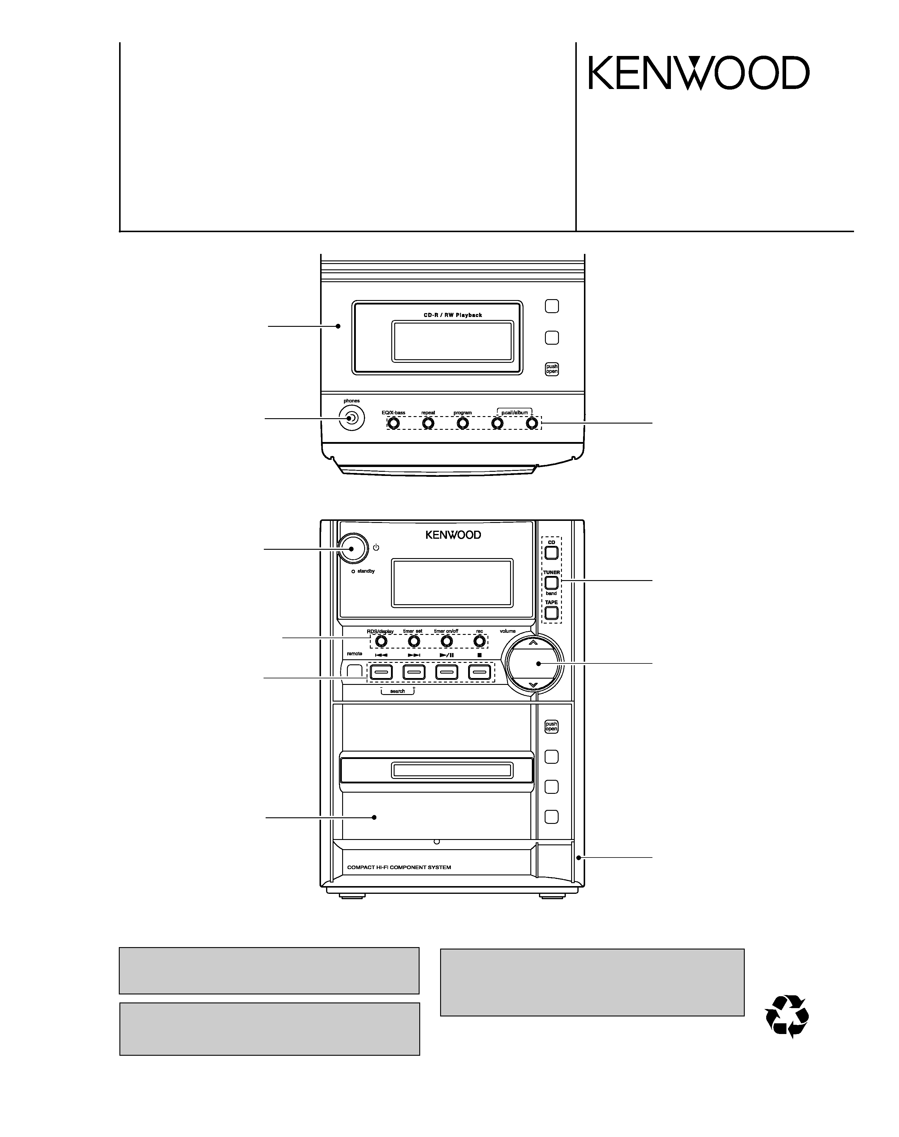
CD cover ass'y
(F07-2030-08)
Phone jack
(E63-1365-08)
Power knob
(K29-8426-08)
Display/Rec. knob
(K29-8428-08)
Search knob
(K29-8430-08)
Cass lid ass'y
(A53-2455-08)
Front cabinet
(A60-2427-08)
Volume knob
(K29-8429-08)
CD/Tuner/Tape knob
(K29-8431-08)
EQ/Bass knob
(K29-8427-08)
CONTENTS / ACCESSORIES / CAUTIONS ...............2
EXTERNAL VIEW ........................................................3
ADJUSTMENT .............................................................4
PC BOARD ..................................................................9
SCHEMATIC DIAGRAM ............................................13
EXPLODED VIEW .....................................................19
SPECIFICATIONS..................................BACK COVER
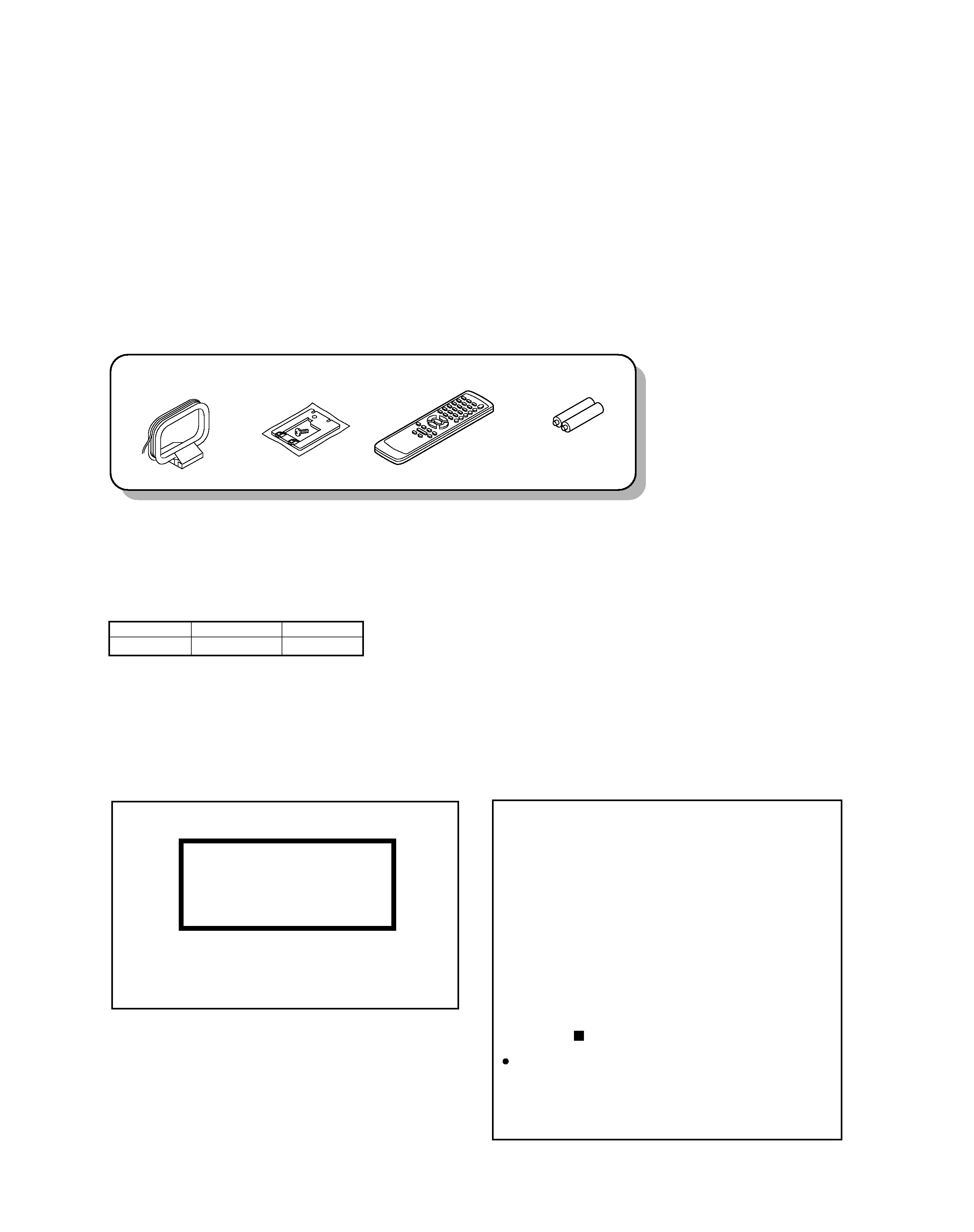
Remote control unit (1)
(A70-1692-08)
AM loop antenna (1)
(T90-0908-08)
ANT TERMI CVR
(F07-2029-08)
Batteries (R6/AA) (2)
()
Plug in the AC power cord to the wall out-
let, and within 5 seconds, press and hold
down the
button and press CD button.
The marking of products using lasers
The marking this product has been classified as Class 1. It
means that there is no danger of hazardous radiation out-
side the product.
Location: Bottom
CLASS 1 LASER PRODUCT
LASER KLASSE 1
APPAREIL A LASER DE CLASSE 1
LUOKAN 1 LASERLAITE
KLASS 1 LASERAPPARAT
Resetting the Microcomputer
The microcomputer may malfunction (unit can-
not be operated, or shows an erroneous dis-
play)if the power cord is unplugged while the
power is ON, or due to some other external
factor. If this happens, execute the following
procedure to reset the microcomputer and re-
turn the unit to its normal operating condition.
Please note that resetting the microcomputer
will clear the contents of the memory and
return the unit to the state it was in when it
left the factory.
RXD-M47MP
2
CONTENTS / ACCESSORIES / CAUTIONS
Accessories
Cautions
System configuration
SYSTEM
RECEIVER
SPEAKER
HM-437MP
RXD-M47MP
LS-M47
Contents
RXD-M47MP
3
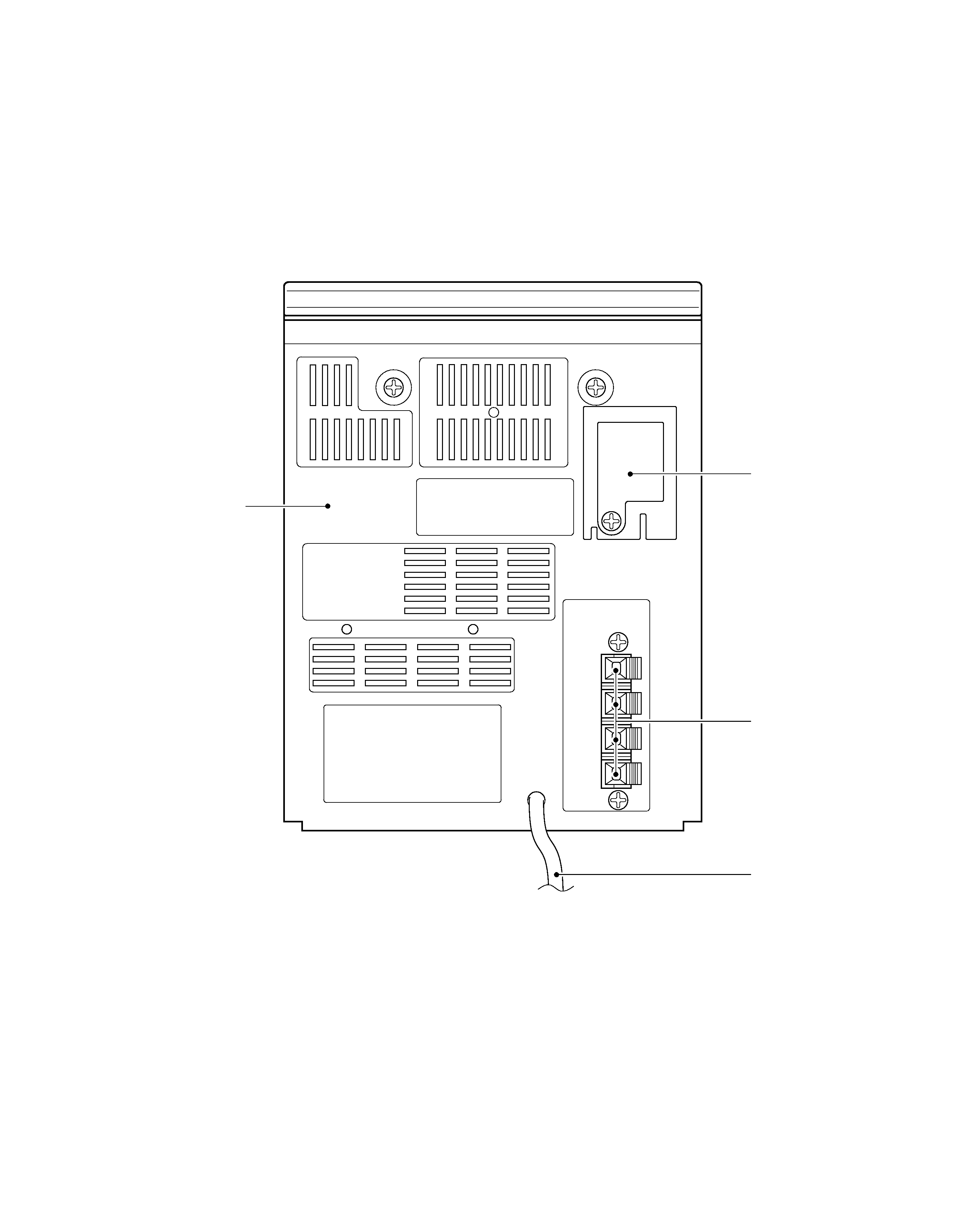
EXTERNAL VIEW
Rear cabinet
(A80-4503-08)
Antenna cover
(F07-2029-08)
Speaker terminal
(E70-0196-08)
AC power cord
(E30-7343-08)

RXD-M47MP
4
ADJUSTMENT
SERVICE ADJUSTMENT
Lubrication
The mechanical parts are factory coated with a thin coat of light grease and should not require further
lubrication. If a light grease is applied, be careful not to get any grease on the play/record head or erase
head, hubs, pulleys, tapes reels, drive belts, or switches. Use a good lubricant such as Silicon Lube G322L
or Lubricate.
Service Check
Before aligning the mechanism, wipe off any accumulated dirt with denatured alcohol. Wipe around parts
where the tape contacts and around all rotating parts. Drive belts are specially processed. Do not clean
them with alcohol.
Mechanical Torque
Use a cassette type torque gauge and check the tape mechanism.
Take-up torque
35 to 70 g-cm
Rewind torque
50 g-cm min.
Fast forward torque
50 g-cm min.
Pinch Wheel Pressure
No adjustment to the pinch roller spring is necessary. It should be sufficient to give at least 40 g-cm pull
force.
Tape Head Servicing
Each time the unit is serviced, the face of all heads should be thoroughly cleaned with denatured alcohol or
commercial head cleaning solution. The playback head should be demagnetized with a commercial
demagnetizer. Accumulation of tape oxide during normal operations can cause problems, including loss of
high frequencies and wow and flutter.
Erase Head
The erase head is properly aligned when the tape rides directly between the tape guide on the head without
crinkling the tape.
RXD-M47MP
5
ADJUSTMENT
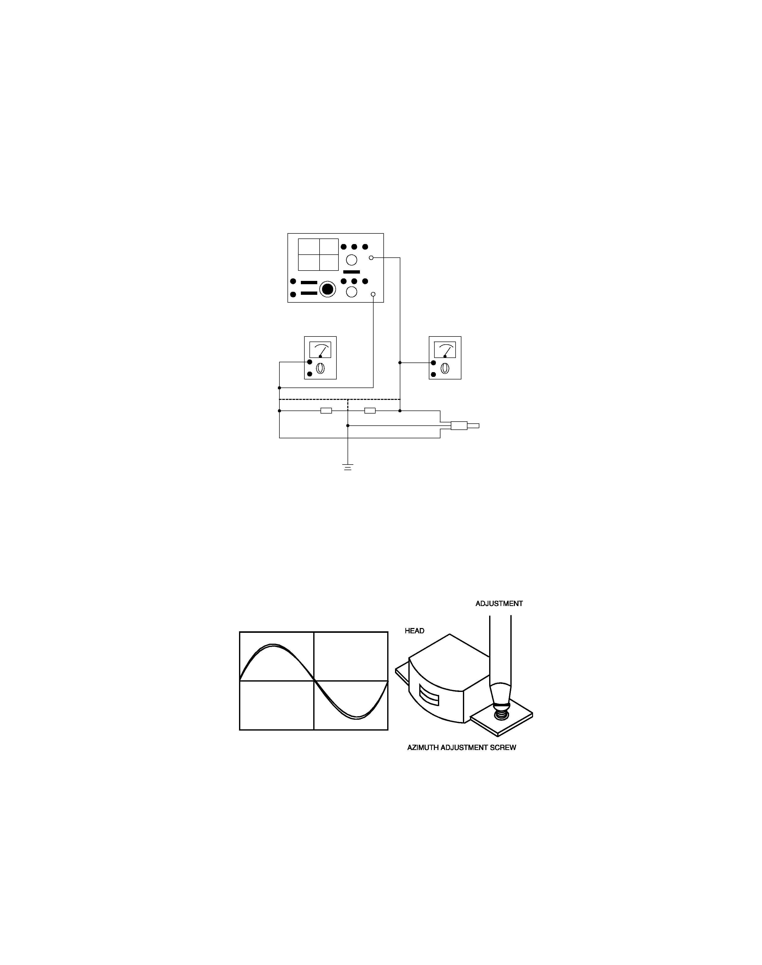
Play/Record and Playback Head Azimuth Adjustment
To adjust the play/record and playback head azimuth screw:
1. Connect two (2) VTVMs and a dual trace scope to the stereo headphone jack (as shown) with a 32
ohm dummy load. (See Figure 1.)
VTVM
VTVM
DUMMY LOAD
JK801
SCOPE
CH1
CH2
Figure 1. Azimuth Adjustment
2. Insert a 10 kHz test tape (Teac MTT-1141V or Equivalent) into the tape mechanism and play it back.
3. While playing back the test tape, slowly turn the azimuth adjusting screw until the amplitude of both
channel output waveforms is maximum and in phase. (See Figure 2.)
4. Secure the azimuth screw in place with glue or paint after making the adjustment.
Figure 2. Head Output Signal