(XD-A55/A75)
70%
MINI HiFi COMPONENT SYSTEM
RXD-A55/A75
SERVICE MANUAL
© 2001-4/B51-5713-00 (K/K) 1382
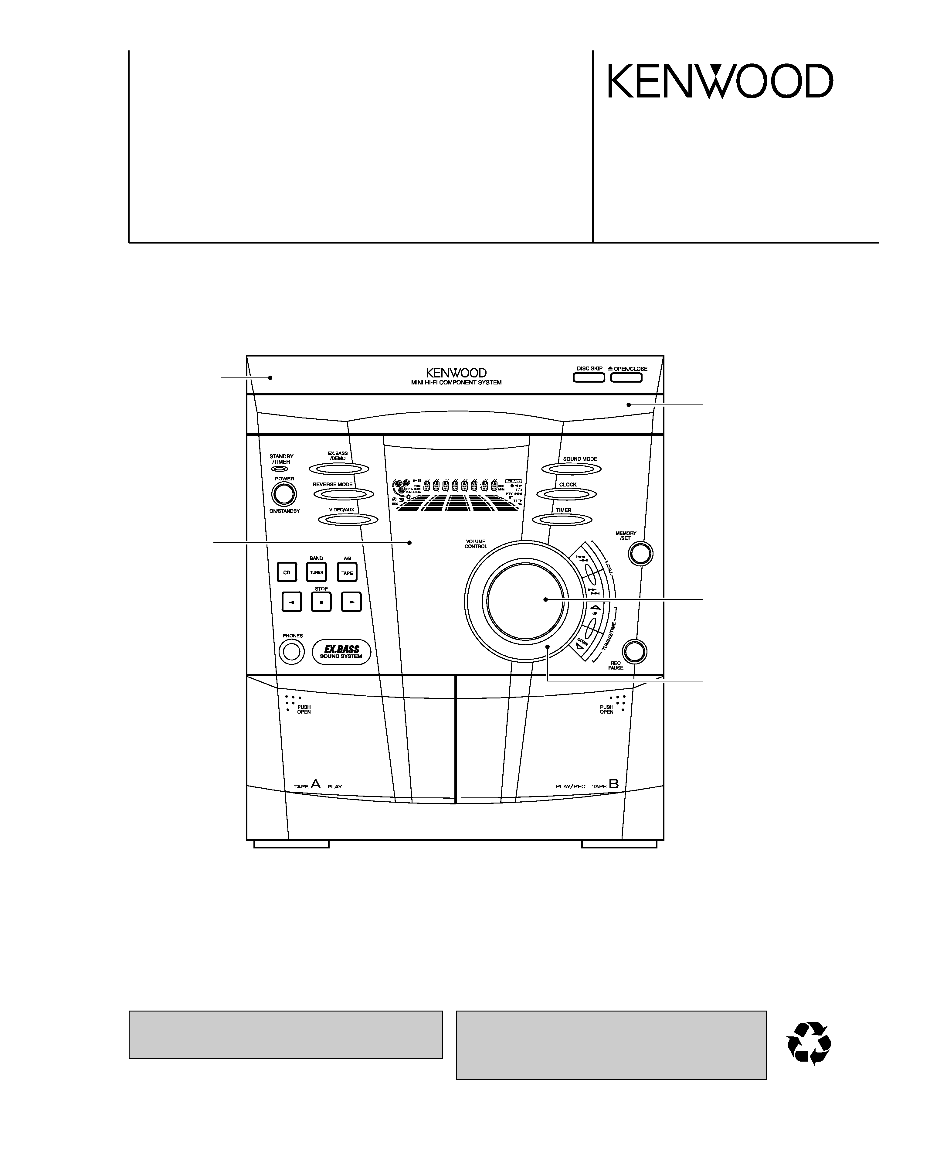
Panel ass'y
(A60-2091-08)
Knob(VOLUME)
(K27-2470-08)
Dress ring
(A21-3957-08)
In compliance with Federal Regulations, following are repro-
duction of labels on, or inside the porduct relating to laser prod-
uct safety.
KENWOOD-Crop. certifies this equipment conforms to DHHS
Regulations No.21 CFR 1040. 10, Chapter 1, subchapter J.
DANGER : Laser radiation when open and interlock defeated.
AVOID DIRECT EXPOSURE TO BEAM.
* Refer to parts list on page 33.
Panel(CD)
(A60-2090-08)
Front glass *
(B10-)
RXD-A55/A75
2
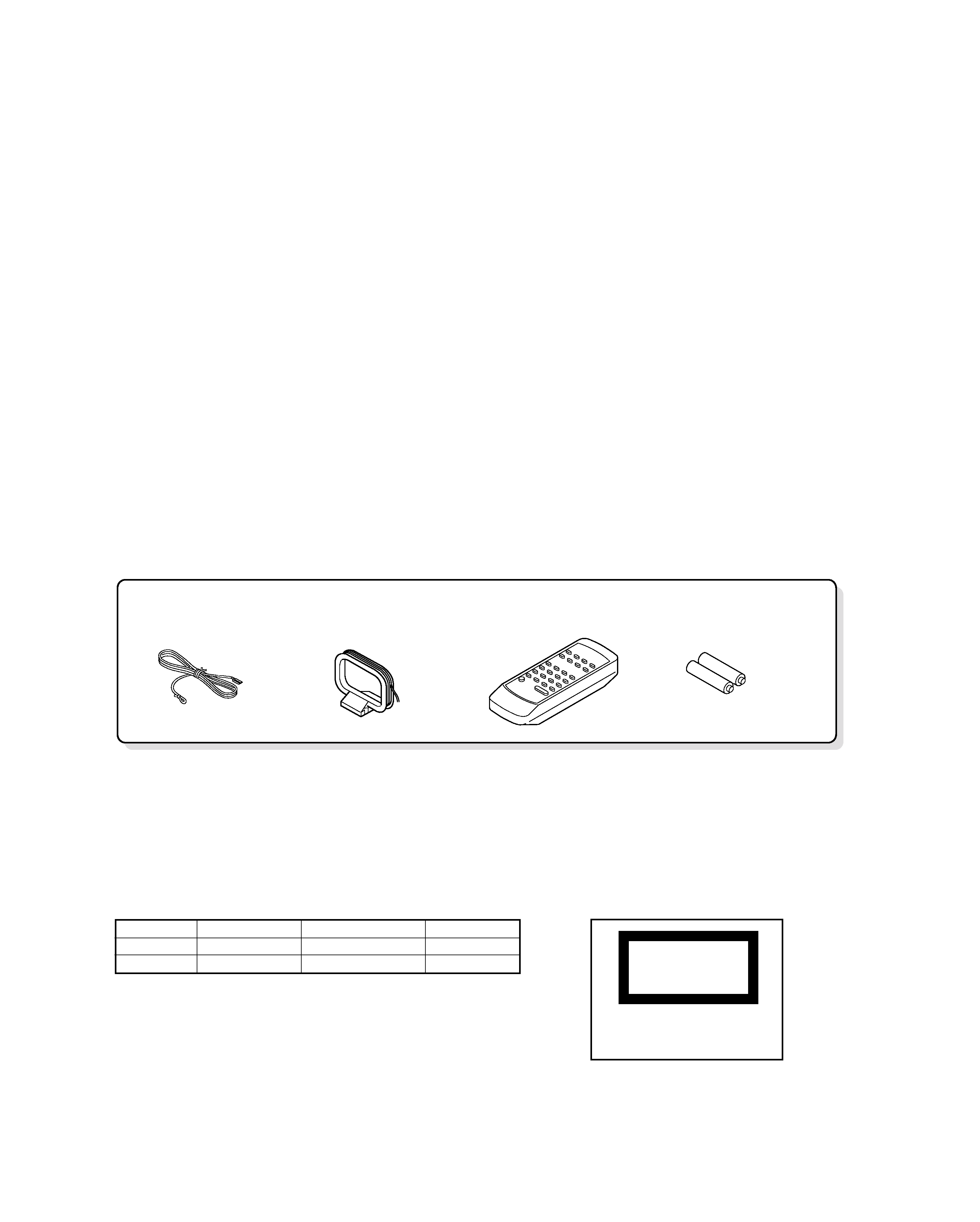
CONTENTS / ACCESSORIES
CONTENTS / ACCESSORIES .................................. 2
EXTERNAL VIEW .......................................................3
DISASSEMBLY FOR REPAIR....................................4
BLOCK DIAGRAM ......................................................9
CIRCUIT DESCRIPTION ..........................................11
ADJUSTMENT ..........................................................14
PC BOARD .............................................................. 16
SCHEMATIC DIAGRAM .......................................... 23
EXPLODED VIEW ....................................................31
PARTS LIST..............................................................33
SPECIFICATIONS ....................................................37
Contents
FM Antenna (1)
(T90-0883-08)
AM Loop Antenna (1)
(T90-0879-08)
Remote Control (1)
(A70-1531-08)
"AA" size battery (UM/SUM-3,
R6, HP-7 or similar)(2)
Accessories
SYSTEM CONFIGURATION
Cautions
SYSTEM
MAIN UNIT
DESTINATION
SPEAKER
XD-A55
RXD-A55
KP
LS-N50S
XD-A75
RXD-A75
KP
LS-N70S
CLASS 1
LASERPRODUCT
The marking
this
product
has been
classified
asClass
1.It
meansthat
there
isno danger
of hazardous
radiati
outside t
heproduct.
RXD-A55/A75
3
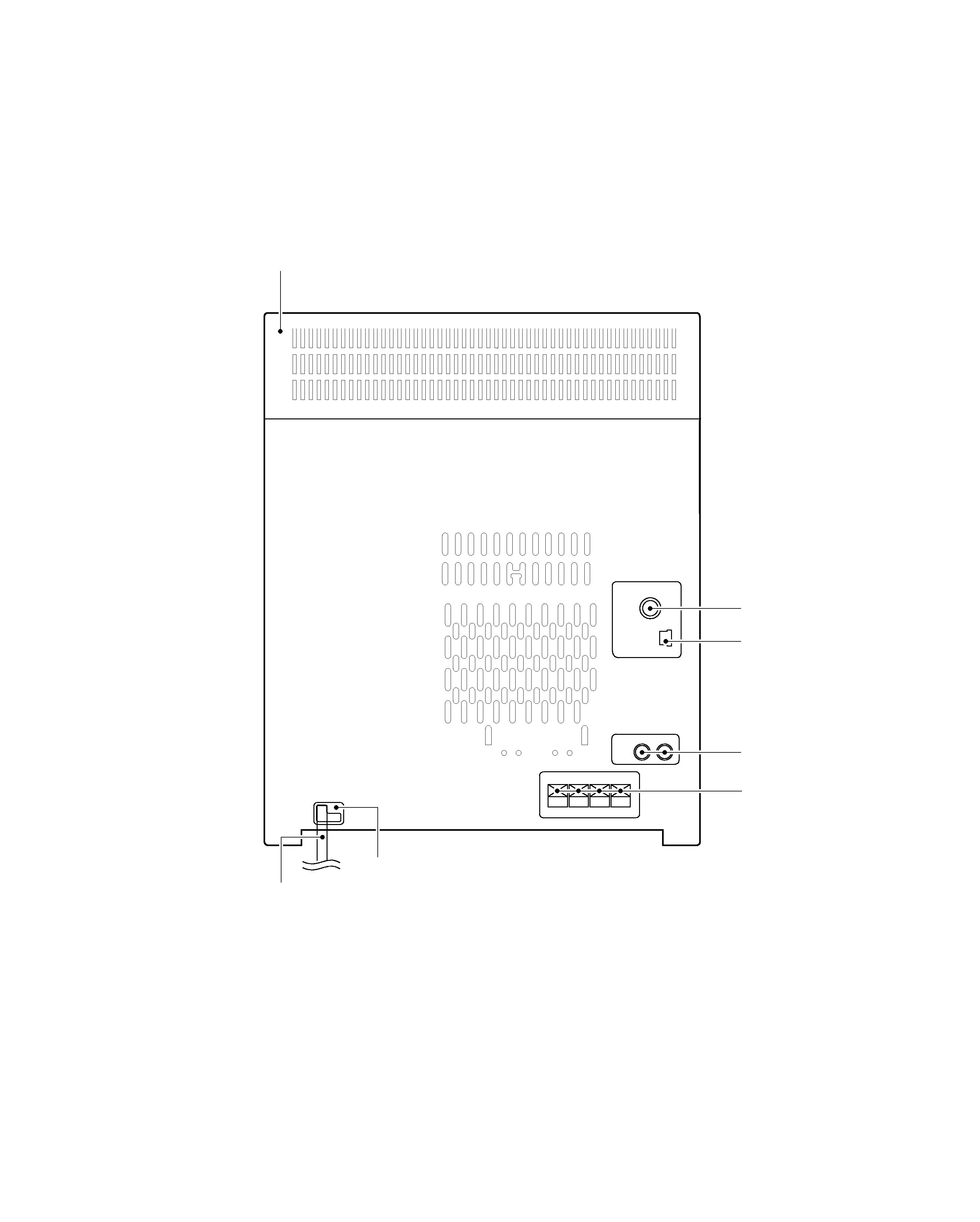
EXTERNAL VIEW
ANTENNA
FM
75
AM LOOP
R
SPEAKERS
+
+-
RL
-
VIDEO
/AUX
L
Pin jack
(E63-1219-08)
Pin ass'y
(E40-8933-08)
Cabinet(TOP)
(A02-3014-08)
Lock terminal board
(E70-0144-08)
AC power cord bushing
(J42-0351-08)
AC power cord
(E30-7222-08)
FM Antenna
(E70-0145-08)
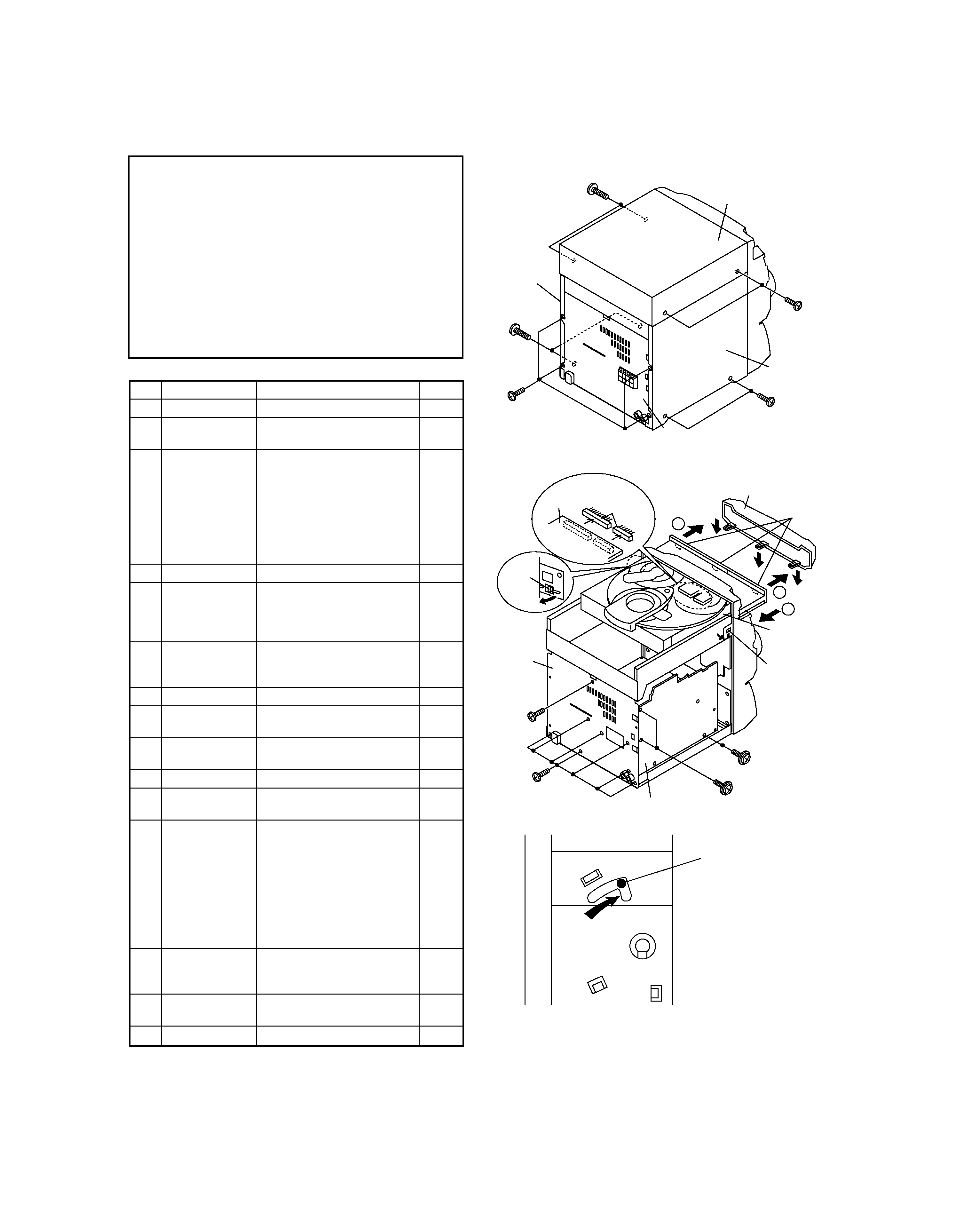
Caution on Disassembly
Follow the below-mentioned notes when disassembling
the unit and reassembling it, to keep it safe and ensure
excellent performance:
1. Take cassette tape and compact disc out of the unit.
2. Be sure to remove the power supply plug from the wall
outlet before starting to disassemble the unit.
3. Take off nylon bands or wire holders where they need be
removed when disassembling the unit. After servicing
the unit, be sure to rearrange the leads where they were
before disassembling.
4. Take suffcient care on static electricity of integrated
circuits and other circuits when servicing.
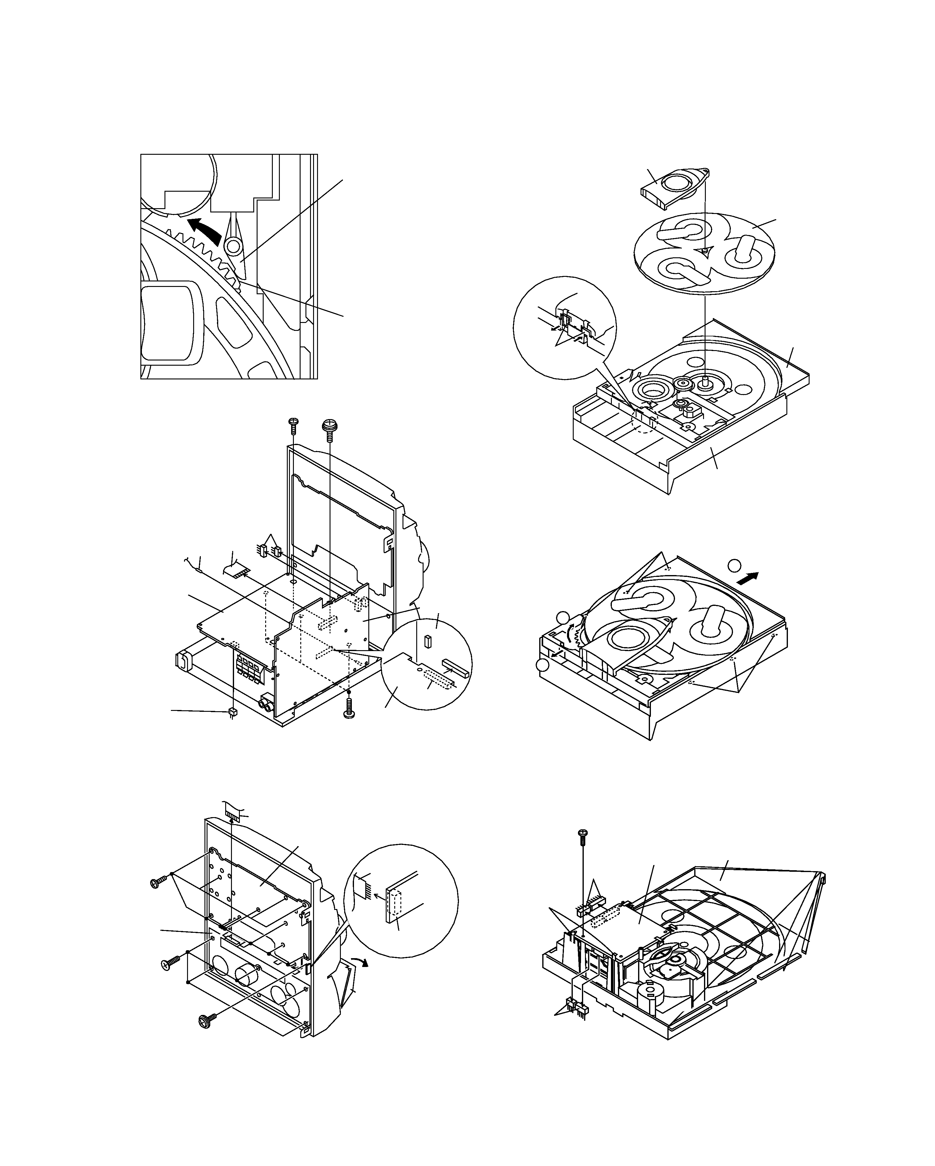
Figure 7-2
Figure 7-3
1
Top Cabinet
1. Screw ..................... (A1) x4
7-1
2
Side Panel
1. Screw ..................... (B1) x8
7-1
(Left/right)
3
CD Player Unit/
1. Turn on the power supply,
7-2
CD Tray Cover
open the disc tray, take out
the CD cover, and close.
(Note 1)
2. Screw ..................... (C1) x1
3. Hook ....................... (C2) x3
4. Hook ....................... (C3) x2
5. Socket .................... (C4) x2
4
Rear Panel
1. Screw ..................... (D1) x9
7-2
5
Main PWB
1. Screw ..................... (E1) x1
7-2
2. Socket .................... (E2) x3
8-2
3. Flat Cable .............. (E3) x1
4. Tip Wire .................. (E4) x1
6
Power Supply PWB 1. Screw ..................... (F1) x2
8-2
2. Socket .................... (F2) x1
3. Flat Wire ................. (F3) x1
8-3
7
Front Panel
1. Screw ..................... (G1) x3
8-2
8
Display PWB
1. Screw ..................... (H1) x9
8-3
2. Socket .................... (H2) x1
9
Tape Mechanism 1. Open the cassette holder.
8-3
2. Screw...................... (J1) x5
10
Headphones PWB 1. Screw ..................... (K1) x1
8-3
11
Turntable
1. Hook ....................... (L1) x2
8-4
2. Cover ..................... (L2) x1
12
Disc Tray
1. Turn fully the lock lever in the
7-3
arrow direction.
2. While holding the lock lever,rotate
8-1
the cam gear until the cam gear
rib engages with the clamp lever.
3. Push the slide holder backward to
8-5
engage the claw with the groove
and remove it in the direction
of the arrow. .............. (M1) x6
13
CD Servo PWB
1. Screw ..................... (N1) x1
8-6
(Note 2)
2. Hook ....................... (N2) x2
3. Socket .................... (N3) x4
14
CD Mechanism
1. Hook ....................... (P1) x2
9-1
2. Hook ....................... (P2) x3
15
Loading Motor PWB 1. Hook ....................... (Q1) x5
9-1
STEP
REMOVAL
PROCEDURE
FIGURE
Figure 7-1
(B1)x4
ø3x10mm
(B1)x2
ø3x10mm
Rear
Panel
(B1)x2
ø3x10mm
Side Panel
(Right)
Side Panel
(Left)
(A1)x2
ø3x12mm
(A1)x2
ø3x12mm
Top Cabinet
(E1)x1
ø3x10mm
(C3)x1
(D1)x2
ø3x10mm
(C1)x1
ø3x10mm
(D1)x7
ø3x10mm
CD Player
Unit
DC Tray Cover
Rear
Panel
Pull
(C3) x1
(C4)x2
(C2) x3
1
1
2
Main PWB
CD Servo
PWB
Note 1:
How to open the changer manually. (Fig. 7-3)
1. In this state, turn fully the lock lever in the arrow direction
through the hole on the loading chassis bottom.
2. While holding the lock lever, rotate the cam gear anticlockwise
until the cam gear rib engages with the clamp lever. (Fig. 8-1)
3. After that, push forward the CD slide holder.
Note 2:
1. After removing the connector for the optical pickup from the
connector, wrap the conductive aluminium foil around the
front end of the connector so as to protect the optical pickup
from electrostatic damage.
Note 3:
1. Be careful not to break the claw of the CD mechanism.
2. When fining back the cam gear assembly, let it lock by front
movement.
LOCK LEVER
RXD-A55/A75
4
DISASSEMBLY FOR REPAIR
RXD-A55/A75
5
DISASSEMBLY FOR REPAIR
Figure 8-1
Figure 8-2
Figure 8-3
Figure 8-4
Figure 8-5
Figure 8-6
CLAMP LEVER
CAM GEAR RIB
(F1)x1
ø3x6mm
(G1)x3
ø3x10mm
(F1)x1
ø3x10mm
(F2)x1
(E3)x1
(E4)x1
(E2)x2
Main PWB
(E2)x1
Power
Supply
PWB
Power
Supply
PWB
(H1)x9
ø3x10mm
(H2)x1
(J1)x5
ø3x10mm
(K1)x1
ø3x10mm
(F3)x1
Display PWB
Headphones
PWB
Open
Cassette
Holder
Tape
Mechanism
Turntable
Disc Tray
(L2) x1
CD Player Unit
(L1) x2
1
3
2
(M1) x3
(M1) x3
(N3) x2
(N2) x2
(N3) x2
CD Servo
PWB
CD Player
Base
(N1)x1
ø3x8mm