MICRO Hi-Fi COMPONENT SYSTEM
RD-HD5MD/HD7
SERVICE MANUAL
(HD-5MD/HD-7)
© 2002-11 PRINTED IN KOREA
B51-5835-00 (K/K) 3430
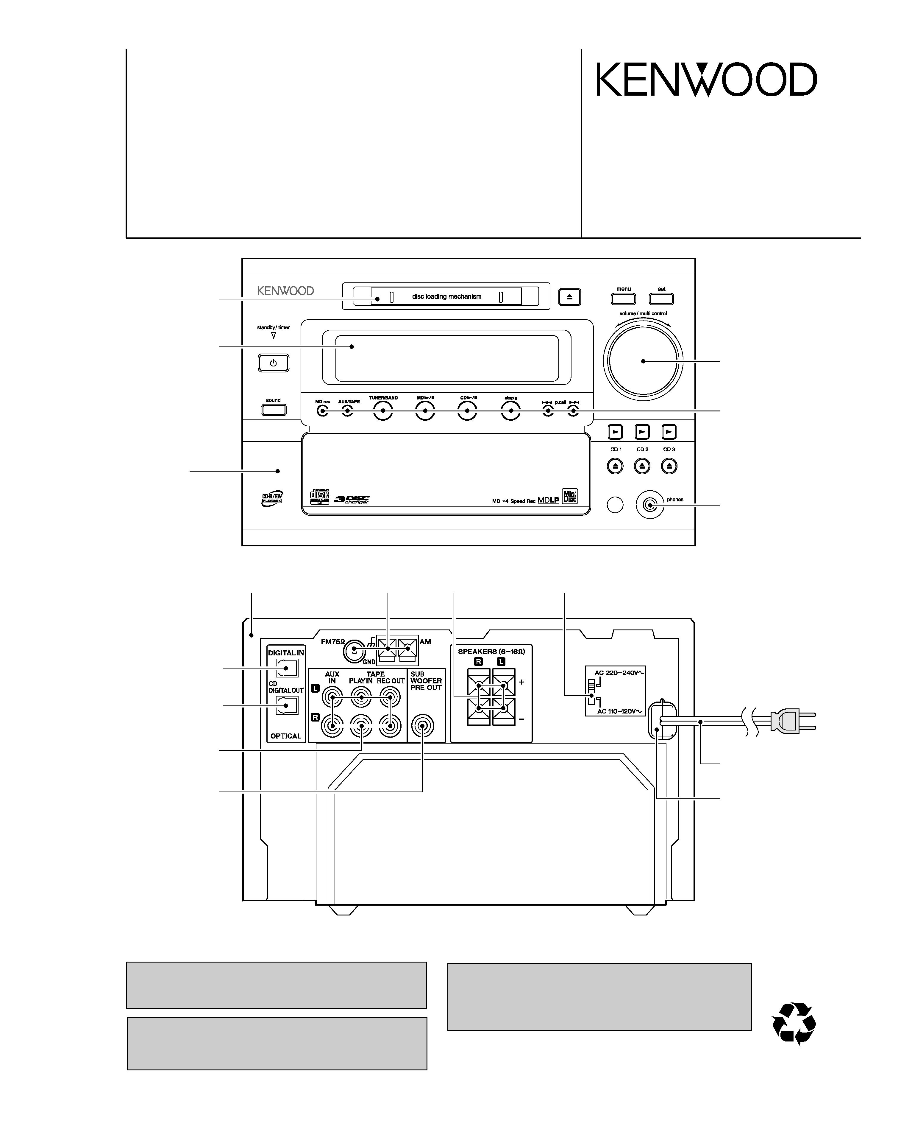
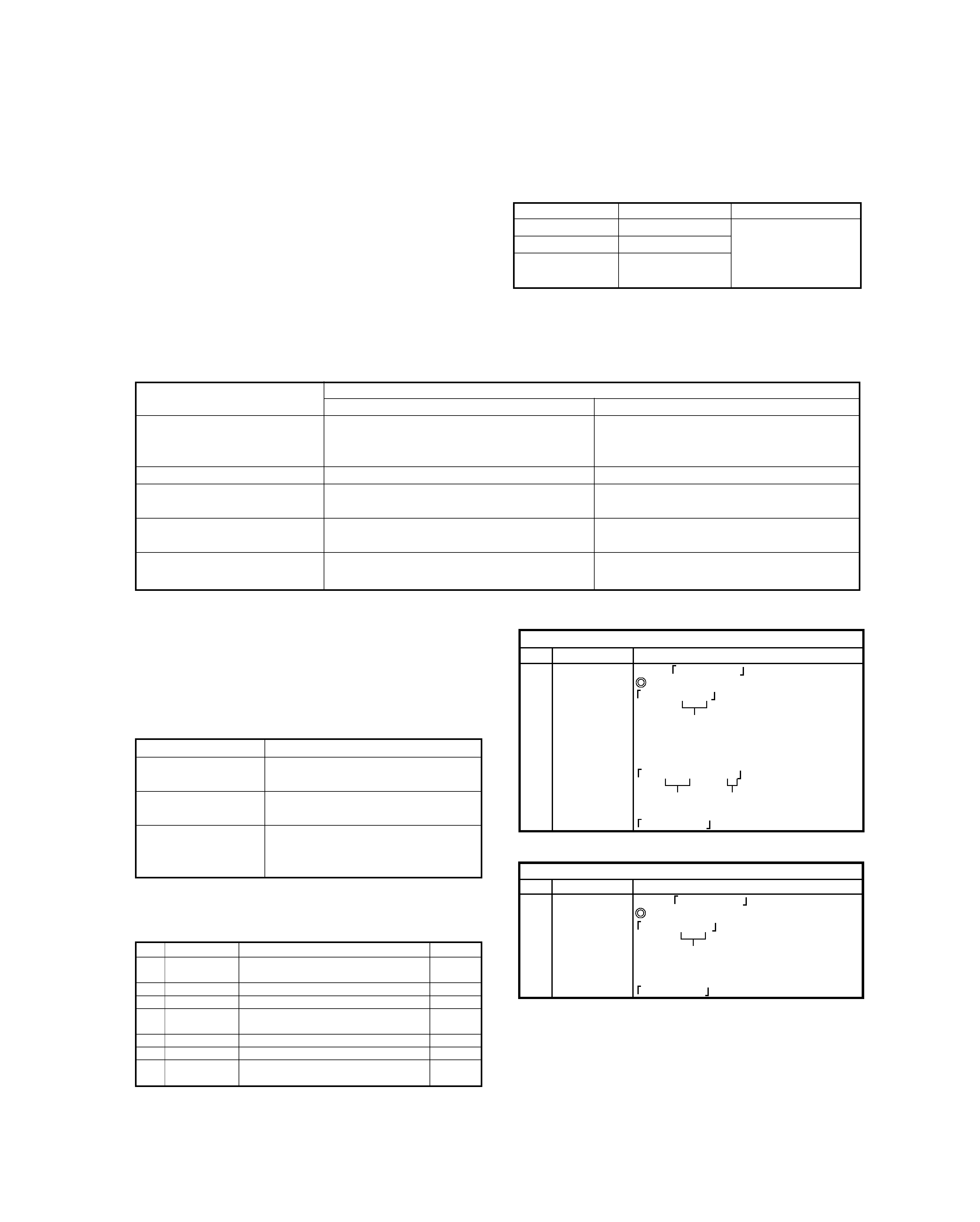
Door(MD)
(A52-0989-08)
In compliance with Federal Regulations, following are repro-
duction of labels on, or inside the product relating to laser
product safety.
KENWOOD Corp. certifies this equipment conforms to DHHS
Regulations No.21 CFR 1040. 10, Chapter 1, subchapter J.
DANGER : Laser radiation when open and interlock defeated.
AVOID DIRECT EXPOSURE TO BEAM.
Caution : No connection of ground line if disassemble
the unit. Please connect the ground line on
rear panel, PCBs, Chassis and some others.
Button
(K29-8274-08)
Knob(VOLUME)
(K29-8275-08)
Jack,D3.5
(E11-0969-08)
Window *
(B10-3934-08)
Panel *
(A60-)
Ter,RCA
(E63-0187-08)
Module
(W02-2802-05)
Module
(W02-2803-05)
Ter,RCA
(E63-1181-08)
Cabinet *
(A01-)
Tuner *
(W02-)
SW, Push block
(E21-0041-08)
SW, Slide *
(S62-0098-08)
Cord ass'y *
(E30-)
Stopper(AC cord)
(J42-0355-08)
* Refer to parts list on page 41.
Illust. is RD-HD5MD.
70%
RD-HD5MD/HD7
2
CONTENTS / ACCESSORIES / CAUTIONS
CONTENTS / ACCESSORIES / CAUTIONS ............. 2
EXTERNAL VIEW .......................................................3
DISASSEMBLY FOR REPAIR / ADJUSTMENT.........4
CIRCUIT DESCRIPTION ............................................5
PC BOARD .............................................................. 18
SCHEMATIC DIAGRAM .......................................... 24
EXPLODED VIEW ....................................................36
PARTS LIST..............................................................41
SPECIFICATIONS ....................................................51
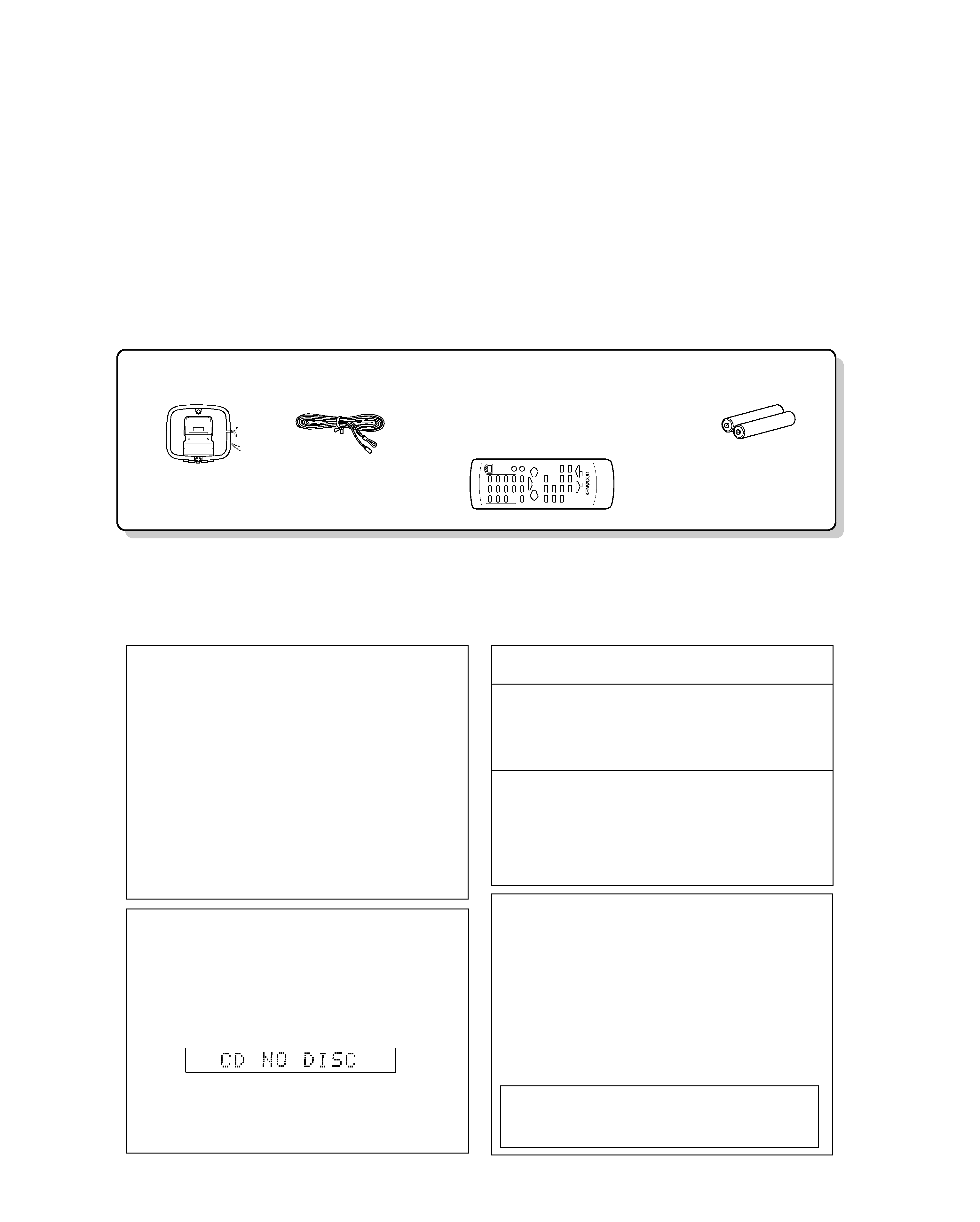
Contents
FM indoor antenna (1)
(T90-0904-08)
AM loop antenna (1)
(T90-0903-08)
Remote control unit (1)
(A70-1625-08): RD-HD5MD(T)
(A70-1626-08): RD-HD5MD(M), RD-HD7(V)
(A70-1629-08): RD-HD7(E,T)
(A70-1630-08): RD-HD7(K)
Batteries (R6/AA) (2)
Accessories
1 Remove the CD from the unit.
2 Press the CD6 key.
3 Wait for some time and verify that the dis-
play appears as above.
4 Wait a few seconds and turn the unit OFF.
Note related to transportation and
movement
Before transporting or moving this unit, carry out
the following operations.
Condensation (of dew) may occur inside the unit when
there is a great difference in temperature between this
unit and the outside.
This unit may not function properly if condensation oc-
curs. In this case, leave the unit for a few hours and
restart the operation after the condensation has dried
up.
Be specially cautious against condensation in a follow-
ing circumstances:
When this unit is carried from one place to another
across a large difference in temperature, when the hu-
midity in the room where this unit is installed increases,
etc.
Caution on condensation
Memory backup function
Stored contents which are cleared immediately
when power plug is unplugged from power outlet :
Clock display
N.B. function
Stored contents which will back-up after power
plug is unplugged from power outlet:
State of power (on or standby), A, P, S, Last input
selection, AUX level, Volume control value, Balance
control, Receiving band, Frequency, Preset station,
Program Timer, TONE
Operation to reset
The microcomputer may fall into malfunction (impossibil-
ity to operate, erroneous display, etc.) when the power
cord is unplugged while unit is ON or due to an external
factor. In this case, execute the following procedure to
reset the microcomputer and return it to normal condi-
tion.
Unplug the power cord from the power outlet, then while
holding the set key on the main unit depressed, plug the power
cord again.
÷ Please note that resetting the microcomputer clears
the contents stored in and it returns to condition
when it left the factory.
Cautions
RD-HD5MD/HD7
3
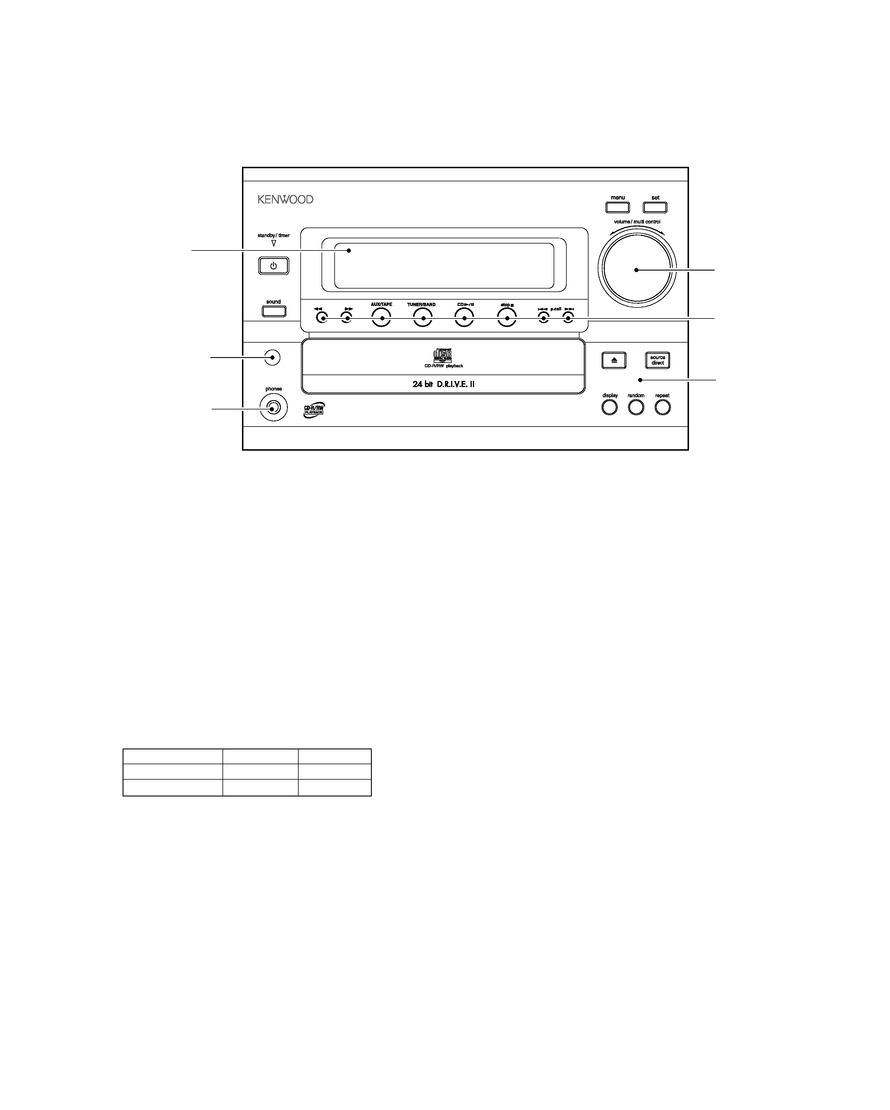
EXTERNAL VIEW
* Refer to parts list on page 41.
Illust. is RD-HD7.
SYSTEM CONFIGURATION
SYSTEM NAME
RECEIVER
SPEAKER
HD-5MD
RD-HD5MD
LS-HD7
HD-7
RD-HD7
LS-HD7
tuning
Front panel *
(A60-)
Knob *
(K29-)
Phone jack
(E11-0969-08)
Knob *
(K29-8274-08)
Window *
(B10-)
Window
(B11-1573-08)
RD-HD5MD/HD7
4
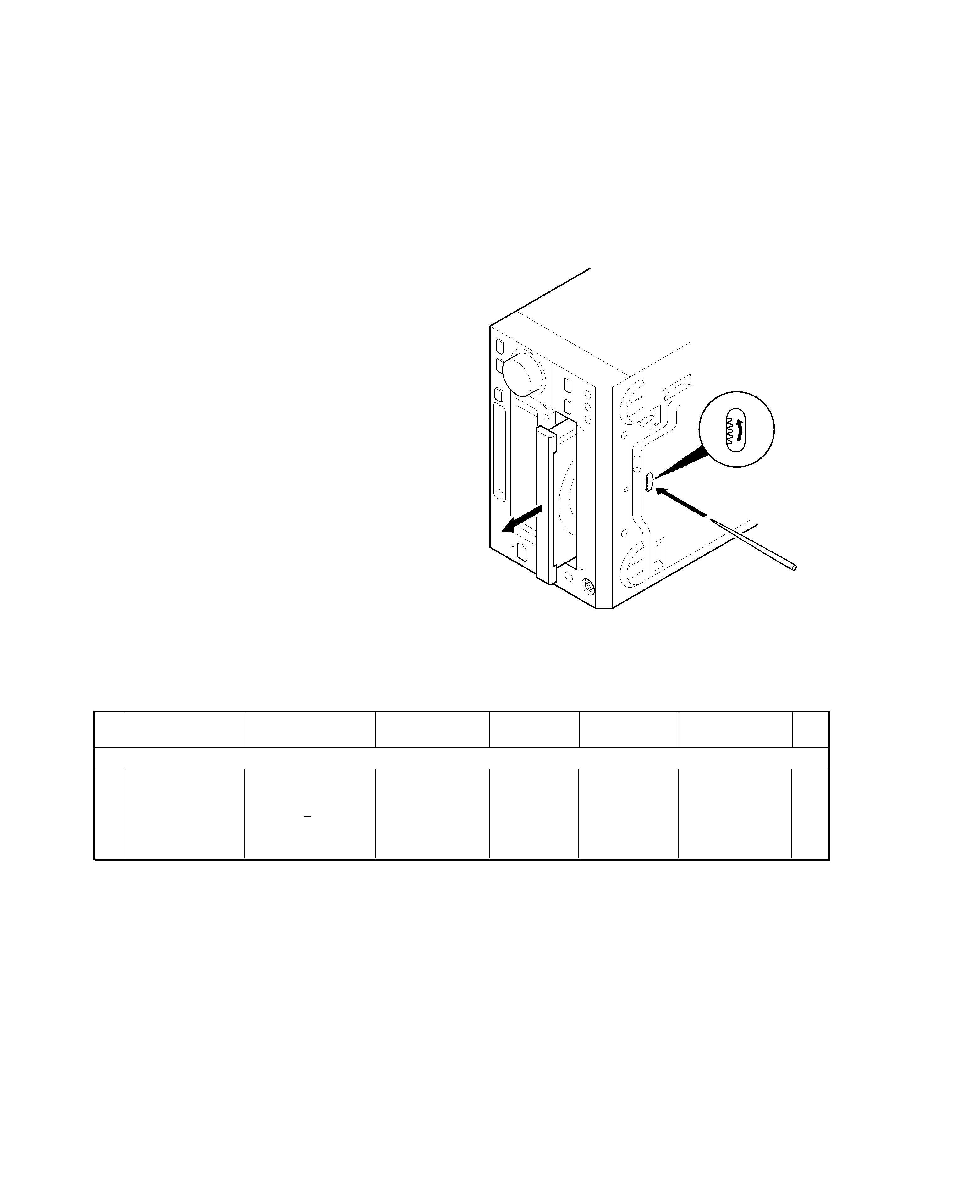
DISASSEMBLY FOR REPAIR / ADJUSTMENT
How to open the tray if it does not come out.
1. Turn the gear in the direction of the arrow using a bamboo stick and so on in the drawing through the hole on the loading chassis
bottom.
Note : Do not use a screw driver like a metallic instead of a bamboo stick.
(There is a danger of damaging the gear.)
2. Pull out the tray frontward by hand when it comes just out.
DISASSEMBLY FOR REPAIR
No.
ITEM
INPUT
SETTINGS
OUTPUT
SETTINGS
RECEIVER
SETTINGS
ALIGNMENT
POINTS
ALIGN FOR
FIG.
AUDIO SECTION :
SELECTOR : EXCEPT TUNER MODE
<1>
IDLE CURRENT
(RD-HD7 only)
Connect a DC
voltmeter to
CP901 or CP902
CP901 (Lch)
CP902 (Rch)
Volume:
Minimum
VR203 (Lch)
VR204 (Rch)
8 mV
ADJUSTMENT
RD-HD5MD/HD7
5
CIRCUIT DESCRIPTION
1. Initializing
1-1 Initializing Method
· While holding down the [SET] key, plugged in the
power cord to AC power wall outlet.
1-2 Initializing Operation
· During the initial operation, the display shows "INITIAL-
IZE "and after that it will be returned to standby condition.
2. Test Mode
2-1 Setting method of the Test Mode
2-2 Cancel of the test mode
· Initialized and cancel the test mode if pulling out the power cord.
Test Mode
Keys
Setting Method
CD Test Mode
CD PLAY PAUSE Insert the AC cord to
MD Test Mode
MD PLAY PAUSE AC wall outlet while
MD Mecha. Test
MD REC
holding down
Mode
the left key.
Operation
Key
CD Test Mode
MD Test Mode
CD-PLAY/PAUSE
(cyclically change the mode
Tracking-Servo ON/OFF
-
05 and 03 by pressing the key.
MENU
CD double speed CD normal speed
-
P.CALL UP
· CD Track number up
·The pickup travels outward in the stop mode.
MD Track number up
P.CALL DOWN
· CD Track number down
· The pickup travels inward in the stop mode.
MD Track number down
SET
-
Stop the MD operation, and start the ALL-
ERASE operation if the disc is recordable.
2-3 Operation of the Test Mode
KEYS
OPERATION
Volume/multi-control
Select the mode or changed
the adjustment value.
MD PLAY/PAUSE
Fix the mode or adjustment value.
Skip to next step.
Cancel the selected mode and
STOP
changed to menu page.
Return to the state previous before.
3. MD Test Mode for Adjustment
3-1 Contents of the Test Mode
3-2 Entering the Test Mode
· Turn the AC on while pressing the MD[REC] key.
3-3 Canceling the Test Mode
· Turn the AC off.
3-4 Key Operations for Adjustment
(1) Setting of Continuous Playback Mode
No.
Key
Display/Function
1
VOLUME
Select CREC-PLAY
2
Load a recordable disc.
3
(MD)
6
(MD)
6
CREC (ZZZZ) (CREC address)
0300h cluster = recording start point
ó
CPLAY ?
4
CPLAY MID
C = XXXX
a = YY (error)
C1 error
ADIP error
address MID = 0300h cluster
5
STOP
CREC-PLAY
ó
(1) Setting of Continuous Recording Mode
No.
Key
Display/Function
1
VOLUME
Select
CREC-PLAY
2
Load a recordable disc.
3
(MD)
CREC (ZZZZ) (CREC address)
0300h cluster = recording start point
CPLAY ?
4
STOP
CREC-PLAY
6
4. Electrical adjustment
4-1 Precaution during confirmation of Laser Diode
emission
During adjustment, do not view the emission of a laser
diode from just above for confirmation. This may dam-
age your eyes.
3-6 Continuous Playback Mode
3-7 Continuous Recording Mode
No.
LCD
DESCRIPTION
SECTION
1
TEMP ADJU
The work of adjustment is unnecessary
in this mode.
4-5
2
LDPWR ADJU
Laser power adjustment.
4-6
3
LDPWR CHEC Laser power check.
4-6
4
EFBAL ADJU
EF balance adjustment
(Traverse adjustment).
4-7
5
TE B. ADJ
Automatic EF balance adjustment.
4-8
6
FBIAS ADJU
Focus bias adjustment.
4-9
7
CREC-PLAY
Continuous recording mode.
3-7
Continuous playback mode.
3-6
3-5 Selection of Adjustment Test Mode
· Whenever the [volume/multi-control] knob is turned the
adjustment test mode is selected.
For more information on each adjustment mode, refer to
each section of 4, "Electrical adjustment".