
STEREO POWER AMPLIFIER
M-A300
M-A100
INSTRUCTION MANUAL
KENWOOD CORPORATION
This instruction manual is used for two models.
Model availability and features (functions) may differ depending on the country and
sales area.
B60-3340-00 (K, P, Y, T, M, C, X, I)
MA CH
MC
98/12 11 10 9 8 7 6 5 4 3 2 1 97/12 11 10 9 8 7 6 5
2
M-A300/A100 (En)
+
-
FRONT
CENTER
R
R
+
-
AC 110 -
120V~
AC 220 -
240V~
C
LL
UNSWITCHED
SW
FRONT SURROUND WOOFER
SUB
SURROUND
SPEAKERS
(6-16
)
SPEAKERS
(6-16
)
CONNECT WITH AV
CONTROL CENTER
AC 110 -
120V~
AC 220 -
240V~
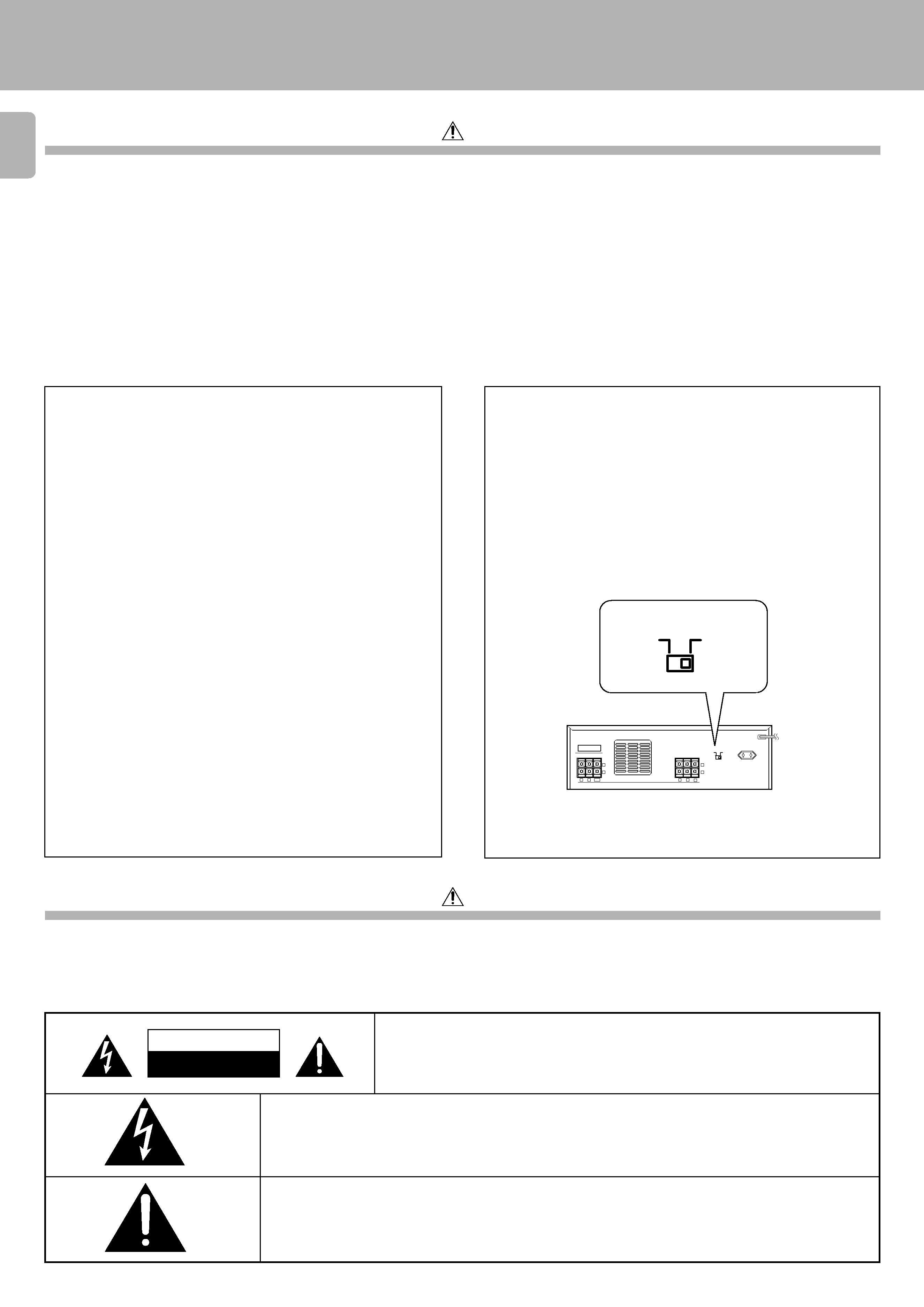
CAUTION
RISK OF ELECTRIC SHOCK
DO NOT OPEN
CAUTION: TO REDUCE THE RISK OF ELECTRIC SHOCK, DO NOT REMOVE COVER
(OR BACK). NO USER-SERVICEABLE PARTS INSIDE, REFER SERVICING TO QUALI-
FIED SERVICE PERSONNEL.
THE LIGHTNING FLASH WITH ARROWHEAD SYMBOL, WITHIN AN EQUILATERAL TRIANGLE, IS IN-
TENDED TO ALERT THE USER TO THE PRESENCE OF UNINSULATED "DANGEROUS VOLTAGE" WITHIN
THE PRODUCT'S ENCLOSURE THAT MAY BE OF SUFFICIENT MAGNITUDE TO CONSTITUTE A RISK OF
ELECTRIC SHOCK TO PERSONS.
THE EXCLAMATION POINT WITHIN AN EQUILATERAL TRIANGLE IS INTENDED TO ALERT THE USER TO
THE PRESENCE OF IMPORTANT OPERATING AND MAINTENANCE (SERVICING) INSTRUCTIONS IN THE
LITERATURE ACCOMPANYING THE APPLIANCE.
WARNING : TO PREVENT FIRE OR ELECTRIC SHOCK, DO NOT EXPOSE
THIS APPLIANCE TO RAIN OR MOISTURE.
Safety precautions
Caution : Read this section carefully to ensure safe operation.
Units are designed for operation as follows.
U.K. ............................................................................................ AC 230 V only
U.S.A. and Canada ................................................................ AC 120 V only
Australia .................................................................................. AC 240 V only
China ............................................................................................... 220 V only
*Other countries ............................... AC 110-120/220-240 V swichable
For the United Kingdom
Factory fitted moulded mains plug
1. The mains plug contains a fuse. For replacement, use only a 13-Amp
ASTA-approved (BS1362) fuse.
2. The fuse cover must be refitted when replacing the fuse in the
moulded plug.
3. Do not cut off the mains plug from this equipment. If the plug fitted
is not suitable for the power points in your home or the cable is too
short to reach a power point, then obtain an appropriate safety
approved extension lead or adapter, or consult your dealer.
If nonetheless the mains plug is cut off, remove the fuse and dispose
of the plug immediately, to avoid a possible shock hazard by
inadvertent
connection to the mains supply.
IMPORTANT: The wires in the mains lead are coloured in accordance
with the following code:
Blue: Neutral
Brown: Live
Do not connect those leads to the earth terminal of a three-pin plug.
*AC voltage selection
The AC voltage selector switch on the rear panel is set to the
voltage that prevails in the area to which the unit is shipped. Before
connecting the power cord to your AC outlet, make sure that the
setting position of this switch matches your line voltage. If not, it
must be set to your voltage in accordance with the following
direction.
Note:
Our warranty does not cover damage caused by excessive line
voltage due to improper setting of the AC voltage selector switch.
AC voltage selector switch
Move switch lever to match your line voltage with a small screw-
driver or other pointed tool.
Before applying power
Caution : Read this section carefully to ensure safe operation.
Introduction
3
M-A300/A100 (En)
Unpack the unit carefully and make sure that all accessories are put aside so they will not be lost. Examine the unit for any possibility of
shipping damage. If your unit is damaged or fails to operate, notify your dealer immediately. If your unit was shipped to you directly, notify
the shipping company without delay. Only the consignee (the person or company receiving the unit) can file a claim against the carrier for
shipping damage. We recommend that you retain the original carton and packing materials for use should you transport or ship the unit in the
future.
Keep this manual handy future reference.
Unpacking
Introduction
Introduction .................................................................................................... 2
Before applying power ...................................................... 2
Safety precautions ............................................................ 2
Special features ............................................................................................ 3
Controls and indicators ................................................................................ 3
System connections ...................................................................................... 4
Terminal connection ................................................................ 4
Connection of M-A300 ............................................................ 5
Connection of M-A100 ............................................................ 6
Contents
Operating instructions ................................................................................. 7
In case of difficulty ....................................................................................... 7
Specifications ........................................................................................ 8
Caution : Read the pages marked
carefully to ensure safe operation.
POWER AMPLIFIER
POWER
-ON OFF
POWER switch
POWER indicator
Controls and indicators
Power amplifier for surround play
This unit is the amplifier designed exclusively for use with the surround speaker, center speaker and subwoofer for the surround system of the
SERIES 21.This unit allows you to enjoy the surround play more effectively.
Special features
AC plug adaptor (1)*
Parallel cord (1)
Accessories
* Use to adapt the plug on the power cord
to the shape of the wall outlet.
(Accessory only for regions where use is
necessary.)
New TRAITR transistor adopted in the final stage
A new TRAITR transistor which features superior temperature tracking characteristics has been adopted in the final stage of the power
amplifier block. This new TRAITR transistor combines a temperature compensation resistor with an emitter resistor and final transistor to
provide ideal temperature compensation characteristics and minimize distortion caused by temperature variations.
4
M-A300/A100 (En)
Notes
Notes
1. Connect all cords firmly. Loose connections may prevent proper sound transmission or produce noise.
2. Be sure to remove the power cord from the AC outlet before plugging or unplugging any connection cords. Plugging / unplugging connection
cords without disconnecting the power cord can cause malfunctions and may damage the unit.
3. Do not connect power cords from components whose power consumption is larger than what is indicated on the AC outlet at the rear of this
unit.
Main unit
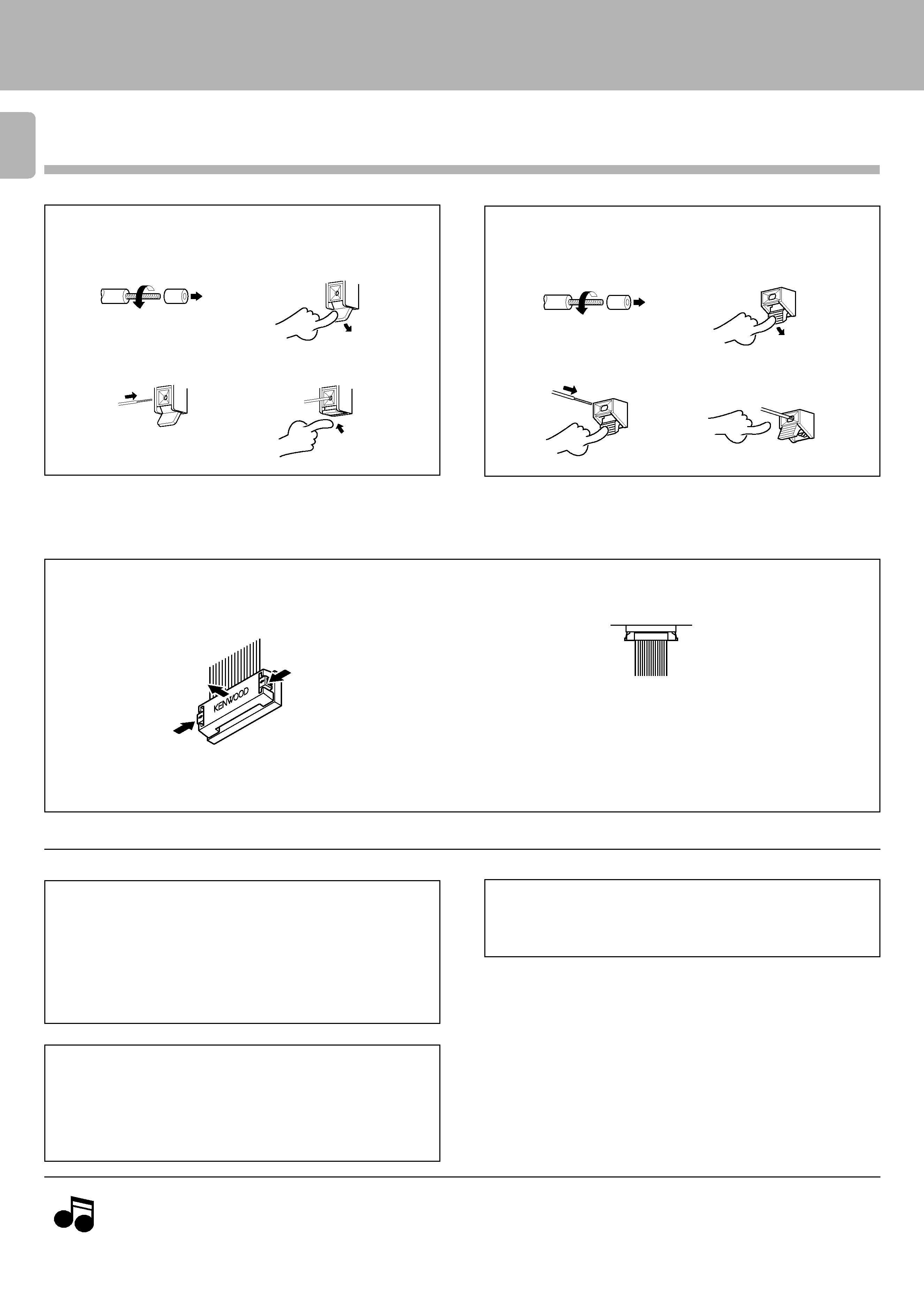
Speaker unit
1 Strip coating.
3 Insert cord.
4 Return lever.
2 Push lever.
Terminal connection
· Never short circuit the + and speaker cords.
· If the left and right speakers are connected inversely or the speaker cords are connected with reversed polarity, the sound will be unnatural with
ambiguous acoustic imaging. Be sure to connect the speakers correctly.
1 Strip coating.
3 Insert cord.
4 Return lever.
2 Push lever.
System connections
UNSWITCHED AC outlet
The power of the component connected to this kind of AC outlet can
be switched ON/OFF regardless of the POWER switch on the main
unit.
AC outlet on the rear panel
· When connecting the parallel cord, insert the plug straight into the
connector until it clicks to lock them securely.
· When disconnecting the parallel cord, push in the two sides of the
plug and pull it straight out.
Connection of parallel cord
Caution regarding placement
(Except for U.S.A. and Canada)
Ventilation fan
The ventilation fan runs during high-power reproduction. To allow for
proper ventilation, do not block the ventilation fan.
To maintain proper ventilation, be sure to leave a space around the
unit (from the largest outer dimensions, including projections) equal
to, or greater than shown below:
Left and right panels: 10 cm, Rear panel: 10 cm
5
M-A300/A100 (En)
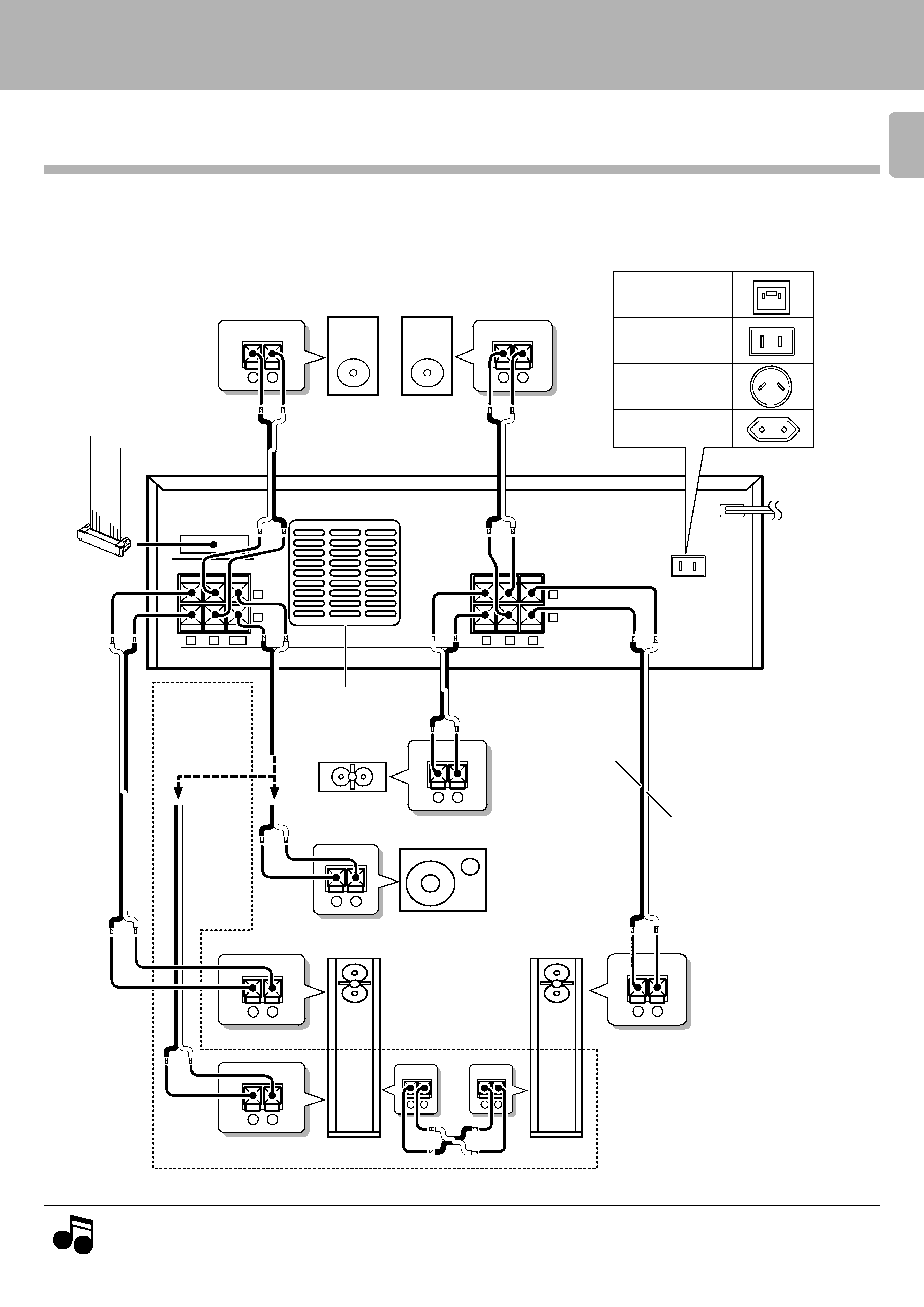
Make connections as shown below. When connecting the related system components, refer also to the instruction manuals
of the related components.
Do not plug in the power lead until all connections are completed.
Connection of M-A300
System connections
Note
Note
The shape of the speakers are variable depending on the system and marketing destination type.
SPEAKERS
(6-16
)
SPEAKERS
(6-16
)
+
-
CONNECT WITH AV
CONTROL CENTER
FRONT
CENTER
R
R
+
-
C
LL
UNSWITCHED
SW
FRONT SURROUND WOOFER
SUB
SURROUND
- +
- +
- +
- +
- +
- +
- +
- +
- +
To AC wall
outlet
Center speaker
Subwoofer
To AV control
center
Right
Left
Front speakers
White lined
See-through
Ventilation fan
U.S.A., Canada
and China
Australia
Other countries
U.K.
AC outlet
Surround speakers
Right
Left
When using
the speaker
system S-F700