
KTC-V500E
TV TUNER
3 page 2 - 5
INSTRUCTION MANUAL
SYNTONISEUR TV
3 page 6 - 9
MODE D'EMPLOI
TV-TUNER
3 Seite 10 - 13
BEDIENUNGSANLEITUNG
TV-TUNER
3 blz 14 - 17
GEBRUIKSAANWIJZING
SINTONIZZATORE TV
3 pagina 18 - 21
ISTRUZIONI PER L'USO
SINTONIZADOR TV
3 página 22 - 25
MANUAL DE INSTRUCCIONES
SINTONIZADOR TV
3 página 26 - 29
MANUAL DE INSTRUÇÕES
© PRINTED IN JAPAN B64-2143-00 (E) (DT)
SI DICHIARA CHE:
Il Sintonizzatore TV Kenwood per auto, modello
KTC-V500E
risponde alle prescrizioni dell'art. 2 comma 1 del D.M. 28 agosto 1995,
n. 548.
Fatto ad Uithoorn il (21 settembre 2001)
Kenwood Electronics Europe B.V. Amsterdamseweg 37 1422 AC
Uithoorn The Netherlands
Installation
2
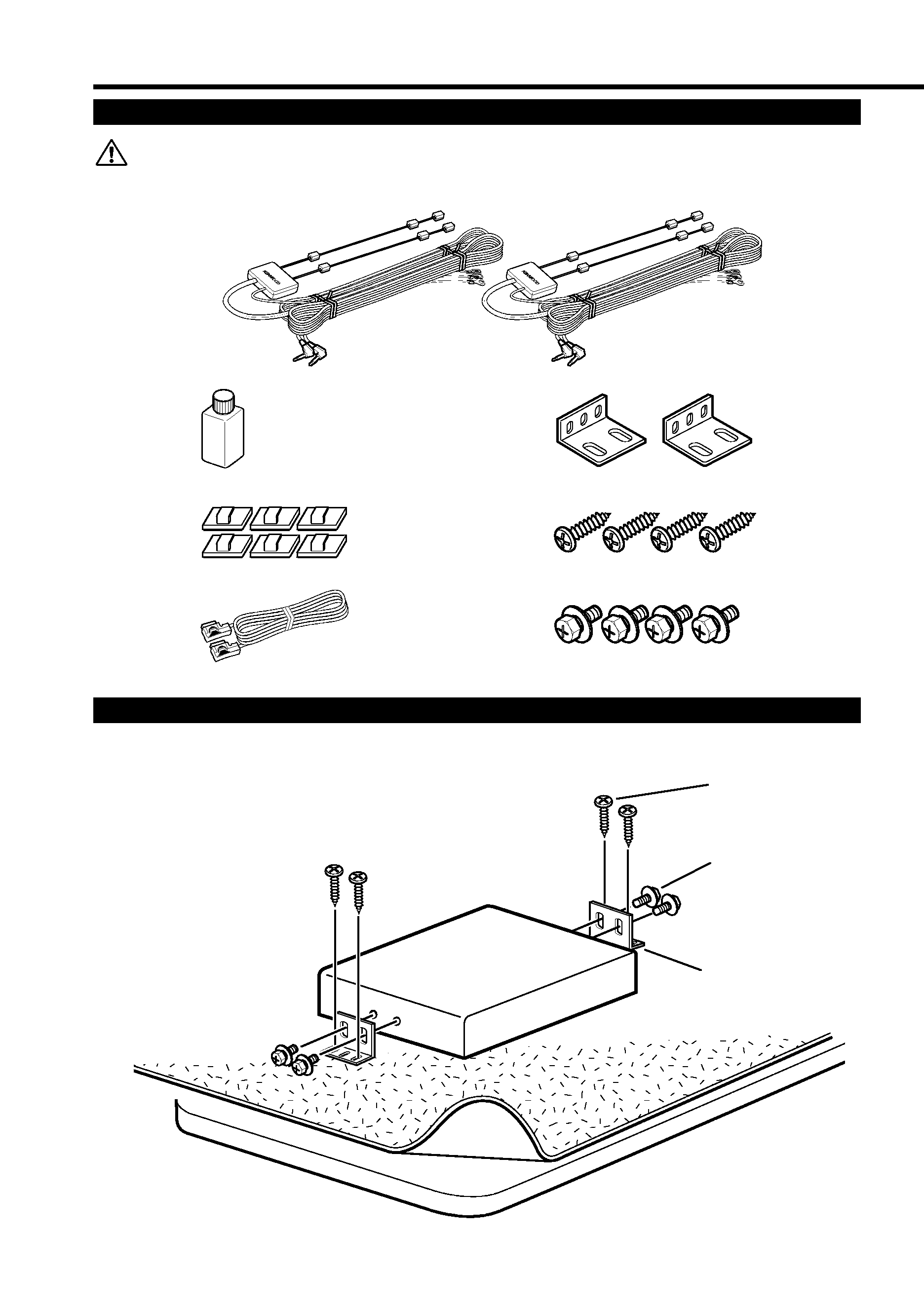
Securing to audio board
(Accessory F)
Installation the TV Tuner Unit
Accessories
G
F
E
A
B
C
(Accessory G)
(Accessory E)
D
The use of any accessories except for those provided might result in damage to the unit.
Make sure only to use the accessories shipped with the unit, as shown above.
3
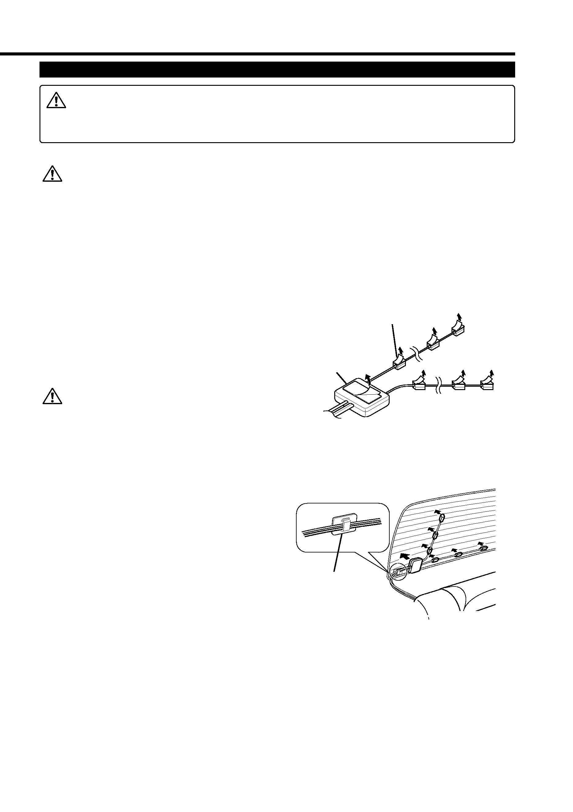
Installing the Antenna Units
· Attach the antenna to the inner glass surface of the rear window using double-sided
tape. Carefully check the installation location as the tape can only be stuck on once.
· If the surface temperature of the glass of the rear window is low, warm it by turning
on the power of the rear defogger.
A cold window glass surface will weaken the adhesive strength of the double-sided
tape.
Also, if installation inside the cabin is performed on a day with high humidity or when
it is raining, the high humidity level will weaken the adhesive strength of the double-
sided tape.
· Do not install the antenna in a location where it may obstruct the field of view during
driving, such as on the windshield.
Check the location where the antenna is to be
attached.Clean off any grease or dirt from the
installation location using the supplied glass
cleaner (Accessory B), clean the area with water
and allow to dry.
Clean the glass thoroughly as failure to
clean the glass can not only weaken the
adhesive strength of the double-sided
tape, but may also cause it to come loose.
Remove the protective strips from the antenna
parts and the back of the antenna unit.
Attach the double-sided tape of the antenna
parts and the antenna unit to the rear windshield
glass. Attach the double-sided tape by firmly
pressing down from the top. Secure cables
using the supplied clampers.
After attaching the antenna with the double-
sided tape, allow it to sit undisturbed for 24
hours. Take care not to apply force to the
antenna or allow it to get wet during this time.
Wire the antenna cable to TV tuner unit.
5
4
3
2
1
Rear seat
Rear window
Bundle cables with the
clamper bar
(Accessory C)
Antenna parts
Antenna unit
Incar antennas have a lower reception sensitivity than antennas intended for outside
mounting. The picture may not appear or may be disturbed if the signal in your area is
weak.
Installation
4
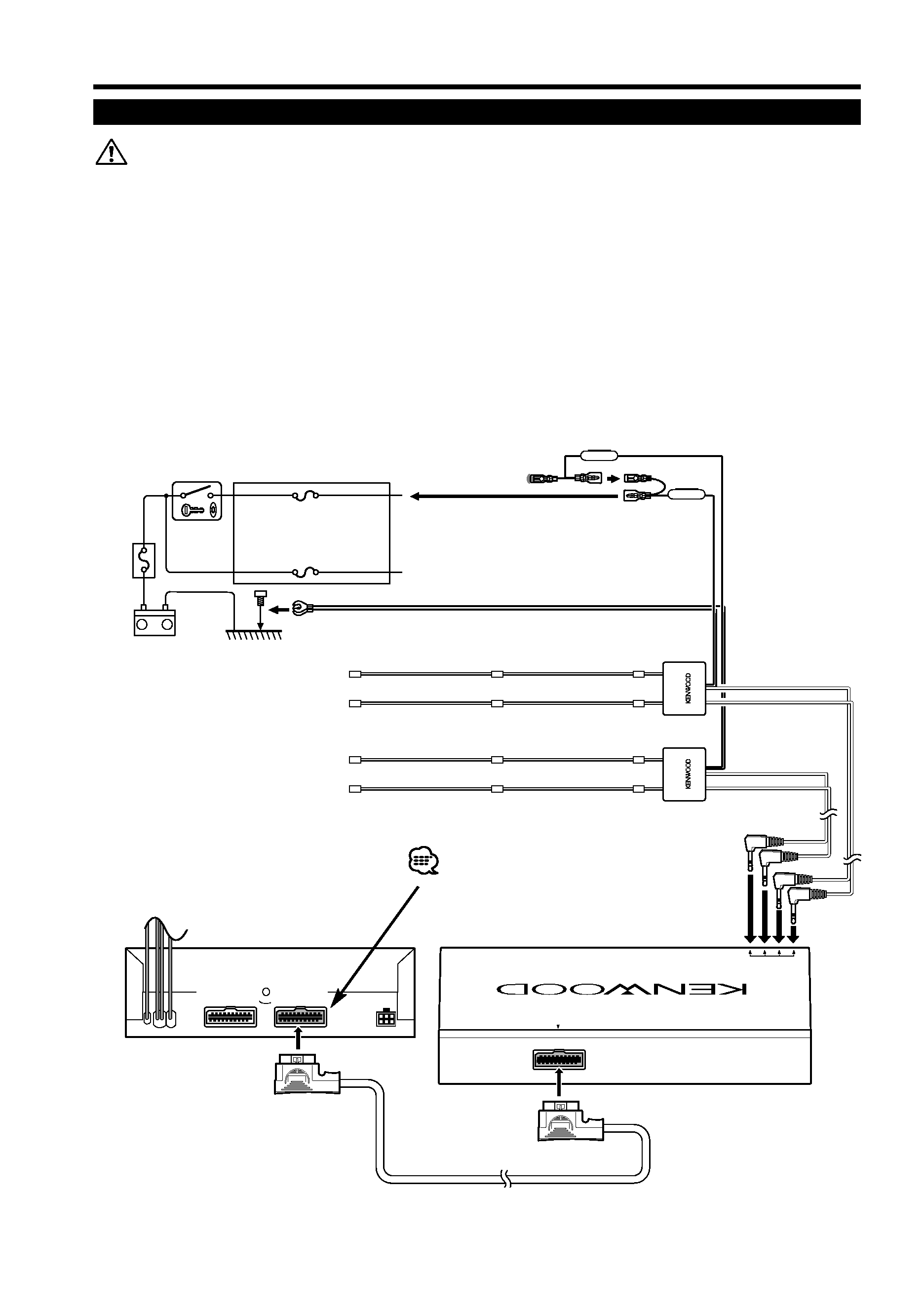
Connection
( 1A )
TVANTENNA
INPUT
TOMONIT
ORUNIT
( 1A )
+
(Accessory D)
Ignition wire (Red)
ª12V
ACC
Ignition key switch
Ground wire (Black)
· (To car chassis)
Battery
Car
fuse
box
(Main
fuse)
·Make sure to ground the unit to a negative 12V DC power supply.
· If your car's ignition does not come with an ACC position, connect the ignition wires
to a power source that can be turned on and off with the ignition key. If you connect
the ignition wire to a power source that receives a constant voltage supply, as with
battery wires, the battery may die.
· If the fuse blows, first make sure that the wires have not caused a short circuit, then
replace the old fuse with one with the same rating.
· After the unit is installed, check whether the brake lamps, blinkers, wipers, etc. on the
car are working properly.
(Accessory A)
(Black)
Remove the protective sheet on
the black connector before the
KTC-V500E is connected.
(White)

5
Specifications subject to change without notice.
TV Tuner Section
Colour system....................................................................................PAL/SECAM
Channel selection system ....................................PLL frequency synthesiser system
Television system ..........................PAL-B/G,PAL-I,SECAM-L,SECAM-D/K, SECAM-B/G
Channel converge
VHF
(PAL-B/G)................................................................................2 - 12 ch/A - H2 ch
(PAL-I)......................................................................................................A - J ch
(SECAM-L) ............................................................................................2 - 10 ch
(SECAM-D/K) ........................................................................................1 - 12 ch
(SECAM-B/G) ........................................................................................2 - 12 ch
UHF ......................................................................................................21 - 69 ch
Demodulation system ............................................................Split carrier system
Antenna input ................................................4-ch diversity (75
/3.5 ø minijack)
General
Operating voltage ..............................................................14.4 V DC (11 to 16 V)
Consumed current ....................................................................................500 mA
Operational temperature range ....................................................10°C to +60°C
Storage temperature range ..........................................................30°C to +85°C
Size ..........................................................................192(W) x 30(H) x 147(D) mm
Mass ............................................................................................................730 g
TV Antenna
Output impedance ................................................................75
/3.5 ø mini plug
Operating voltage ..............................................................14.4 V DC (11 to 16 V)
Consumed current ....................................................................................200 mA
Cable length ....................................................................................................5 m
Size ............................................................................50(W) x 15(H) x 452(D) mm
Mass ......................................................................................................300 g x 2
Specifications