DVD / AV RECEIVER
© 2003-8 PRINTED IN KOREA
B51-5872-00 (K/K) 1679
AC DEC cabinet *
(A29-)
AC DEC crystal *
(B10-)
Pun cover
(A09-1294-08)
In compliance with Federal Regulations, following are repro-
duction of labels on, or inside the product relating to laser
product safety.
KENWOOD Corp. certifies this equipment conforms to DHHS
Regulations No.21 CFR 1040. 10, Chapter 1, subchapter J.
DANGER : Laser radiation when open and interlock defeated.
AVOID DIRECT EXPOSURE TO BEAM.
Caution : No connection of ground line if disassemble
the unit. Please connect the ground line on
rear panel, PCBs, Chassis and some others.
AC DEC cap
(K29-8334-08)
AC DEC button
(K29-8266-08)
AC MLD clamp
(J42-0350-08)
Tuner module *
(W02-)
Conn-spe
(E70-0186-08)
Con phono socket
(E63-1331-08)x3
Phone jack
(E11-0957-08)
AC DEC knob
(K29-8335-08)
AC DEC cap
(K29-8331-08)
Wire-MCRDM *
(E30-)
* Refer to parts list on page 24.
AC DEC cap
(K29-8333-08)
AC DEC button
(K29-8332-08)
AC DEC button
(K29-8330-08)
Con phono socket
(E63-1267-05)x2
Con din socket
(E56-0054-08)
Conn-spe
(E70-0185-08)
DVR-6200
KSW-6200
SERVICE MANUAL
(DVT-6200)
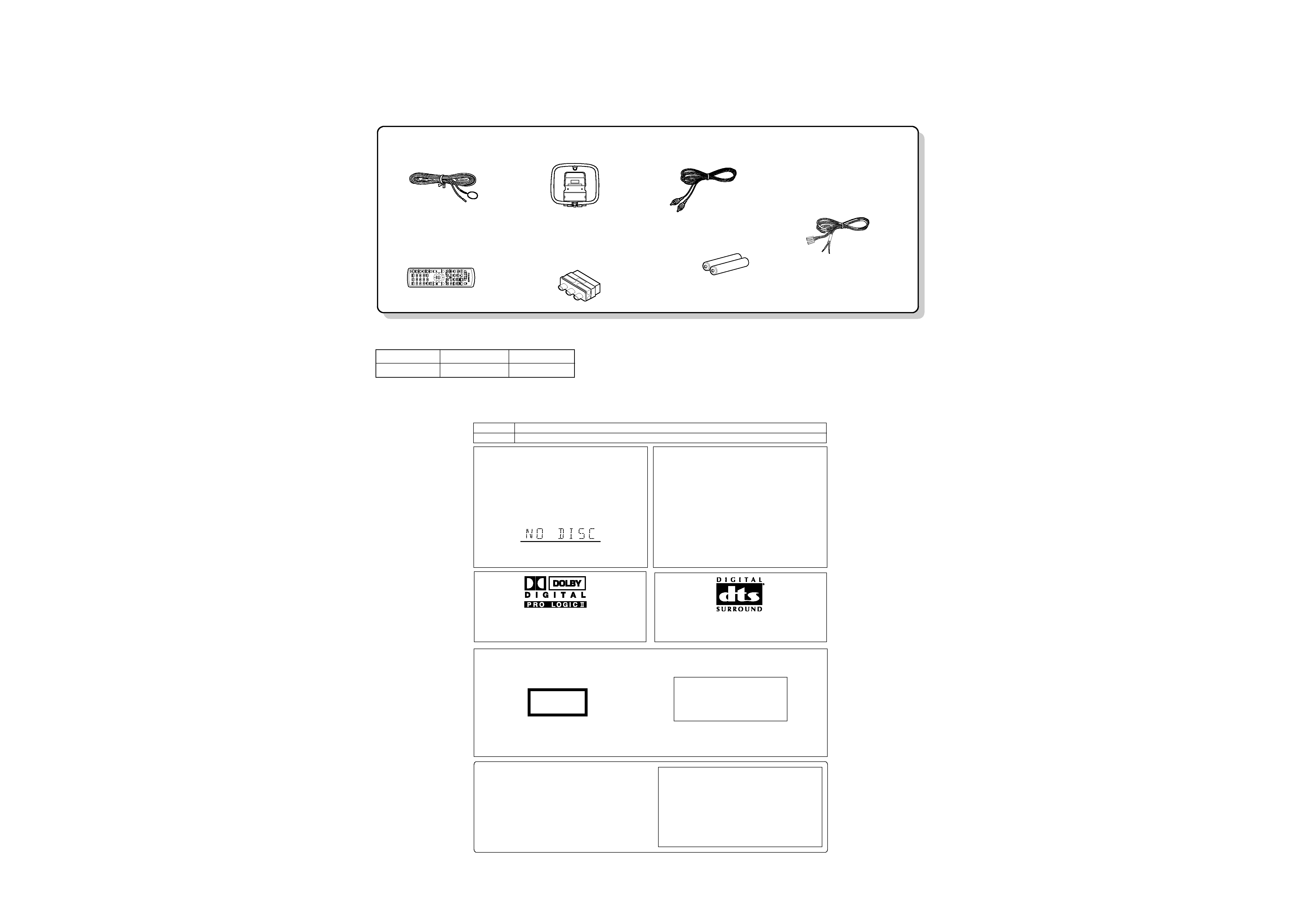
Caution on condensation
Before transporting or moving this unit, carry out the
following operations.
1.Set the POWER ON/OFF switch to theON
without loading a disc.
2. Wait a few seconds and verify that the display
shown appears.
3. Set the POWER ON/OFF switch to OFF.
Note related to transportation and movement
Condensation(of dew) may occur inside the unit when there is agreat
difference in temperature between this unit andthe outside. Thisunit
may not function properly if condensation occurs. In this case, leave
the unit for a few hours and restart the operation after the condensa-
tion has dried up.
Be specially cautious against condensation in the following circum-
stances:
When this unit is carried from one place to another across a large
difference in temperature, when the humidity in the room wher e
this unit is installed increases, etc.
System
Speakers
DVR-6200
KSW-6200 (Left speaker, right speaker, center speaker, surround speakers and subwoofer)
Speaker model names
The marking of products using laser
s
(For countries other than U.S.A. and U.S.-Military)
Inside this laser product, a laser diode classified as Class 2 laser radia-
tion is contained as alerted by the internal caution label shown above. Do
not stare into beam or view directly with optical instruments.
Location: DVD laser pick-up unit cover inside this product
CAUTION
VISIBLE AND INVISIBLE LASER RADIATION
WHEN OPEN. DO NOT STARE INTO THE BEAM OR
VIEW DIRECTLYWITH OPTICAL INSTRUMENTS.
DO NOT PRESSON THIS SURFACE
The marking this product has been classified as Class 1. It
means that there is no danger of hazardous radiation outside
the product.
Location: Back panel
CLASS 1
LASER PRODUCT
Manufactured under license from Dolby Laboratories.
"DOLBY", "Pro Logic" and the double-D symbol are
trademarks of Dolby Laboratories.
"DTS" and "DTS Digital Surround" are trademarks of
Digital Theater Systems, Inc.
Operation to reset
1 Press the MENU key on the remote to enter SETUP
MENU .
2 Select the PREFERENCE, then press the ENTER key.
3 Select DEFAULTS, press the Cursoe right (3) key to
select RESET.
4 Press the numeric keys as shown below.
Press 1 , 3 , 9 , 7 , then press the ENTER key.
When resetting is done according to this method, all set-
tings, including the settings for password and parental level ,
w ill be reset to the factory defaults .
The microprocessormay fall into malfunction (impos-
sibility to operate erroneous display, etc.) w hen the
power cord is unplugged while power is ON or due to
an external factor.
In this case, switch off the power, wait for several sec-
onds, and then switch the power on again.
Return to the factory defaults by resetting the micropro-
cessoris done as shown as follows.
FM indoor antenna (1)
(T90-0882-08): MEX
(T90-0907-08): K
Loop antenna (1)
(T90-0896-08)
Remote control unit (1)
(A70-1647-08): KXM
(A70-1648-08): E
Batteries (R6/AA) (2)
Video cord (1)
(E30-1427-05)
SCART plug adaptor (1)
(Europe only)
(E69-0012-05)
Speaker cords (6)
(E30-5480-08): RD
(E30-5962-08): WH
(E30-7005-05): VT
(E30-5482-08): GN
(E30-5483-08): GY
(E30-5963-08): BL
DVR-6200
2
ACCESSORIES / CAUTIONS
Accessories
Cautions
SYSTEM
MAIN UNIT
SPEAKER
DVT-6200
DVR-6200
KSW-6200
SYSTEM CONFIGURATION
DVR-6200
3
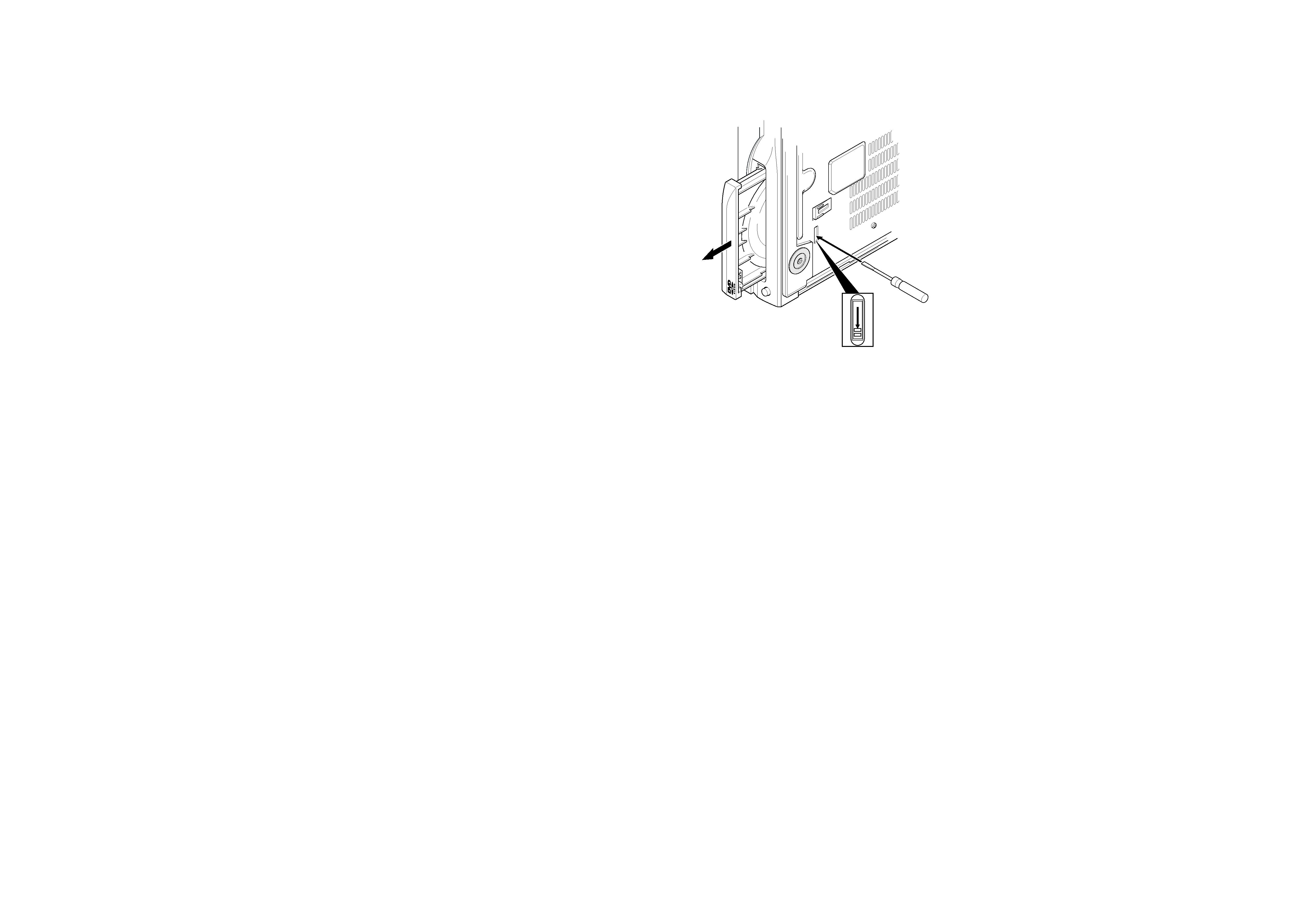
DISASSEMBLY FOR REPAIR
How to open the tray if it does not come out.
1. Insert a flat driver in the drawing through the hole on the loading
chassis bottom and pull the lever down.
2. Pull out the tray frontward by hand when it comes just out.
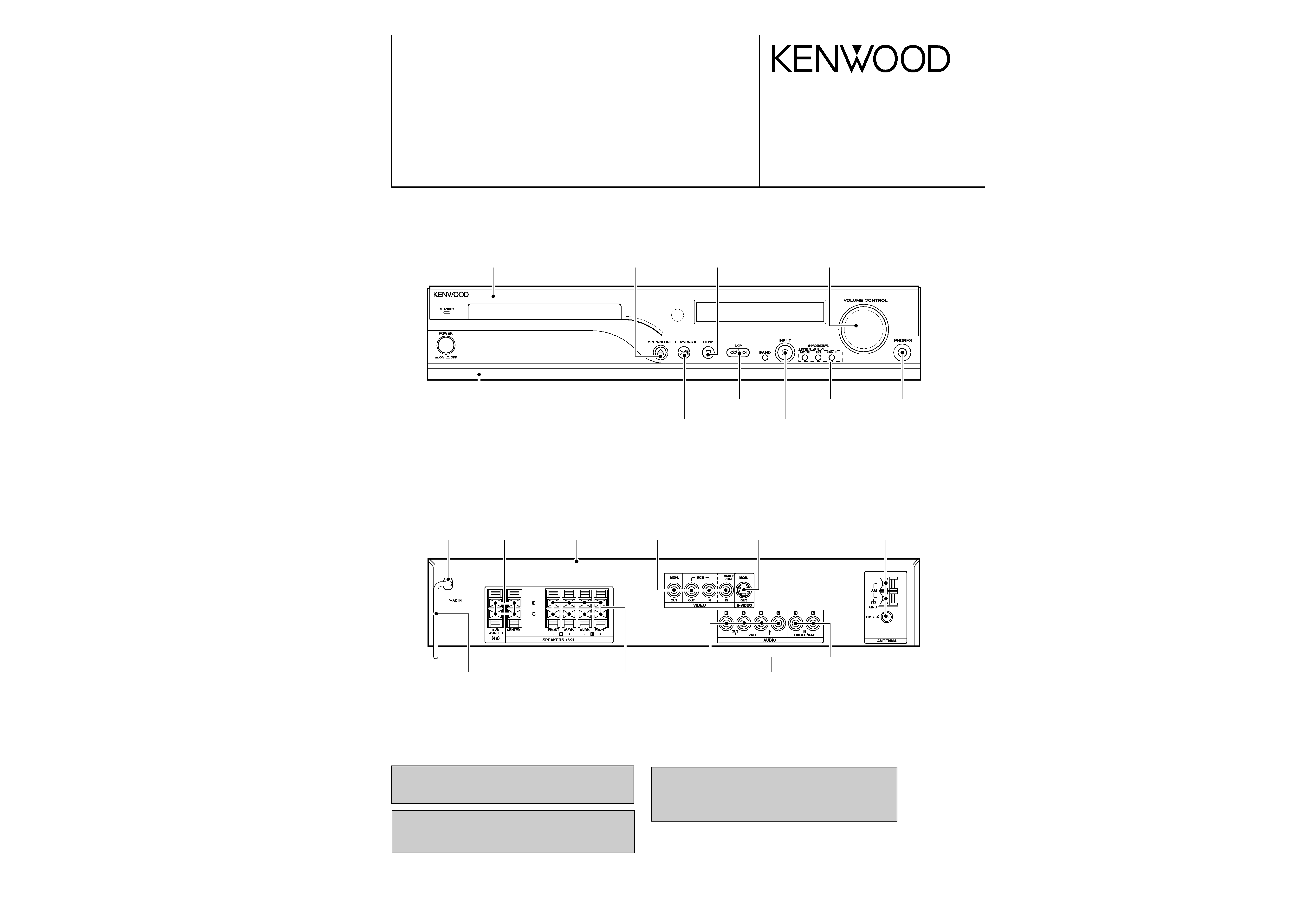
2
ACE
G
I
BD
F
H
J
1
3
5
7
4
6
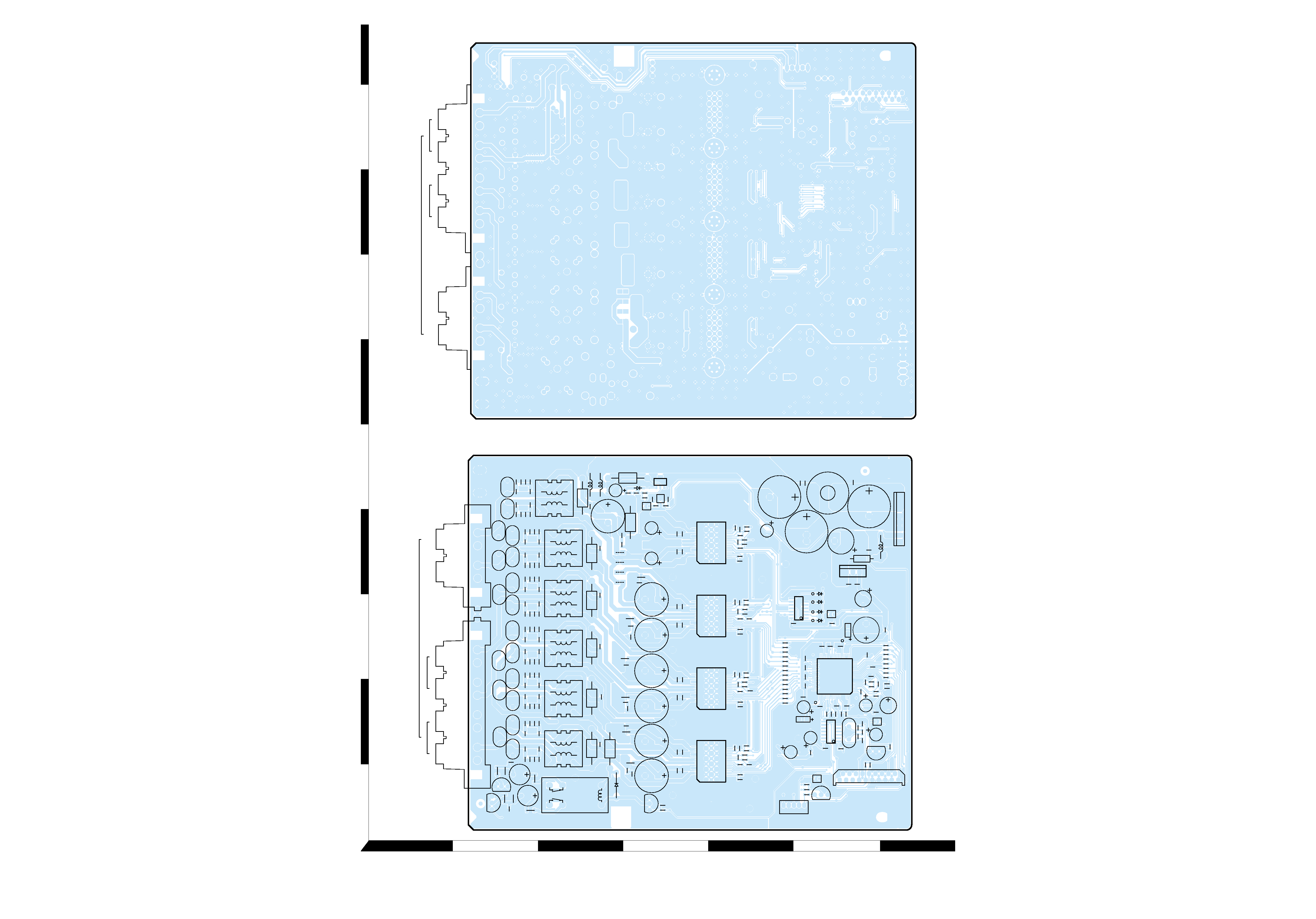
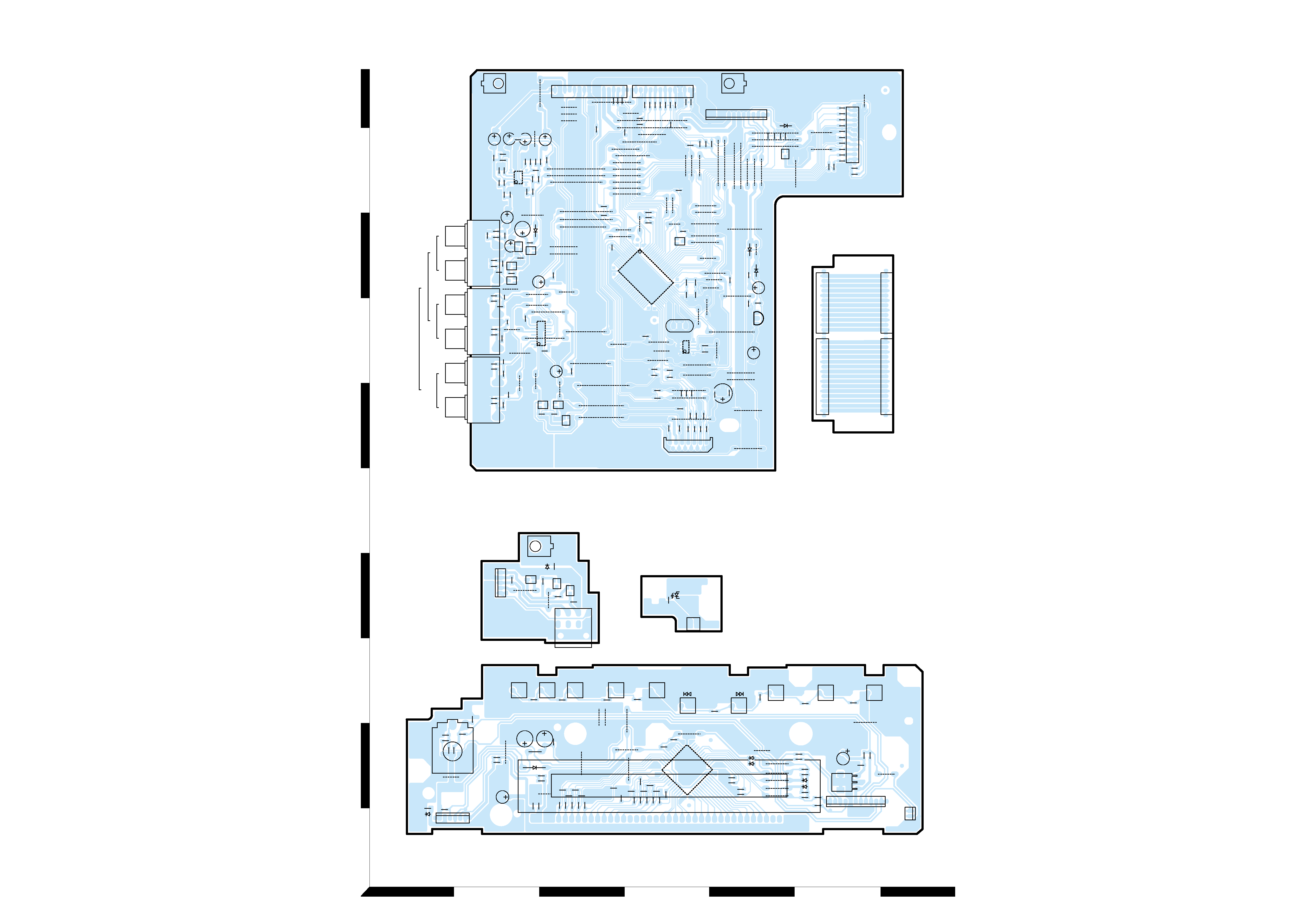
Refer to the schematic diagram for the value of resistors and capacitors.
PC BOARD
5
6
R8
R2
C8
R10
C5
R4
BE
BE
FIT1
R6
R104
R103
R102
R101
C106
C105
C108
C111
C110
R110
C115
C114
C100
C101
C98
C97
C102
C104
C103
R95
R93
R94
R92
R100
R99
R98
R97
R129 C134 C143
C142
C133
C138
C136
C139
C128
C126
C125
C132
C131
C70
C69
C76
R75
R74
R73
R72
C75
C130
C129
C73
C82
C80
C83
C87
C86
C78
C77
C72
C74
R128
R127
R126
R135
R134
R133
R132
R120
R119
R118
R117
R125
R124
R123
R122
R70
R69
R68
R67
R79
R78
R77
R76
R85
R84
R83
R82
L3
L2
C79
R71
C155
C62
R66
R51
R53
R59
EB
EB
C55
C57
R62
R61
C56
C19
C22
C21
C17
FIT2
C16
81
B3
C12
C14
OG
I
L1
C18
C20
C53
TP1
JP1
JP2
R57
C61
C1
R171
C23
C89
C84
R89
R90
C88
R130
R138
R139
C144
C145
R45
R46
R48
R49
R36
R38
R40
R41
R33
R34
R30
R31
C27
R23
R35
R37
R39
R42
R43
R44
R47
R50
R19
R18
R20
C41
C42
C43
C48
C49
C50
B6
C47
R32
C35
R27
C26
C25
R172
C140
R140
R115
C117
R14
R16
R12
C112
C116
R114
R113
C58
R64
C60
R65
R60
R63
C59
R52
R54
R55
R56
JP4
JP3
C71
R81
B2
B1
R58
C54
R109
R108
R107
C7
L5
K1
R106
C107
R96
R131
L7
R121
L6
C3
C149
C146
C94
B14
C92
R91
B11
C4
B10
C63
C93
C90
C95
C91
C96
R137
C141
C113
C109
R105
C9
B4
Y1
R24
1
125
75
51
26
50
100
76
7
14
8
R25
C156
R173
C32
R21
C31
C24
C44
C45
C51
TP2
R29
C26
R22
C29
R28
C37 C38 C39 C40
R112
36
19
118
36
19
118
36
19
118
36
19
118
R111
C137
R136
R86
R88
R80
C81
C85
R87
TP3
17
14
8
TP4 TP5 TP6
C13
B5
C46
B7
C34
C28
C33
C36
C15
R17
RST
G
VCC
C30
C52
C64
C65
C66
C67
C68
C99
C135
C127
B15
R141
C2
C148
B12
R11
R116
C120
B13
C122
BE
R13
C119
C124
C123
C152
C151
C147
C150
C118
C121
L4
R3
R15
C6
SPK1
SPK2
D6
Q8
U4
Q5
Q1
D3
Q3
IC6
IC7
IC3
CN3
CN1
Q2
Q4
D1
D2
D4
D5
CN2
U1
U2
IC2
(SIDE-A)
D-AMP
FRONT
SURR.
L
FRONT
CENTER
WOOFER
SUB
SURR.
R
SPEAERS
Q9
IC5
IC4
Q7
U3
Q6
EB
E
B
E
E
B
1
1
5
19
2
18
B
D-AMP (SIDE-B)
FRONT
SURR.
L
FRONT
CENTER
WOOFER
SUB
SURR.
R
SPEAERS
K
LN
P
R
T
MO
Q
S
2
1
3
5
7
4
6
Refer to the schematic diagram for the value of resistors and capacitors.
PC BOARD
8
7
C728
R744
C726
1
1
2
3
37
38
39
6
J702
R729
C710
R728
HP1
J715
R731
C714
G701
R703
13
R705
C707
C706
R702
R701
J721
R741
R743
R740
R739
R736
R735
R734
R737
40
52
1
C708
R709
R721
R717
R716
R715
R714
J710
R712
J707
J708
J709
J705
J741
R711
C732
C731
C730
C729
R713
R710
C703
J711
11
I
G
+B
1
R719
R718
J719
C711
R708
12
R707
R720
13
14
26
27
39
J722
J703
R723
R722
R742
R725
DIMMER
ACTIVE
EQ.
LISTEN
MODE
INPUT
BAND
SKIP
STOP
PLAY/PAUSE
POEN/CLOSE
R724
V706
R704
R727
R726
C709
J723
C704
J718
J720
C713
R732
C727
51
J716
C702
C701
C725
C724
C723
C722
C721
C720
C719
R738
C718
C717
C716
C715
C705
J701
J706
R706
21
J740
EB
EB
EB
FRONT
HEADPHONE
STAND-BY LED
PHONES
D703
P703
S711
D702
S710
S709
S708
S707
S705
I701
D707
D708
FL701
D705
D706
P704
RM701
N701
S701
S702
S704
S703
D701
P701
N702
HP51
Q700
Q701
Q702
D704
D500
D502
P501
I504
I501
I500
I502
P505
N501
N402
N503
N504
D503
D501
I503
P504
P502
P503
K501
K502
K503
Q507
Q508
Q511
Q510
Q509
Q502
Q501
Q503
Q504
J15
BE
BE
EB
J17
J4
J2
J96
J98
J3
J8
J6
J7
J9
J5
J16
J89
J37
J22
J21
J18
J75
J38
J39
J32
J12
J10
J84
J23
J68
J57
J35
J34
J94
J78
J33
J31
J36
J40
J54
J69
J95
J46
J41
J64
J26
J19
J97
J29
J62
J63
J73
J88
J60
J76
J61
J27
J28
J30
J58
J70
J72
J71
J74
J90
J83
J66
J65
J67
J77
J56
J55
J53
J91
J52
J51
J47
J48
J49
J50
J1
J44
J42
J59
J45
J82
J81
J20
J14
J87
J43
J11
J86
J80
J79
J85
J24
J25
J13
R529
R530
R531
R532
R521
R527
R636
R526
R627
R628
R528
C538
R543
R635
R637
R631
R630
R629
R509
R510
R511
R512
R513
R514
R518
R515
R516
R517
R525
R523
R524
R626
GND2
R625
R506
R507
R536
R537
R535
R534
R533
R538
R539
R540
R541
R542
R520
R522
1
11
12
1
15
1
12
1
15
1
1
12
1
1
12
15
R519
R569
R553
R604
C511
R555
R556
C512
R557
C513
14
85
C507
R548
C506
C515
R559
R550
C523
R581
R578
R575
R577
R576
R579
R582
R580
L503
R567
R558
R570
R560
R551
C528
C525
C522
L500
R601
R602
C530
C529
C524
C508
C504
C517
C516
C510
GND1
C518
C521
C514
C532
C531
C526
C527
R552
C509
R549
R547
R546
C505
R544
R545
R568
R554
R501
R500
R598
R623
C500
OG
I
R508
C537
R624
R621
R622
R600
R599
R619
R620
R634
R583
R595
R596
R597
R593
R591
R590
R633
R584
R594
R592
R632
R589
1
13
12
2
C534
C533
C503
C501
L502
R504
1
25 24
40
41
64 65
80
1
16
9
18
4
85
X500
R505
LR
IN
LR
IN
LR
OUT
VCR
AUDIO
SAT/CABLE
MAIN
LINK
BE
EB
EB
BE
EB
EB