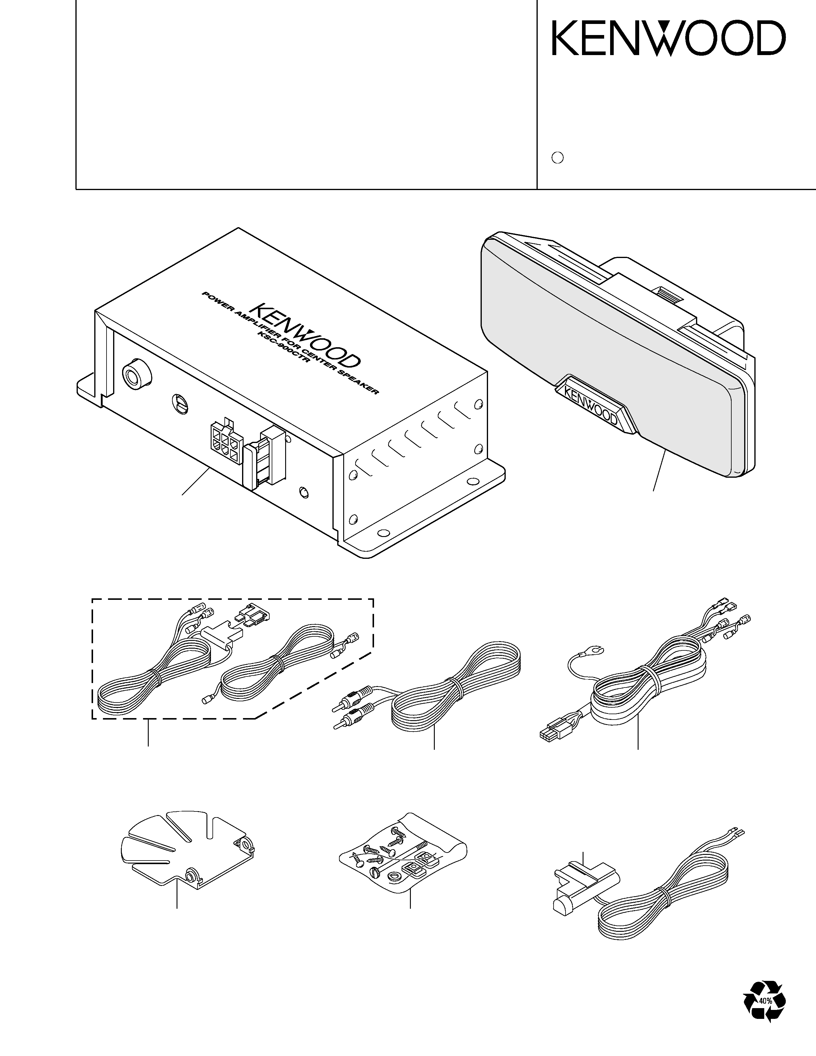
KSC-900CTR
2000-12 PRINTED IN JAPAN
B51-7709-00 (4) 3397
ACTIVE CENTER SPEAKER
SERVICE MANUAL
C
BRACKET
(J19-4158-08)
BRACKET
(J19-4159-08)
CORD WITH PINJACK
(E30-5904-08)
SCREW SET
(N99-2127-08)
CORD WITH CONNECTOR
(E30-5905-08)
DC CORD ASSY
(E30-5923-08)
AMPLIFIER
(W03-5036-08)
PLASTIC CABINET ASSY
(A02-2556-08) (W) (M)
KSC-900CTR
2
1
2
1
2
1
2
1u50
+
C101
22K
R104
+
22K
R106
C105
1u50
1.8K
R102
3300P
C124
3
2
1
R107 10K
C103 100P
22K
R101
10K
R103
8200P
C106
8200P
C107
56K
R110
5
6
8
4
7
56K
R108
1u50
+
C123
20K
VR1
1K
R109
1u50
C104
+
9
7
10
17
12
11
13
14
16
15
1
3
2
8
4
6
5
FIL
GND
GND
GND
IN
SBY
NC
NC
10K
R1
13
10u35
+
C1
16
R112 5.6K
100u16
C
111
+
R111 68
+
47u16
C1
10
22K
R116
220u10
+
C112
0.1
C122
1
R122
1000P
C1
18
1000u16
C1
14
+
0.1
C1
13
C120
220u10
+
C121
R121
0.1
1
C1
19
100u16
+
5.6K
R124
68
R123
R125
33K
47K
R120
27K
R1
15
100P
C1
17
47K
R801
10u35
C801
+
56K
R802
47u16
C804
+
1K
R803
47u16
+
C805
R804 3.3K
R812 3.3K
100u16
+
C806
560
R805
33K
R806
68K
R809
3.3K
R807
82
R810
1.5K
R808
0.01
C807
15K
R811
1000P
C808
L801
F801
3A
1
2
3
4
5
6
SP+
SP-
BATT
GND
REM
CN2
CN3
PJ1
IC2
IC2
Q2
D802
D804
Q5
Q3
Q4
Q6
D803
D801
CN1
IC1
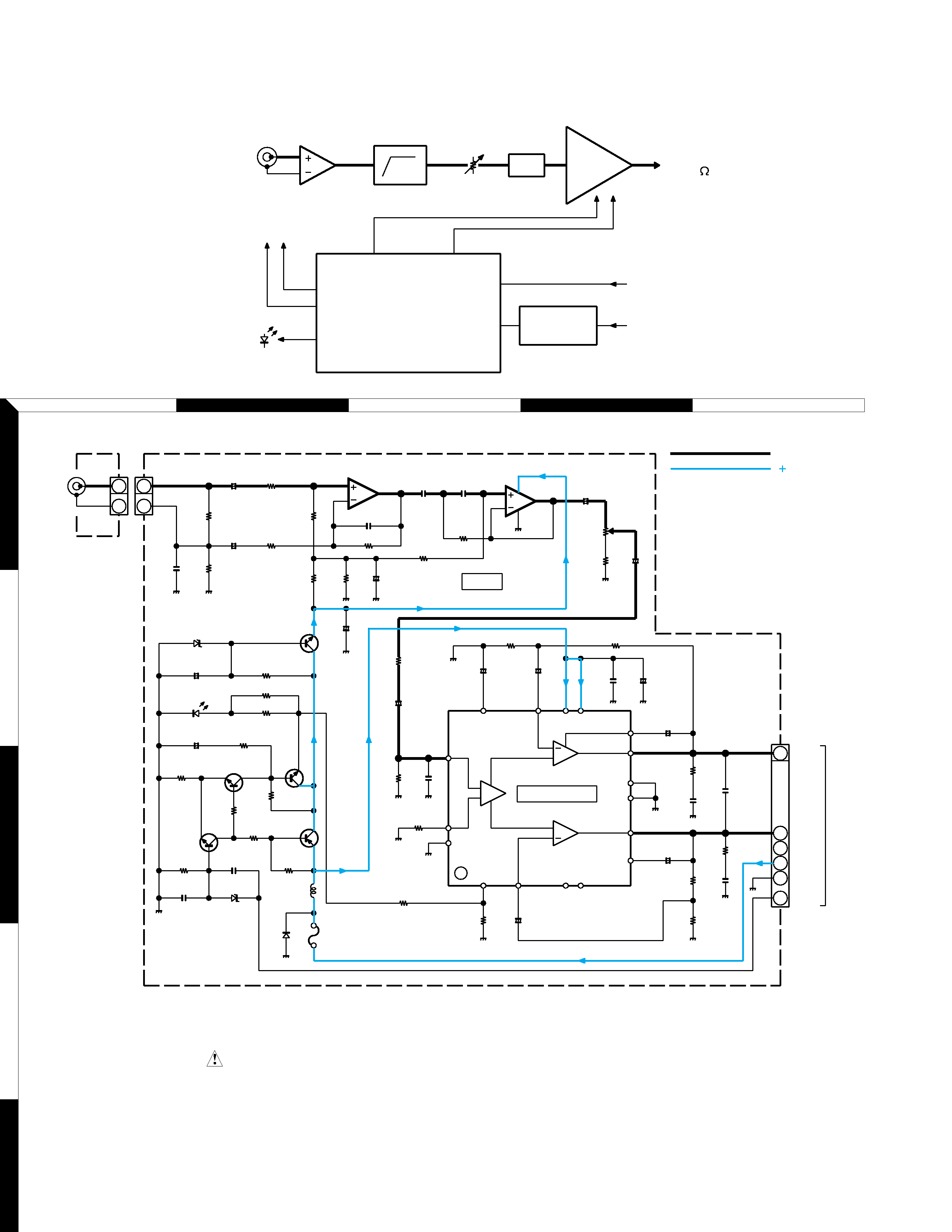
: TA8225H
IC2
: NJM4558L
Q2,3,5,6 : 2SC2785
Q4
: 2SB1237
D802
: MTZJ10B
D803
: MTZJ6.8B
D804
: SEL4114R
SIGNAL LINE
D801
RM10Z
:
H.P.F.
POWER AMP
IC1
400Hz -12dB/oct
REGULATED
BIAS
STND-BY
CONTROL
VCC
REM
BATT
SPEAKER
OUT 4
AMP
IC2
H.P.F
ATT
POWER SUPPLY SECTION
LED
CONTROL
REMOTE
POWER
AMP
IC1
Q6
Q2-5
INPUT
VOLUME
B
C
A
D
E
2
4
3
5
1
CAUTION: For continued safety, replace safety critical components only
with manufacturer's recommended parts (refor to parts list).
Indicates safety critical components. To reduce the risk of electric shock,
leakagecurrent or resistance measurements shall be carried out (exposed
parts are acceptably insulated from the supply circuit) before the appliance
is returned to tha customer.
BLOCK /SCHEMATIC DIAGRAM
B LINE
KSC-900CTR
3
A
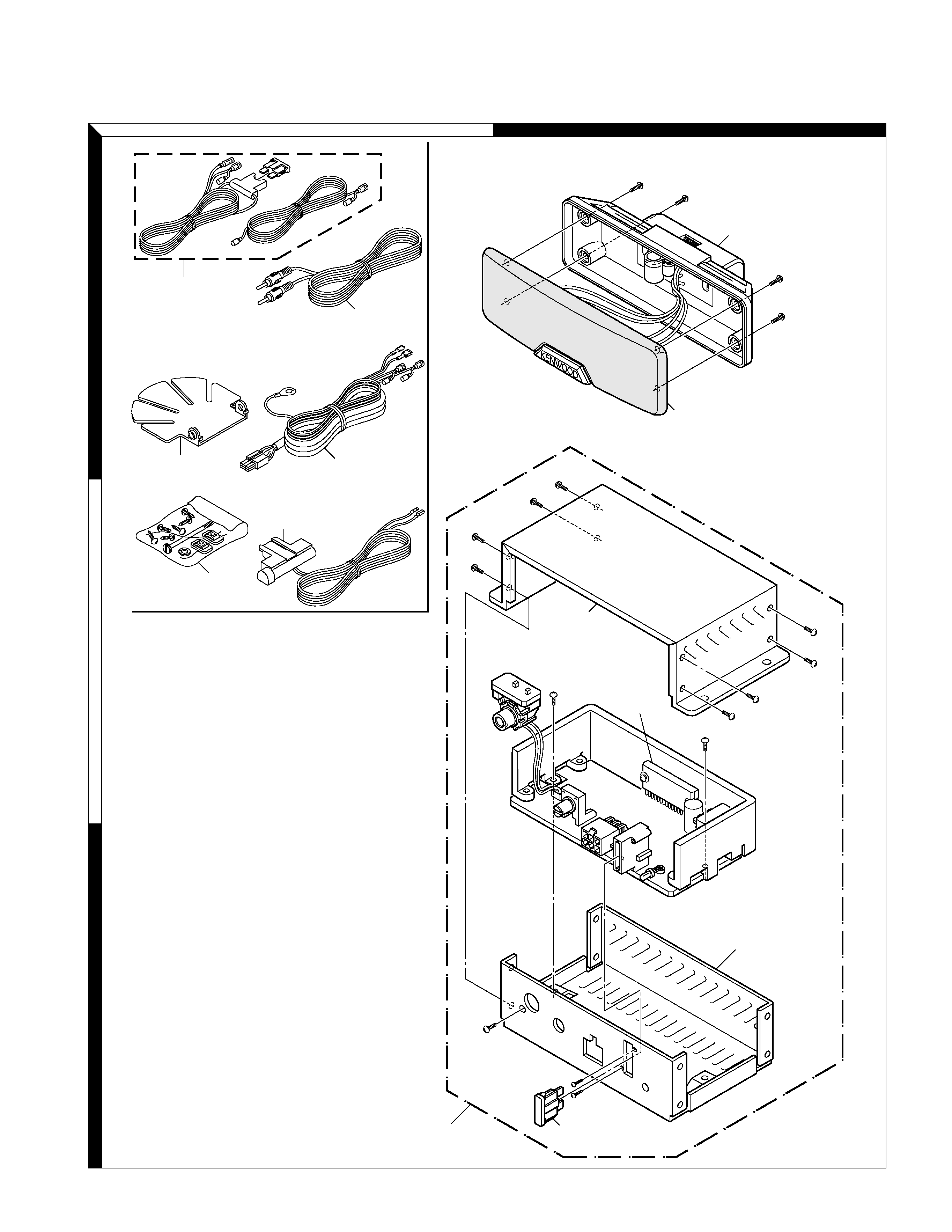
Parts with the exploded numbers larger than 700 are not supplied.
B
3
2
1
EXPLODED VIEW/PARTS LIST
A
B
C
D
E
F
G
H
J
3x10 (BLK)
3x8 (BLK)
2x8 (BLK)
3x8
3x12
3x6 (BLK)
WASHER
WASHER
WASHER
A
A
A
A
B
B
B
B
B
F
F
B
C
C
B
B
B
: N82-3010-45
: N50-3008-45
: N82-2008-45
: N09-3762-08
: N09-3763-08
: N50-3006-45
: N16-0030-46
: N15-1030-08
: N19-0458-08
BRACKET
(J19-4158-08)
BRACKET
(J19-4159-08)
CORD WITH PINJACK
(E30-5904-08)
PLASTIC CABINET
(A02-2547-08)
CASE
(A02-2557-08)
CASE
(A02-2558-08)
AMPLIFIER
(W03-5036-08)
IC
(TA8225H)
PLASTIC CABINET ASSY
(A02-2556-08) (W) (M)
SCREW SET
(N99-2127-08)
CORD WITH CONNECTOR
(E30-5905-08)
DC CORD ASSY
(E30-5923-08)
FUSE
3A
WARRANTY CARD
: B46-0100-50
INSTRUCTION MANUAL
: B61-1090-00
ITEM CARTON CASE (M)
: H51-1626-08
ITEM CARTON CASE (W)
: H51-1627-08
POLYSTYRENE FIXTURE
: H10-8195-08

KSC-900CTR
[AMPLIFIER]
Audio
Max. Power Output .................................................................................................................................. 35W
Rated Power Output ................................................................................................................................ 20W
Frequency Response ........................................................................................................... 400 ~ 50,000Hz
Signal to Noise Ratio .............................................................................................................................. 85dB
Total Harmonic Distortion ..................................................................................................................
0.15%
Sensitivity ................................................................................................ Vol Max. 200mV / Vol Min. 5000mV
Power Supply
Operating Voltage (-GND) ..................................................................................................................... 14.4V
Current Consumption (Max.) ................................................................................................................... 2.4A
[SPEAKER]
Electrical
Nominal Impedance .................................................................................................................................... 4
Power Handling
Peak Input Power .............................................................................................................................. 60W
Maximum Input Power ....................................................................................................................... 35W
Rated Input Power ............................................................................................................................. 20W
Frequency Response ............................................................................................................ 300 ~ 70,000Hz
Design
System .................................................................................................................................. 2Way 2Speaker
Enclosure ............................................................................................................................................. Sealed
Mounted Speaker
[mm]
[in.]
MATERIAL
Woofer
Diaphragm
70
×40
3
×1.6
Pulp Cone (Black)
Surround
Cloth
Magnet
15 - t4×2
Neodymium
Tweeter
Diaphragm
16
3/4
Hypernyl Dome Type (Gray)
Magnet
15 - t2
Neodymium
Dimension
SP [mm]
AMP [mm]
Width
140
156
Height
46.3
40
Depth
118.5 (with bracket)
77
Weight
Net Weight (PC.)
180g (with bracket)
362g
Gross Weight
1.3kg
Weight of Magnet
11g
5.5
×2 (wo) 2.75g (tw)
SPECIFICATIONS
KENWOOD follows a policy of continuous advancements in development. For this reason specifications may be changed without notice.
KENWOOD CORPORATION
14-6, Dogenzaka 1-chome, Shibuya-ku, Tokyo, 150-8501 Japan