AV SURROUND RECEIVER
KRF-V8010D/V8010DW
SERVICE MANUAL
© 1998-8/B51-5464-00 (K/K) 1751
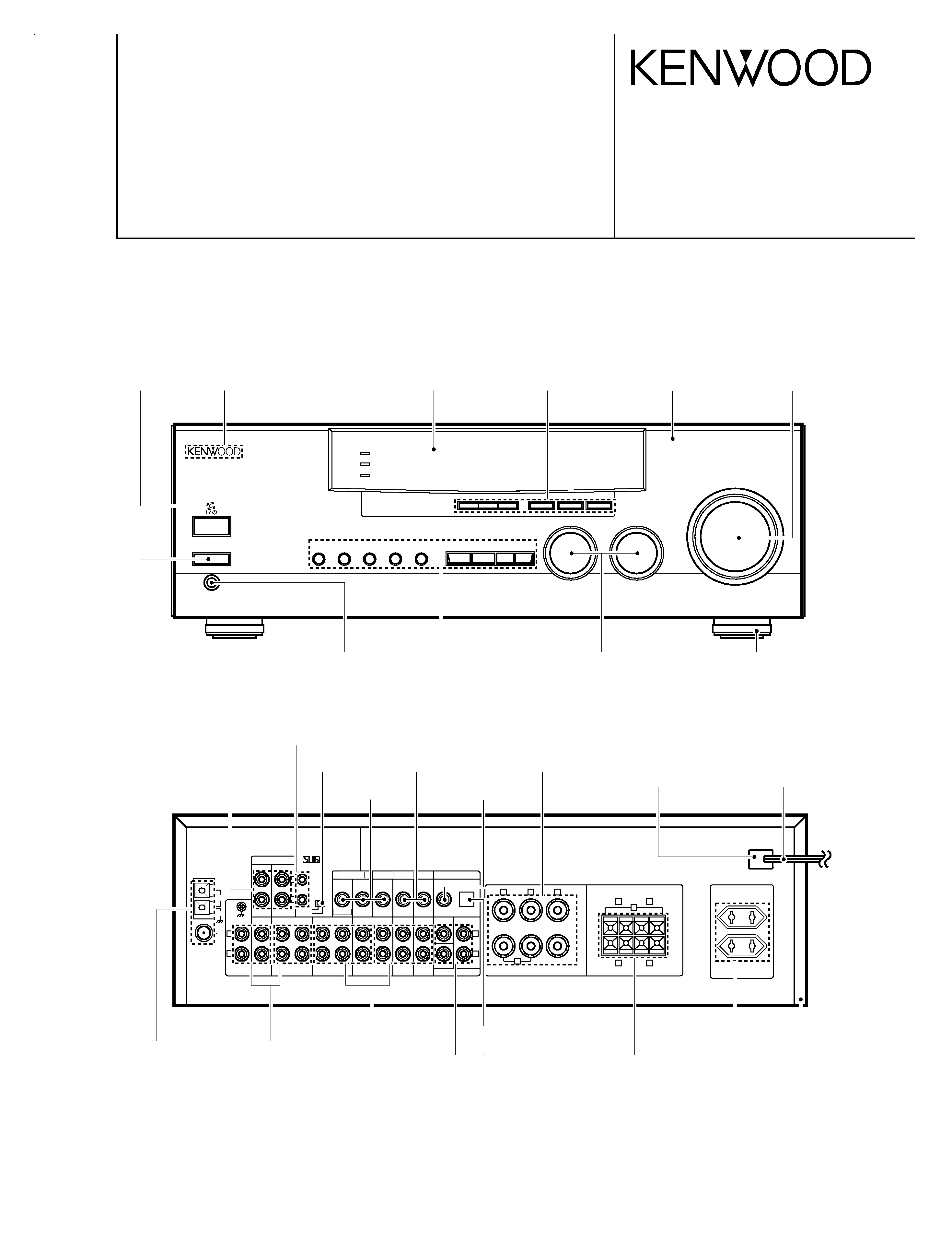
A
SPEAKERS
B
BASS BOOST
MONITOR
SOURCE
DIRECT
MULTI CONTROL
INPUT SELECTOR
VOLUME CONTROL
DOWN
UP
STANDBY
AV SURROUND RECEIVER
ON / STANDBY
PHONES
- ON OFF
POWER
PTY
TA/NEWS
DISPLAY
BAND
AUTO
MEMORY
INPUT MODE LISTEN MODE SOUND
SETUP
DOLBY DIGITAL
DVD 6ch INPUT
CLIP INDICATER
CENTER SPEAKER
FRONT SPEAKERS
FM
75
GND
AM
ANTENNA
SYSTEM CONTROL
REC OUT
PHONO
DVD 6CH. INPUT
CD
MD / TAPE
VIDEO 1
VIDEO 1
VIDEO 2
VIDEO 3
VIDEO 1
VIDEO 2
DVD 6CH.
VIDEO 3
DVD 6CH.
VIDEO 2
DOLBY DIGITAL / PCM IN
VIDEO 3
SUBWOOFER
SUBWOOFER
SURROUND
SURROUND
SURROUND
SPEAKERS
FRONT SPEAKERS
PRE
OUT
MONITOR
PLAY IN
REC OUT
PLAY IN REC OUT
PLAY IN
PLAY IN
PLAY IN
CENTER
CENTER
SL16
XS8
L
R
+
+
+
+
-
-
-
-
+
+
--
R
A
L
C
L
L
R
L
R
R
L
R
B
MONITOR
VIDEO IN
VIDEO OUT
Indicator
(B12-0341-04)
KENWOOD badge
(B43-0302-04)
Metallic cabinet *
(A01-)
AC outlet *
(E03-)
Phono jack x 2
(E63-0046-15)
Phono jack x 2
(E63-0047-15)
Lock terminal board
(E20-0321-05)
Power cord bushing
(J42-0083-05)
AC power cord *
(E30-)
Knob
(K27-2275-04)
Phone jack(3P)
(E11-0127-05)
Foot x4
(J02-1168-03)
Optical receiving module
(W02-1181-05)
Lock terminal board
(E70-0047-05)
Phono jack
(E63-0094-05)
Phono jack
(E63-0199-05)
Slide switch
(S62-0034-05)
Phono jack
(E63-0114-05)
Front glass
(B10-3428-12)
Knob
(K29-7311-03)
Panel *
(A60-)
Knob
(K29-7312-04)
Miniature phone jack(2P)
(E11-0188-05)
Knob
(K29-7313-04)
Knob *
(K29-7371-02)
(E,T,Q,X type)
This manual is available for repair in the Europe, England, Australia and Russia markets.
Please refer to the original manual (B51-5419-00) if need the information in the USA and Canada
and other markets.
* Refer to parts list on page 31 .
Phono jack
(E63-0093-05)
Screw terminal board
(E70-0100-05)
Phono jack
(E63-0114-05)
KRF-V8010D(K)COVER1,1( 98.12.1017:50 y[W 2
Resetting the Microcomputer
If the microcomputer may malfunction (unit cannot be operated,
or shows an erroneous display) if the power cord is unplugged
while the power is ON, or due to some other external factor. If this
happens, execute the following procedure to reset the micro-
computer and return the unit to its normal operating condition.
Please note that resetting the microcomputer will clear the contents
of the memory and returns the unit to the state it was in when it left the
factory.
With the power cord plugged in, turn the POWER key
OFF. Then, while holding down the ON/STANDBY key,
press POWER.
·
FM
(T90-0836-05)
(A70-1252-05)
Battery cover (A09-0366-08)
indoor antenna (1)
Loop antenna stand (1)
Remote control unit (1)
Batteries (R03/AAA) (4)
AM loop antenna (1) (T90-0833-05)
KRF-V8010D/V8010DW
2
CONTENTS / ACCESSORIES / CAUTIONS
CONTENTS / ACCESSORIES / CAUTIONS.............2
CONTROLS ...............................................................3
DISASSEMBLY FOR REPAIR...................................5
BLOCK DIAGRAM .....................................................6
CIRCUIT DESCRIPTION ...........................................7
ADJUSTMENT ........................................................ 10
PARTS DESCRIPTIONS .........................................11
PC BOARD ..............................................................12
SCHEMATIC DIAGRAM ..........................................17
EXPLODED VIEW ...................................................30
PARTS LIST.............................................................31
SPECIFICATIONS ...................................................40
Contents
Accessories
Cautions
Please refer to KRF-V5010 (B51-5425-00) and KRF-V7510D (B51-5419-00) service manuals if
need the information on circuit description.
KRF-V8010D(K)COVER1,1( 98.12.1017:50 y[W 3
***** **
*;
FM
AM
kHz
MHz
3 STEREO
B
S.DIRECT
A
SP
TI.VOL
MUTE
RDS EON PTY
TP TA NEWS
DOWNMIX
MONITOR
PRO LOGIC
TUNED
MEMO.
AUTO
ST.
S
SW
C
RS
R
LS
L
DIGITAL
1
2
!
6
5
4
3
9 0
7 8
@
¢
£
*
&
^
#
AUTO SOUND
Z$ %
A
SPEAKERS
B
BASS BOOST
MONITOR
SOURCE
DIRECT
MULTI CONTROL
INPUT SELECTOR
VOLUME CONTROL
DOWN
UP
STANDBY
AV SURROUND RECEIVER
ON / STANDBY
PHONES
- ON OFF
POWER
PTY
TA/NEWS
DISPLAY
BAND
AUTO
MEMORY
INPUT MODE LISTEN MODE SOUND
SETUP
( ) ¡ TM
DOLBY DIGITAL
DVD 6ch INPUT
CLIP INDICATER
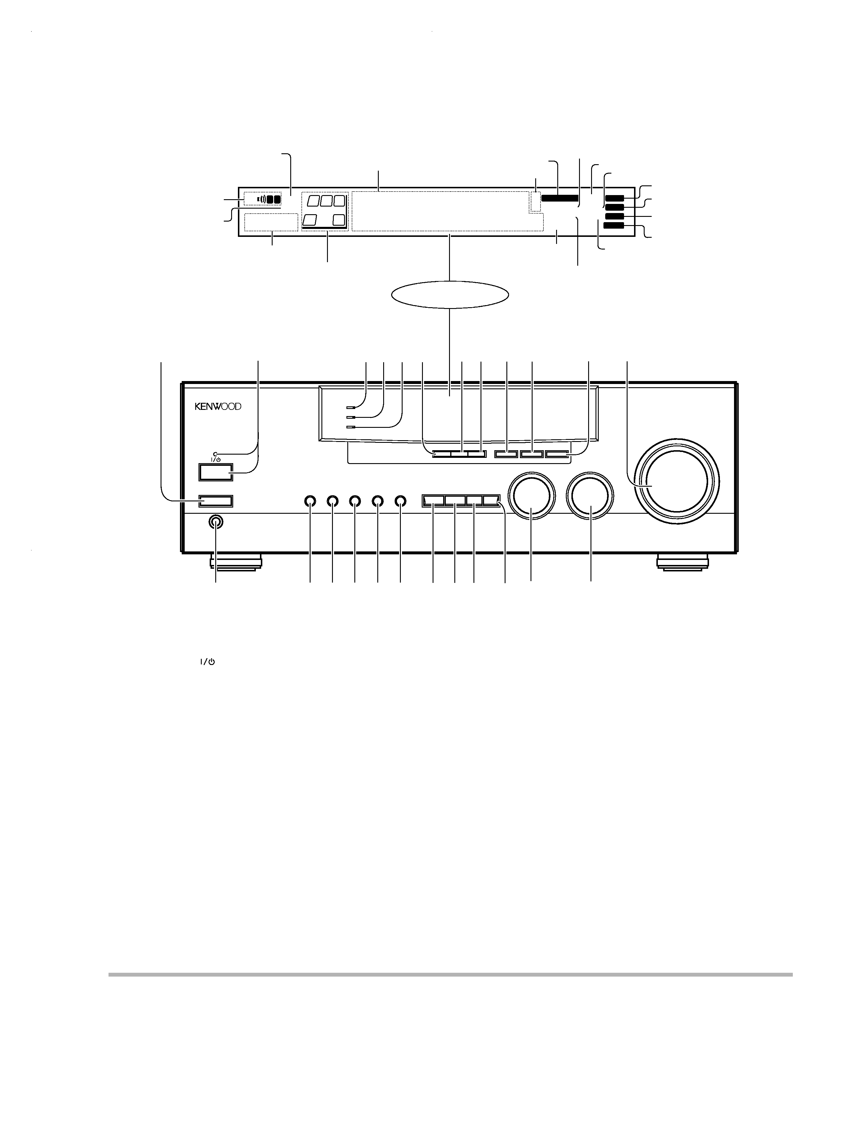
Display
Speaker selection indicators
Output channel indicators
Band indicators
AUTO indicator
MEMO. indicator
ST. indicator
TUNED indicator
3 STEREO indicator
STEREO indicator
About the STANDBY indicator
This unit has a STANDBY indicator. When the STANDBY indicator is lit, the unit consumes a small amount of power to preserve the memory. This is called
STANDBY mode. This mode also lets you turn the power ON using the remote control.
Frequency display,
Input display,
Preset channel display,
Surround mode display
Speaker indicator
MUTE indicator
PRO LOGIC
indicator
S.DIRECT indicator
MONITOR indicator
RDS indicator
TI.VOL indicator
^ BASS BOOST key
Use to select the maximum adjustment
setting for the low frequency range.
& MONITOR key
* SOURCE DIRECT key
( INPUT MODE key
Use to switch between the digital and
analog inputs.
) LISTEN MODE key
Use to select the listening mode.
¡ SOUND key
Use to adjust the sound quality and ambi-
ence effects.
TM SETUP key
Use to select the surround sound settings.
£ MULTI CONTROL knob
Used to make a variety of settings.
¢ INPUT SELECTOR knob
Use to select the input sources.
1 POWER key
Use to turn the main power ON/OFF.
2 ON/STANDBY (
) key
Use to switch the power ON/STANDBY
when the POWER is turned ON.
STANDBY indicator
3 DOLBY DIGITAL indicator
Lights when the receiver is in the Dolby
Digital mode.
4 DVD 6ch INPUT indicator
Lights when the receiver is in the DVD 6ch
INPUT mode.
5 CLIP INDICATOR indicator
Lights when the input signal is too large to
be handled by the receiver, and "clipping"
is occurring.
6 PTY key
Use to perform PTY search.
7 TA/NEWS key
8 DISPLAY key
Use to change the display indications when
receiving RDS broadcasts.
9 BAND key
Use to select the broadcast band.
0 AUTO key
Use to select the auto tuning mode
! MEMORY key
Use to store radio stations in the preset
memory.
@ VOLUME CONTROL knob
# PHONES jack
Use for headphone listening.
$ SPEAKERS A key
Use to turn speaker system A on and off.
% SPEAKERS B key
Use to turn speaker system B on and off.
DOWNMIX indicator
AUTOSOUND
indicator
DIGITAL indicator
KRF-V8010D/V8010DW
3
CONTROLS
KRF-V8010D(K)COVER1,1( 98.12.1017:51 y[W 6
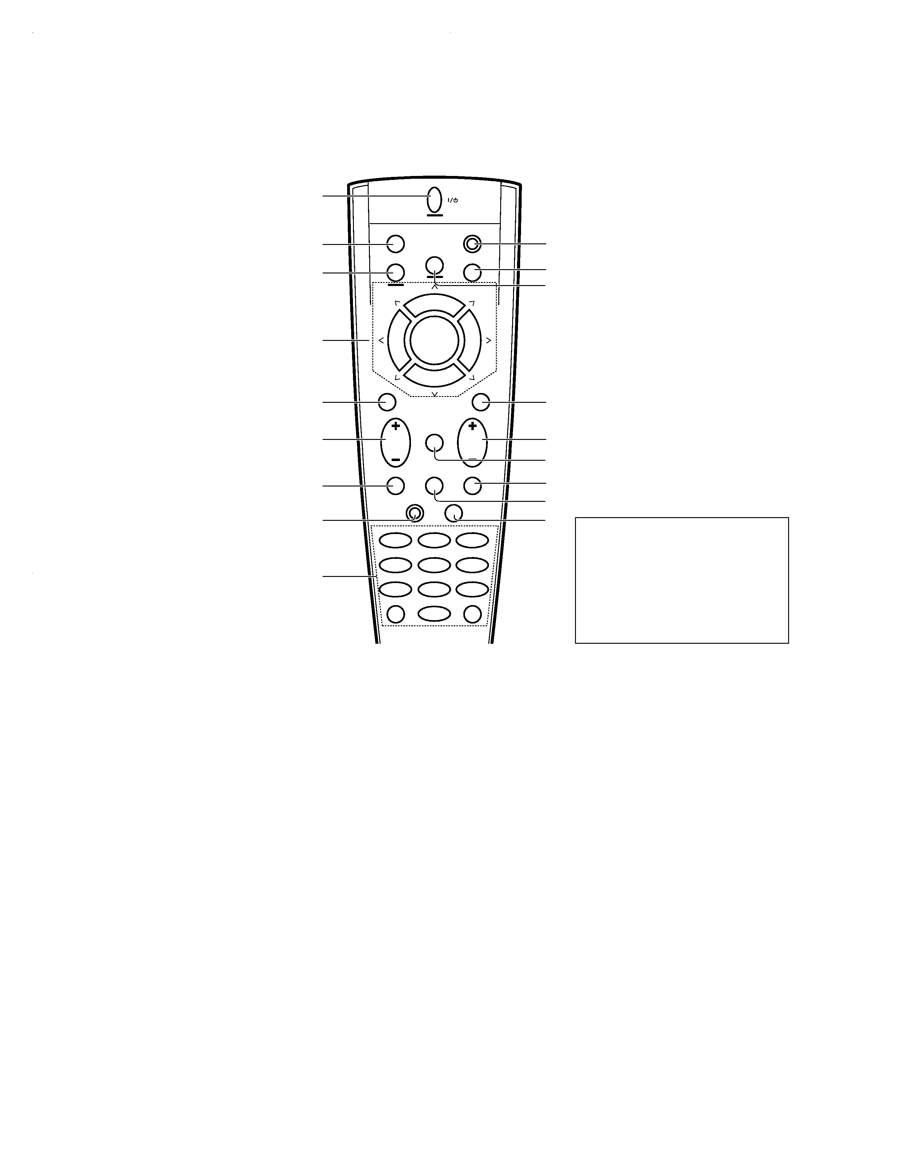
8 FUNCTION SHIFT key
Use in combination with the numeric keys
to execute alternate commands.
9 Numeric keys
Provide functions identical to those of the
original remote control supplied with the
component you are controlling.
To access the functions printed above the
keys, press within 3 seconds of pressing
the FUNCTION SHIFT key. Function avail-
ability varies for each component.
0 SHIFT key
Use in combination with the AUDIO and
VIDEO keys to change the remote control
mode without changing the input selector
or in combination with the POWER key to
turn on and off components programmed
into the remote control.
! TV selector key
Sets the remote control to operate a TV or
cable box. This key does not change the
input selector on the receiver.
@ AUDIO selector key
Selects the audio inputs and sets the re-
mote control to operate the respective
KENWOOD audio component.
If you connect audio components from
KENWOOD and other makers to the MD/
TAPE or CD jacks, you can set the remote
control to operate these components by
registering the appropriate setup code at
the respective input.
# GUIDE key
Use to activate the OSD menu functions of
registered components.
$ VOLUME key
Use to adjust the receiver volume.
% MUTE key
Use to temporarily mute the sound.
^ SOUND key
Use to adjust the sound quality and ambi-
ence effects.
& LISTEN MODE key
Use to select the listening mode.
* SETUP key
Use to select the surround sound settings.
1 POWER key
Use to turn the receiver on and off.
Use in combination with the input selector
(AUDIO, VIDEO, or TV) keys and SHIFT
key to turn various components on and off.
2 MACRO key
Use in combination with the AUDIO, VIDEO,
or TV keys to execute a series of com-
mands automatically (MACRO PLAY).
3 VIDEO selector key
Selects the video inputs and sets the re-
mote control to operate the component
registered at the respective input.
4 Multi control keys
Use to operate the selected component.
5 REC key
Use to operate the selected component.
6 TUNING/SKIP key
Use during the setup procedure to specify
various settings. Use to operate the tuner
or selected component.
7 SUBWOOFER key
Use in combination with the VOLUME +/
keys to adjust the volume of the subwoofer.
There are some cases in which keys (or
knobs) that have the same function on
the receiver and on the remote control
have different names. In the instruc-
tions of this manual, if the names of
corresponding keys (or knobs) on the
receiver and remote control are differ-
ent, the name of the remote control key
is indicated in parentheses.
AUDIO
SHIFT
MACRO
TV
VIDEO
GUIDE
REC
MUTE
VOLUME
TUNING/SKIP
THEME
FAV
MENU
FUNCTION
SHIFT
SETUP
INFO
ALT AUD
TV/SAT/VID
REPEAT
RANDOM
+100
DISPLAY
ENT
+10
LISTEN
MODE
SOUND
SUBWOOFER
23
1
56
4
89
7
0
1
2
3
7
8
9
4
5
6
0
!
#
^
*
&
%
@
$
8
7
4¢
6
BAND
P. CALL
P. CALL
POWER
KRF-V8010D/V8010DW
4
CONTROLS
KRF-V8010D(K)COVER1,1( 98.12.1017:51 y[W 7
KRF-V8010D/V8010DW
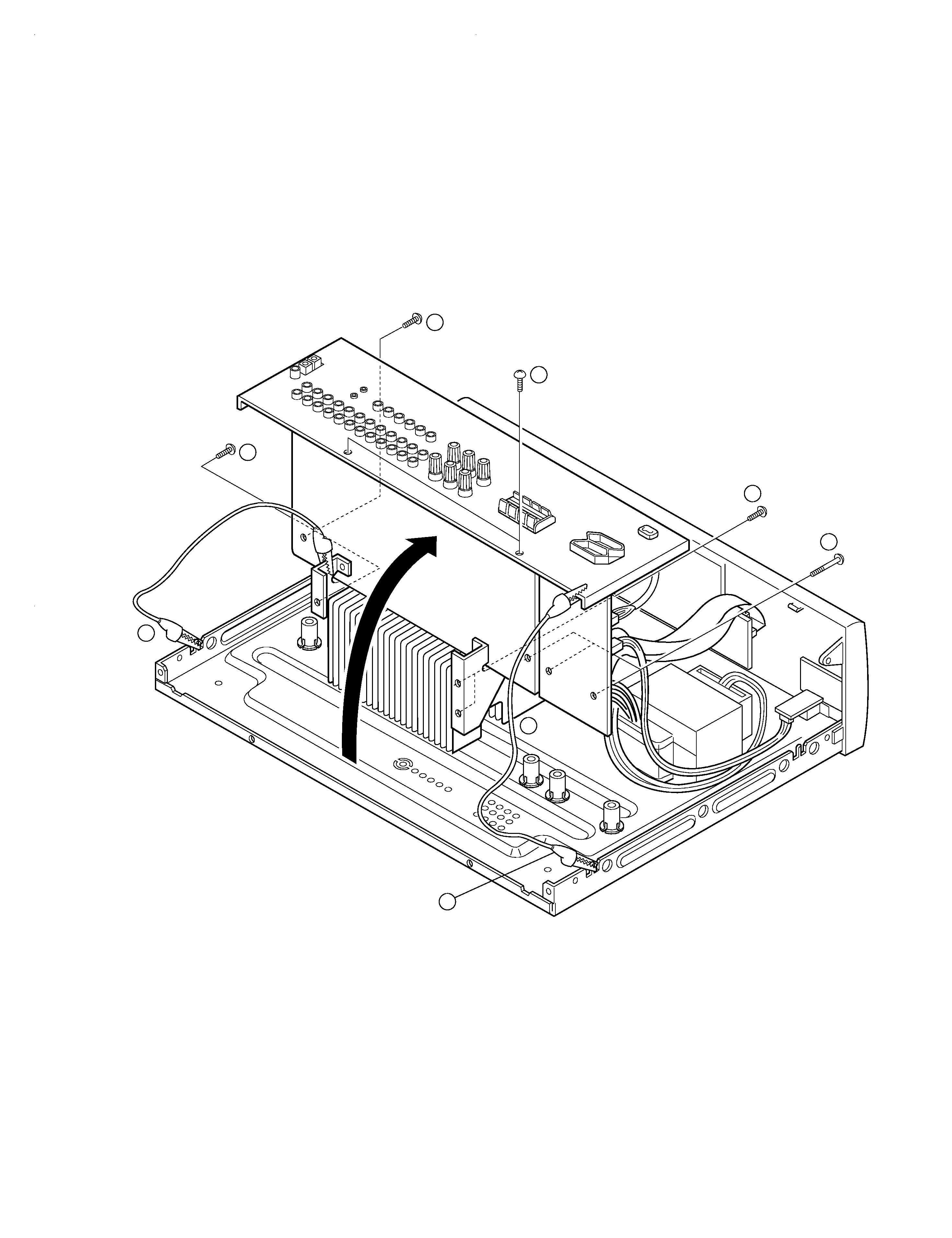
5
DISASSEMBLY FOR REPAIR
1. Remove the 8 screws (1,2,3),
remove the rear panel.
2. Connect the GND of the rear panel
and the chassis, the GND of the
mounting hardware and the chassis
with 2 alligators clip (4)
1
2
2
4
4
4
3
3
x2
x2
x3
KRF-V8010D(K)COVER1,1( 98.12.1017:51 y[W 12