SIZE AAA
BATTERY
(Not supplied)
50Wx4
K3i
DOLBY B-C NR
OFF
NF
DAB
AUD
VOL ADJ
REP
LOUD
PROG/PTY
4.5V
PREOUT
SCAN
B C NR
B S/RDM
MTL/M.RDM
EX
MENU
DISC
DISC
NAME
ANG
DISC
SRC
CLK
TI
KRC-PS979R System E's+
50Wx4
K3i
DOLBY B-C NR
OFF
NF
DAB
AUD
VOL ADJ
REP
LOUD
PROG/PTY
4.5V
PREOUT
SCAN
B C NR
B S/RDM
MTL/M.RDM
EX
MENU
DISC
DISC
NAME
ANG
DISC
SRC
CLK
TI
KRC-PS989R System E's+
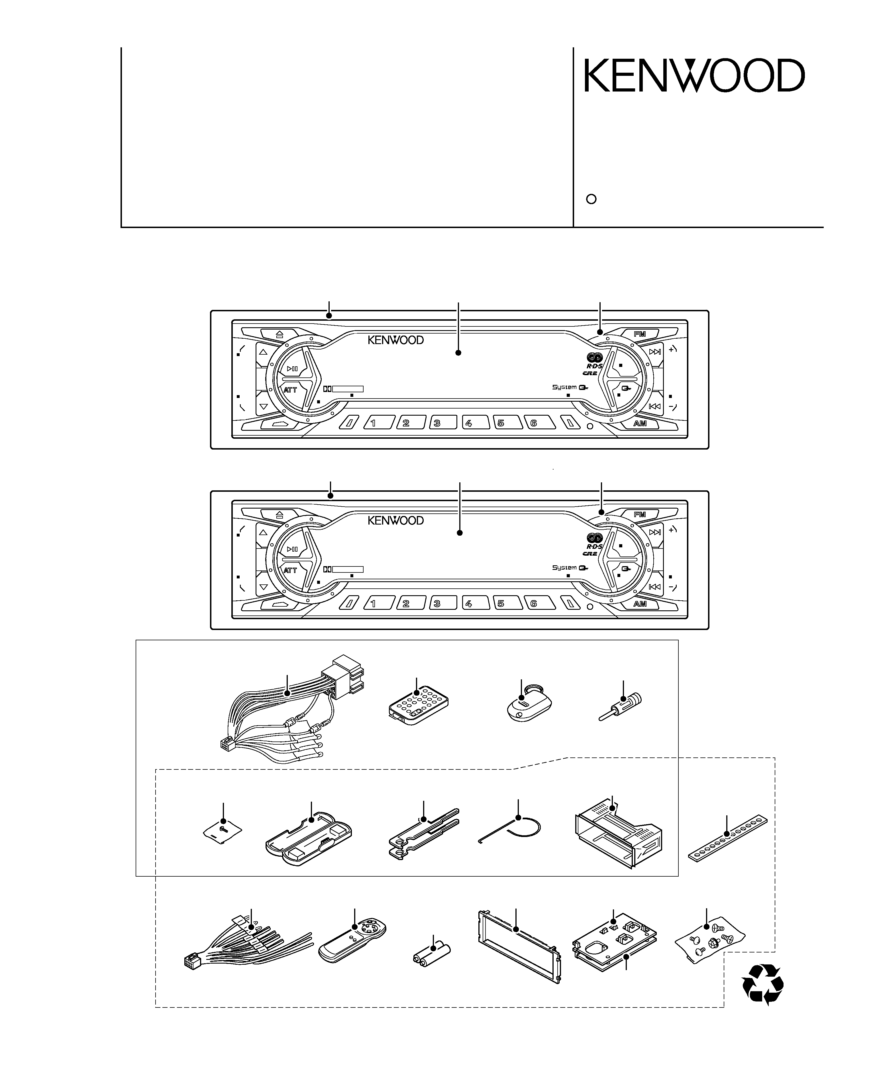
KRC-PS979R /PS989R
M&T CASSETTE RECEIVER
SERVICE MANUAL
C
2001-2 PRINTED IN KOREA
B51-7747-00 (K) 2162
KRC-PS979R
KRC-PS989R
The CASSETTE MECHANISM OPERATION DESCRIPTION is the same model D40-1122-05.
Please refer to the service manual for model D40-1122-05(B51-7452-00).
DC cord
(E30-4956-05)
Remote com. assy
(A70-2015-15)
Remote com. assy
(A70-0886-15)
Antenna adaptor
(T90-0523-05)
Screw set
(N99-1704-05)
Stay
(J54-0606-04)
Torsion coil spring
(G01-2924-04)
Lever
(D10-4562-04)x2
Mounting hardware
assy
(J21-9716-03)
Plastic cabinet assy
(A02-1497-03)
DC cord
(E30-4941-05)
Remote com. assy
(A70-0883-05)
Escutcheon assy
(B07-3010-02)
Bracket L
(J19-5051-03)
Screw set
(N99-1652-05)
Front glass
(B10-3240-01)
Escutcheon assy(ebony)
(B07-3006-03)
Panel assy
(A64-2133-02)
Front glass
(B10-3238-01)
Escutcheon assy(black)
(B07-3007-03)
Panel assy
(A64-2131-02)
CA-R66
MASK-key
RC-500
Bracket R
(J19-5052-03)
KRC-PS979R
KRC-PS989R
40%
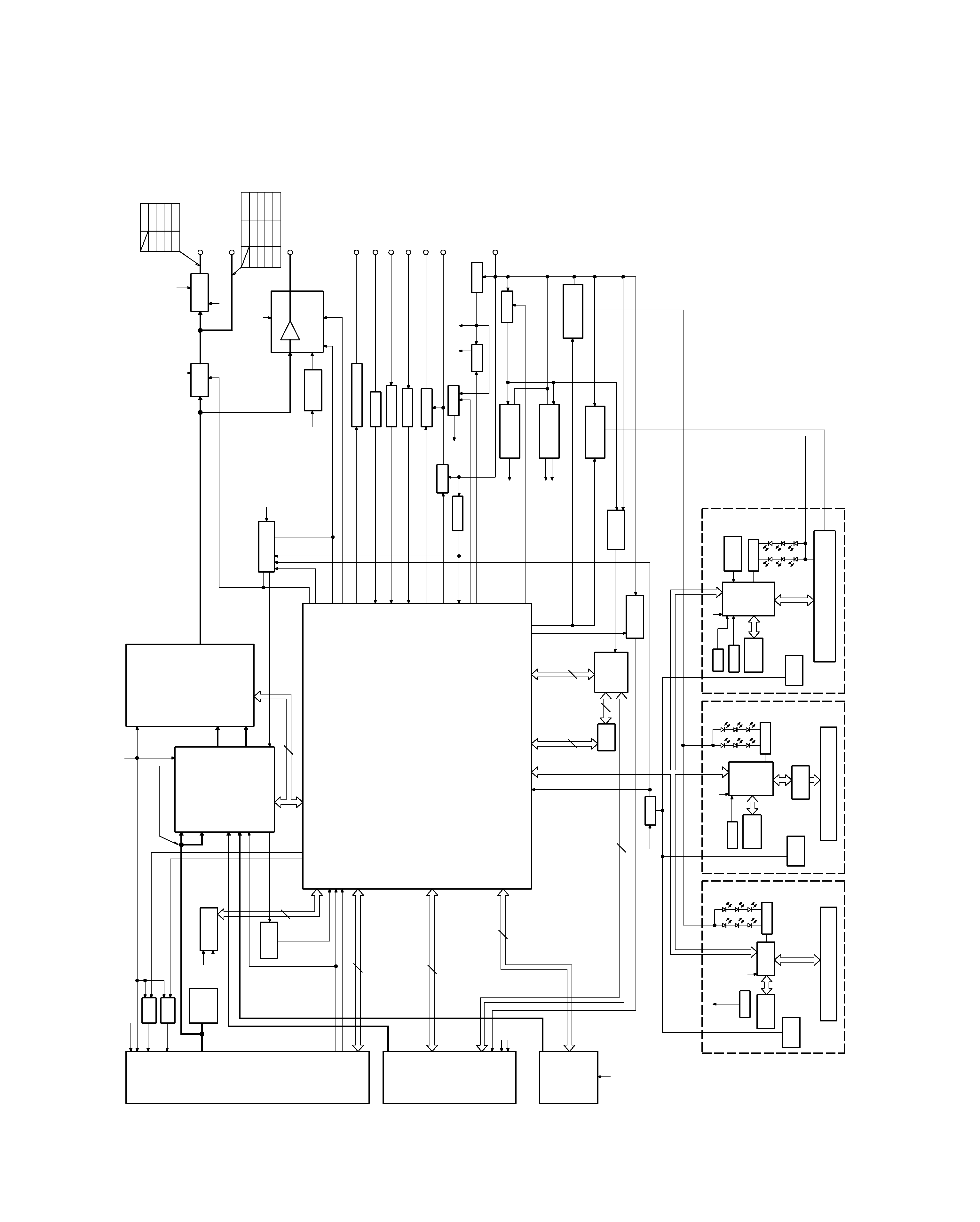
KRC-PS979R/PS989R
2
BLOCK
DIAGRAM
AUDIO
S-METER
AFC
IFC OUT
PLL DATA
PLL CLK
SW5V
FM
AM
TAPE
CHANGER
S METER
QUAL
SDA
SCK
S MUTE
A 8V
MODE 2
SUB-
MOT+B
SUB+
MODE 1
MS MODE
F/R
MUTE
MTL ON/OFF
BOLBY B/C
DOLBY ON/OFF
MS OUT
R REEL
F REEL
MODE 3
PACK IN
SRM
SW2
SRM
SW1
RCLK
QUAL
RDATA
NOISE
S METER
AFC
IFC OUT
PLL DATA
PLL CLK
MS OUT
MTL ON/OFF
MODE 2
MODE 3
R REEL
MODE 1
F REEL
MS MODE
F/R
MUTE
DOLBY ON/OFF
DATA C
CH RST
CH MUTE
DOLBY B/C
DATA H
CH CON
CH CLK
REQ H
REQ C
PACK IN
SRM
SW3
SRM
DET
RESET
SUB
MOT2
SUB
MOT1
SUB
MOT3
CASS/SRM
MOT
OR
ILL
ON
AM+B
FM+B
SCK
SDA
PRE MUTE
MUTE
BEEP
P MUTE
ACC DET
PHONE
DIMMER
EXT AMP CONT
P CON
PAN5V
P ON
ANT CONT
B.U DET
SW5V
SW5V
2
3
3
13
CH MUTE
CH RST
DATA H
DATA C
CH CON
REQ C
CH CLK
REQ H
BACK UP
8
1200mV
440mV
A 8V
SW5V
PANEL5V
PANEL5V
4
B.U.5V
PANEL5V
FL+B
FAC
4
2
SUB+
SUB-
2
SUB-
SUB+
SDA
SCK
MOT+B
FOR VFD
A8V
+B
-B
FOR 4.5V PRE
PAN5V
B.U.5V
SW5V
MUTE
AUX
IN
BACK UP
SW5V
B.U.5V
B.U.5V
+B
-B
CH
FM
1800mV
TAPE
AM
3600mV
855mV
1372mV
600mV
3600mV
1800mV
E TYPE K TYPE
1800mV
2250mV
1715mV
4500mV
1069mV
AM
CH
TAPE
FM
E TYPE
ILL
TEL MUTE
ACC
ANT CON
P CON
BACK UP
EXT.AMP CONT
F/E
FM+B
BUFFER
NOISE
BUFFER
DECODER
RDS
IC11
Q73
IC2
E-VOL
MPX
N.C.
AM+B
CASSETTE MECH
SYSTEM U-COM
IC1
CD-CHANGER
MD-CHANGER
KEY
MATRIX
RESET
SW
LCD
DRIVER
REMO
G/R SW
RESET
IC15
X13-996/999
SYSTEM u-COM
LCD TYPE
IC1
U-COM
MATRIX
SW
RESET
LCD
IC1
X13-995/998
KEY
REMO
PANEL
G/R SW
V-ILL TYPE
LCD
DRIVER
IC2
VFD(GRADATED)
SW
RESET
X13-994/997
REMO
MATRIX
KEY
G/R SW
U-COM
IC1
PANEL
FL(GRADATED) TYPE
ROM
SPEANA
BPF
DRIVER
SUB MOT
IC13
E S
SYSTEM
IC5
,
ONLY FL MODEL
MAIN MOT
+B
SUB MOT
+B
Q42
Q37,38
DC/DC
A1
ONLY FL MODEL
Q33,34
ILL AVR
ONLY FL MODEL
DC/DC
A 8V
Q20
IC6
SW14V
Q36
EXT AMP CONT
DIMMER
ACC DET
TEL MUTE
P CON
B.U DET
ANT CON
Q39
Q32
Q25
Q26
Q28
Q24
SW5V
B.U.5V
PAN5V
Q45
Q23
Q21,22
SRM
MECH
POWER IC
THEMO
PROTECT
IC4
IC10
MUTE LOGIC
DRIVER
MUTE
Q1-6
ONLY FL MODEL
4.5V
PRE AMP
IC7-9
SP OUT
1.8V PRE OUT
4.5V PRE OUT
LCD
251mV(ETYPE)
470mV(KTYPE)
FM:
AM:
230mV
KRC-PS979R
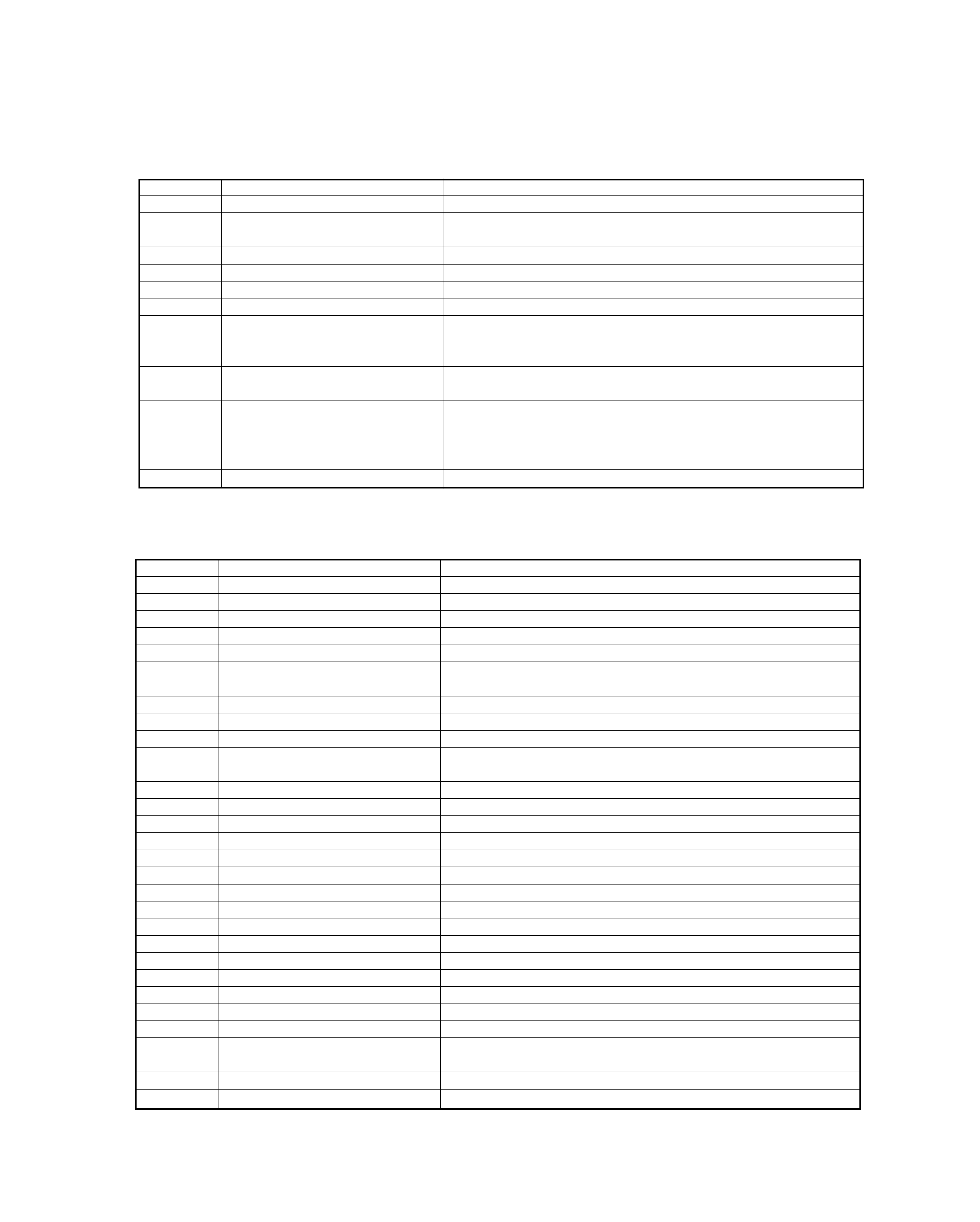
Component
Purpose · Function
Operation · Conditions · Compatibility
IC1
u-COM
IC2
E-VOL, MPX & NC
IC3
8 V AVR IC
IC4
Power IC
IC5
HPF & LPF Variation IC
IC6
4.5 V PRE-OUT Negative Power
Supply
IC7~9
4.5 V PRE-OUT Opamp
IC10
Muting Logic IC
IC11
RDS Decoder
IC13
Storage Mechanism/C-Mechanism
Motor Driver
IC15
Reset IC
IC16
Spectrum Analyzer AGC Opamp
Q1~6
Pre-Out Muting SW Tr.
Switches PRE-OUT muting ON when the base is "H".
Q19
8 V Power SW Tr.
Turns ON when the base is "H".
Q20
8 V Power Tr.
Q22, 21
B-U 5 V Power Tr.
Q23
SW 5V SW Tr.
Turns ON when the base is "L".
Q24
B-U Detection Tr.
Back-Up voltage is detected when the base is "H".
Q25
Acc Detection Tr.
Acc voltage is detected when the base is "H".
Q28,29,30,31 P-CON SW.
Q32
Dimmer Detection Tr.
Dimmer ON is detected when the base is "H".
Q35
SW14 SW Tr.
Turns ON when the base is "H".
Q36, 37
Motor Driver Tr.
Q39
External Amp Control
Q41,42
C-Mechanism Main Motor Power Tr.
Turns ON when the base is "H".
Q43
Storage Mechanism/C-Mechanism
Switches to the cassette mechanism motor voltage when the base is
Motor Power Tr.
"H", or the storage mechanism motor voltage when it is "L".
Q45
Panel 5 V SW Tr.
Turns ON when the base is "L".
Q55, 56
4.5 V PRE Negative Power Reg.
Turns ON when the base of Q55 is "H".
KRC-PS979R/PS989R
3
COMPONENTS DESCRIPTION
Component
Purpose · Function
Operation · Conditions · Compatibility
IC1
Panel u-COM
IC2
Spectrum Analyzer IC
IC3
Remote Control IC
IC4
ROM
IC5
3.3 V Regulator
Power supply for the 3.3 V drive IC and FL tubes (logic).
IC6
Buffer IC
Converts 5.0 V to 3.3 V.
Q2
IC2/3 Power ON/OFF SW
Switches power OFF when the base is "H", or ON when the base is "L".
FL Tube VDD1/VDD2 Timing
When the base of Q5 is "H", IC3 is activated to switch FL tube VDD1
Q3, 5
Adjustment & Panel u-COM SC CON ON and SC CON ON. When it is "L", FL tube VDD1 and SC CON are
ON/OFF SW
both OFF.
Q4
FL BLK Signal Logic Inverter & 5.0 V
to 3.3 V Converter
Q6, 7
Key Illumination SW
Turns green illumination ON when the base of Q6 is "H" or OFF
when it is "L".
Turns red illumination ON when the base of Q7 is "H" or OFF
when it is "L".
Q8
SRC Key Illumination ON/OFF SW
Turns illumination ON when the base is "H" or OFF when it is "L".
(X13-9940-10)
(X14-6420-20)
(X14-6432-70)
KRC-PS979R/PS989R
4
COMPONENTS DESCRIPTION
Component
Purpose · Function
Operation · Conditions · Compatibility
IC1
Playback EQ, Dolby & Blank Detection
Q1
Constant Switching in Blank Detection
Switches the time constant according to the PLAY or FF/REW mode.
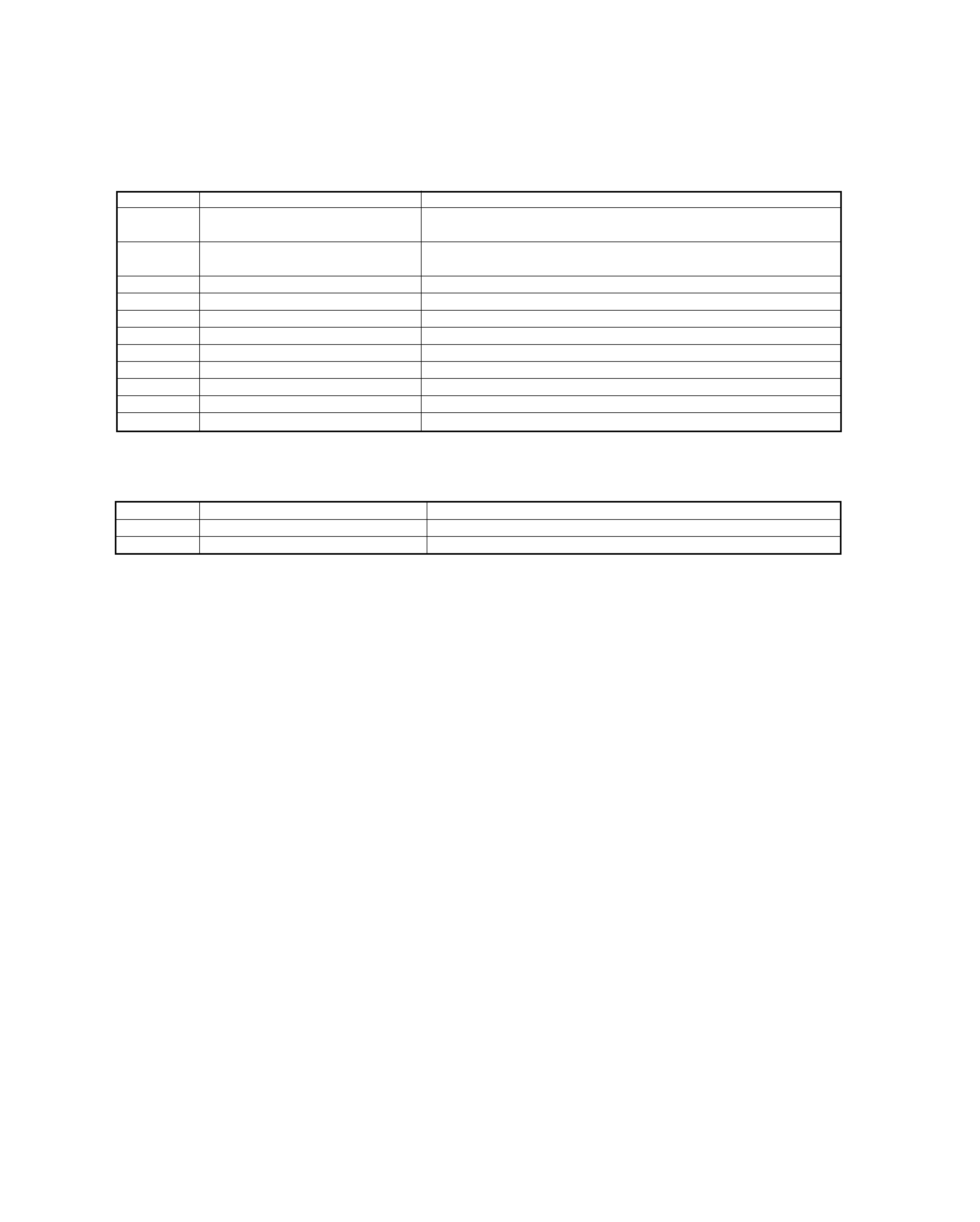
Component
Purpose · Function
Operation · Conditions · Compatibility
Q57, 58, 59
4.5 V PRE Negative Power
Differential Amp Tr.
Q60, 61, 62
4.5 V PRE Positive Power
Differential Amp Tr.
Q71
PRE-Out Muting Driver Tr.
Turns PRE-OUT muting ON when the base is "L".
Q72
E-VOL Muting SW Tr.
Turns Electronic Volume muting ON when the base is "H".
Q73
Noise Detection Buffer
Q86, 88
AM +B SW Tr.
Switches AM +B ON when the base of Q86 is "H".
Q87, 89
FM +B SW Tr.
Switches FM +B ON when the base of Q87 is "H".
Q90
Composite Buffer
Q402
DC/DC Power SW Tr.
Turns ON when the base is "H".
Q403,404
DC/DC Power Tr.
Q405
Spectrum Analyzer AGC Tr.
(X87-3020-20)
(X87-3032-70)
(X14-6420-20)
(X14-6432-70)
KRC-PS979R/PS989R
5
MICROCOMPUTER'S TERMINAL DESCRIPTION
Pin
Name
I/O
Purpose
Operation Description
1
DATA1
O
DATA communication with FL driver.
2
CLK
O
CLK communication with FL driver.
(Data shift at positive going)
3
NC
I
No connection.
4
DATA2
O
DATA communication with FL driver.
5
CLK IN
I
CSI2 serial clock input.
(For sync between Data 1 and 2)
6
EVDD
-
PAN. 5 V
7
EVSS
-
Ground.
8
RED
O
Illumination RED switching.
H: ON, L: OFF
9
GREEN
O
Illumination GREEN switching
H: ON, L: OFF
10
REMO
I
Input from Remote Control IC.
11
LATCH
O
Latch for FL driver.
12
GCP
O
Illumination gradation control.
13
REMO ON
O
Remote Control IC power ON/OFF.
H: ON, L: OFF
14-16
A13-15
O
Address.
17
BLK
O
Display for FL driver.
Blanking display.
H: Display ON, L: Display OFF
18
TEST
I
Internally connected.
19-30
A5-12,A1-4
O
Address.
31
RESET
I
Reset.
L: Reset, H: Reset released
32
TX1
-
Grounded.
33
TX2
O
34
REGC
-
Regulator stabilizing capacitance connection.
35
X2
-
Main clock.
36
X1
-
Main clock.
37
VSS
-
Grounded.
38
VDD
-
PAN. 5V.
39-42
NC
O
No connection.
43
OE
O
Output Enable.
44
CE
O
Chip Enable.
45
NC
O
No connection.
46
BLUE
O
BLUE LED ON/OFF.
H: ON, L: OFF
47-54
AD0-7
I
DATA for external ROM.
55
BVDD
-
PAN. 5 V.
56
BVSS
-
Grounded.
57-64
AD8-15
I
DATA for external ROM.
65-68
A16-19
O
Address.
69
-
O
No connection.
70
A20
O
Address. PAN. 5 V.
71
AVDD
-
PAN. 5V.
72
AVSS
-
Grounded.
73
AVREF
-
74
F01
I
BPF (63Hz)
75
F02
I
BPF (150Hz)
76
F03
I
BPF (330Hz)
77
F04
I
BPF (1kHz)
78
F05
I
BPF (3.3kHz)
79
F06
I
BPF (10kHz)
80
WAVE IN
I
Audio input.
81-85
KR5-1
I
KEY RETURN
86
SC REQ
O
Request communication with System Controller.
87
NC
O
No connection.
88
SC
CON
I
Panel u-COM control.
During operation: H
89
OPEN
I
OPEN KEY
H: ON, L: OFF
UPD703033GC058 (IC1: X13)
Panel MicroComputer