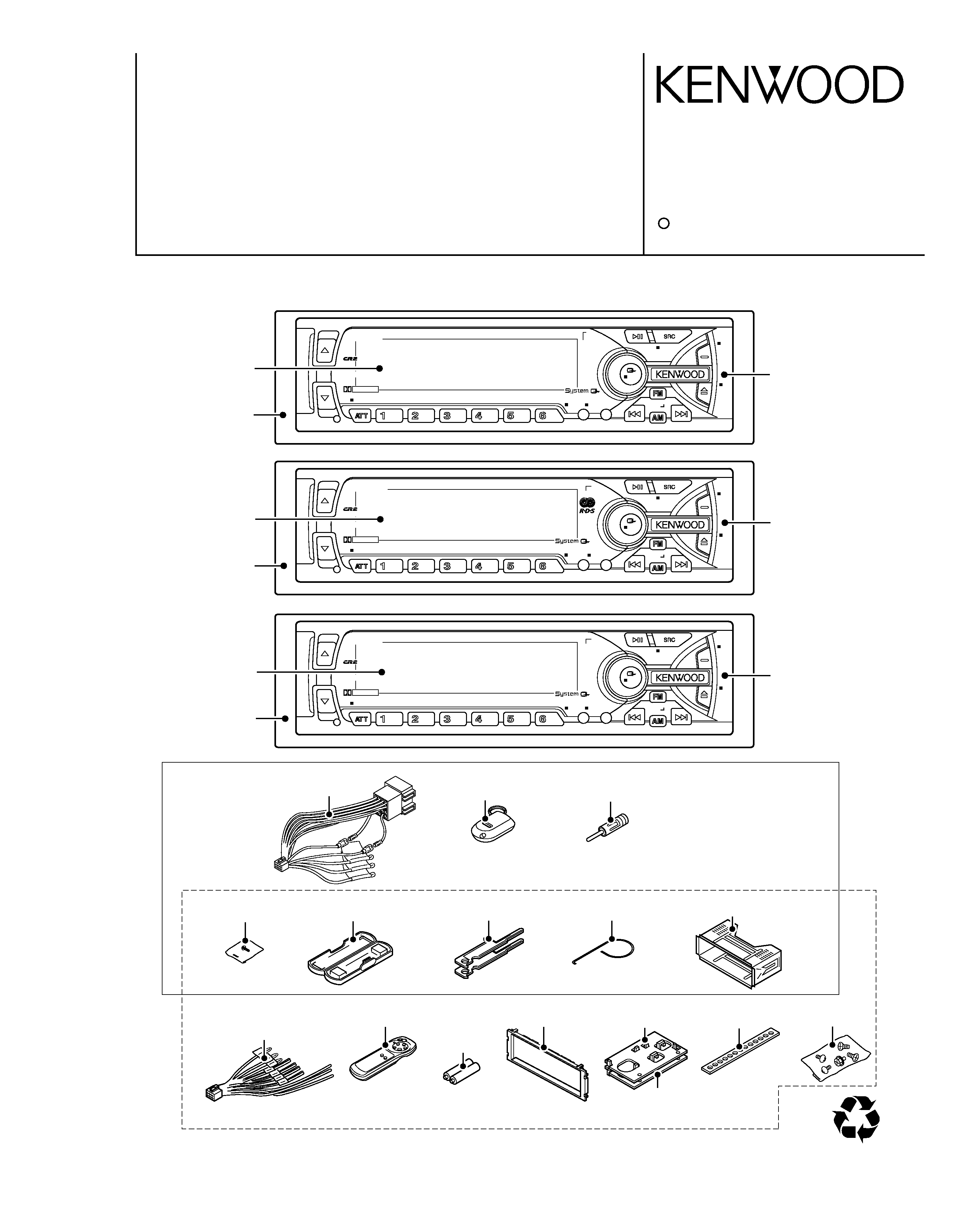
KRC-709
B NR
LOUD
SCAN
B.S/RDM
REP
MTL/M.RDM
DISP
NAME.S
AUTO
AME
AUD
PROG
DAB
ANG
MENU
CLK
PWR OFF
47Wx4
DOLBY B NR
KRC-779R
B NR
LOUD
SCAN
B.S/RDM
REP
MTL/M.RDM
DISP
NAME.S
TI
VOL ADJ
AUD
PROG/PTY
DAB
ANG
MENU
CLK
PWR OFF
47Wx4
DOLBY B NR
EX
K3i
KRC-889
B NR
LOUD
SCAN
REP
MTL/M.RDM
DISP
NAME.S
AUTO
AME
AUD
PROG
DAB
ANG
MENU
CLK
PWR OFF
47Wx4
DOLBY B NR
EX
B.S/RDM
SIZE AAA
BATTERY
(Not supplied)
KRC-709/779R/RY/889
M&T CASSETTE RECEIVER
SERVICE MANUAL
C
2001-2 PRINTED IN KOREA
B51-7749-00 (K) 3395
KRC-709
The CASSETTE MECHANISM OPERATION DESCRIPTION is the same model D40-1122-05.
Please refer to the service manual for model D40-1122-05(B51-7452-00).
DC cord
(E30-4942-05)
Remote com. assy
(A70-0886-15)
Antenna adaptor
(T90-0523-05)
Screw set
(N99-1704-05)
Stay
(J54-0606-04)
Torsion coil spring
(G01-2924-04)
Lever
(D10-4562-04)x2
Mounting hardware assy
(J21-9716-03)
Plastic cabinet assy
(A02-1497-03)
DC cord
KRC-709:(E30-4940-05)
KRC-889:(E30-4939-05)
Remote com. assy
(A70-0883-05)
Escutcheon assy
(B07-3010-02)
Bracket L
(J19-5051-03)
Screw set
(N99-1652-05)
Front glass
(B10-3237-01)
Escutcheon assy
(B07-3007-03)
Panel assy
(A64-2130-02)
MASK-key
RC-500
Bracket R
(J19-5052-03)
KRC-779R/RY
KRC-709,889
KRC-779R/RY
KRC-889
Front glass
(B10-3242-01)
Front glass
(B10-3239-01)
Panel assy
(A64-2134-02)
Panel assy
(A64-2132-02)
Escutcheon assy
(B07-3007-03)
Escutcheon assy
(B07-3007-03)
40%
KRC-709,779R/R
Y,889
2
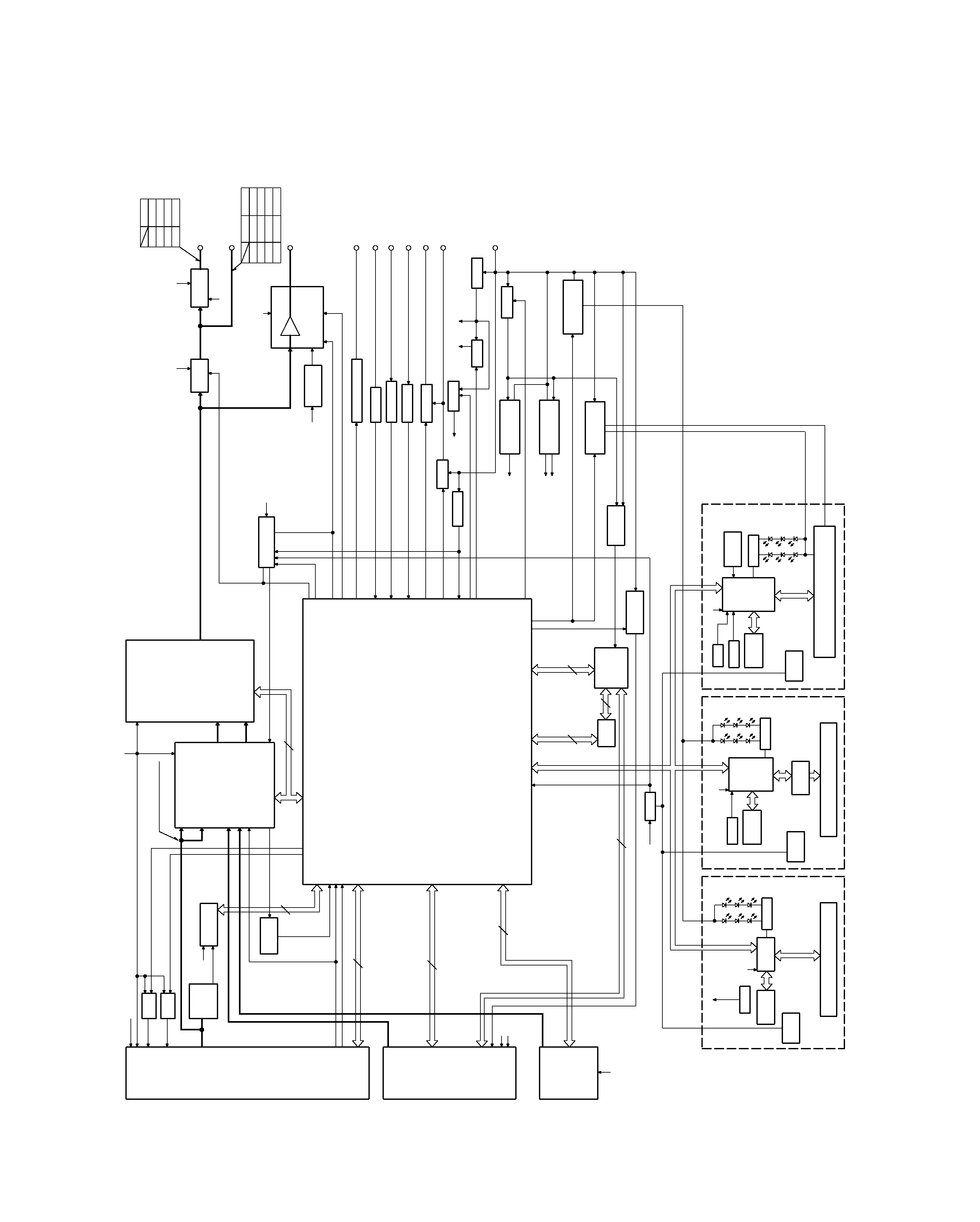
BLOCK
DIAGRAM
AUDIO
S-METER
AFC
IFC OUT
PLL DATA
PLL CLK
SW5V
FM
AM
TAPE
CHANGER
S METER
QUAL
SDA
SCK
S MUTE
A 8V
MODE 2
SUB-
MOT+B
SUB+
MODE 1
MS MODE
F/R
MUTE
MTL ON/OFF
BOLBY B/C
DOLBY ON/OFF
MS OUT
R REEL
F REEL
MODE 3
PACK IN
SRM
SW2
SRM
SW1
RCLK
QUAL
RDATA
NOISE
S METER
AFC
IFC OUT
PLL DATA
PLL CLK
MS OUT
MTL ON/OFF
MODE 2
MODE 3
R REEL
MODE 1
F REEL
MS MODE
F/R
MUTE
DOLBY ON/OFF
DATA C
CH RST
CH MUTE
DOLBY B/C
DATA H
CH CON
CH CLK
REQ H
REQ C
PACK IN
SRM
SW3
SRM
DET
RESET
SUB
MOT2
SUB
MOT1
SUB
MOT3
CASS/SRM
MOT
OR
ILL
ON
AM+B
FM+B
SCK
SDA
PRE MUTE
MUTE
BEEP
P MUTE
ACC DET
PHONE
DIMMER
EXT AMP CONT
P CON
PAN5V
P ON
ANT CONT
B.U DET
SW5V
SW5V
2
3
3
13
CH MUTE
CH RST
DATA H
DATA C
CH CON
REQ C
CH CLK
REQ H
BACK UP
8
1200mV
440mV
A 8V
SW5V
PANEL5V
PANEL5V
4
B.U.5V
PANEL5V
FL+B
FAC
4
2
SUB+
SUB-
2
SUB-
SUB+
SDA
SCK
MOT+B
FOR VFD
A8V
+B
-B
FOR 4.5V PRE
PAN5V
B.U.5V
SW5V
MUTE
AUX
IN
BACK UP
SW5V
B.U.5V
B.U.5V
+B
-B
CH
FM
1800mV
TAPE
AM
3600mV
855mV
1372mV
600mV
3600mV
1800mV
E TYPE K TYPE
1800mV
2250mV
1715mV
4500mV
1069mV
AM
CH
TAPE
FM
E TYPE
ILL
TEL MUTE
ACC
ANT CON
P CON
BACK UP
EXT.AMP CONT
F/E
FM+B
BUFFER
NOISE
BUFFER
DECODER
RDS
IC11
Q73
IC2
E-VOL
MPX
N.C.
AM+B
CASSETTE MECH
SYSTEM U-COM
IC1
CD-CHANGER
MD-CHANGER
KEY
MATRIX
RESET
SW
LCD
DRIVER
REMO
G/R SW
RESET
IC15
X13-996/999
SYSTEM u-COM
LCD TYPE
IC1
U-COM
MATRIX
SW
RESET
LCD
IC1
X13-995/998
KEY
REMO
PANEL
G/R SW
V-ILL TYPE
LCD
DRIVER
IC2
VFD(GRADATED)
SW
RESET
X13-994/997
REMO
MATRIX
KEY
G/R SW
U-COM
IC1
PANEL
FL(GRADATED) TYPE
ROM
SPEANA
BPF
DRIVER
SUB MOT
IC13
E S
SYSTEM
IC5
,
ONLY FL MODEL
MAIN MOT
+B
SUB MOT
+B
Q42
Q37,38
DC/DC
A1
ONLY FL MODEL
Q33,34
ILL AVR
ONLY FL MODEL
DC/DC
A 8V
Q20
IC6
SW14V
Q36
EXT AMP CONT
DIMMER
ACC DET
TEL MUTE
P CON
B.U DET
ANT CON
Q39
Q32
Q25
Q26
Q28
Q24
SW5V
B.U.5V
PAN5V
Q45
Q23
Q21,22
SRM
MECH
POWER IC
THEMO
PROTECT
IC4
IC10
MUTE LOGIC
DRIVER
MUTE
Q1-6
ONLY FL MODEL
4.5V
PRE AMP
IC7-9
SP OUT
1.8V PRE OUT
4.5V PRE OUT
LCD
251mV(ETYPE)
470mV(KTYPE)
FM:
AM:
230mV
KRC-709,779R/RY,889
Component
Purpose · Function
Operation · Conditions · Compatibility
IC1
System u-com
IC2
E-VOL, N.C, MPX
IC3
Regulator IC for Audio 8V
IC4
Power IC
IC10
Mute logic IC
IC11
RDS decoder
IC13
Motor driver IC
IC15
Reset IC
Q1~4
PRE OUT MUTE SW
Pre outs are muted when the base goes "H".
Q18~20
Audio 8V AVR
Inverted darlington connection
Q20 is turned ON when Q18's base goes "H".
Q21, 22
B.U 5V AVR
Inverted darlington connection
Q22 is turned ON when Q21's base goes "H".
Q23
SW 5V
ON when the base goes "L".
Q24
B.U detection
ON when the base goes "H" during B.U applied.
Q25
ACC detection
ON when the base goes "H" during ACC applied.
Q26, 27
P-ANT SW
Q26 is turned ON when Q27's base goes "H".
Q28~31
P-CON SW
Q28 is turned ON when Q31's base goes "H".
Q32
Dimmer SW
ON when the base goes "H" while vehicle small lamps turn on.
Q33, 34, 44
Illumination AVR
ON when Q44's base goes "H".
Q36
SW 14V
ON when base goes "H".
Q37, 38
Motor driver supply
Q38 is turned ON when Q37's base goes "H".
Q39
External Amp Control
ON when the base goes "L".
Q41, 42
Cassette mecha main motor
Q42 is turned ON when Q41's base goes "H".
supply SW
Q43
Motor driver's voltage SW
Base "H" ··· cassette mecha's submotor
Base "L" ··· mask mecha's motor.
Q45, 46
Panel 5V SW
Q45 is turned ON when Q46's base goes "H".
Q71
Pre out mute driver
ON when the base goes "L".
Q72
E-VOL Mute SW
ON when the base goes "H".
Q73
Noise buffer
Q85
IFC out buffer
Q86, 88
AM+B SW
Q88 is turned ON when Q86's base goes "H".
Q87, 89
FM+B SW
Q89 is turned ON when Q87's base goes "H".
Q90
Composite out buffer
KRC-709,779R/RY,889
3
COMPONENT DESCRIPTION
(X14-644x-xx)
(X14-6452-73)
Component
Purpose · Function
Operation · Conditions · Compatibility
IC1
LCD Driver with Key Matrix
IC2
Remote Control IC
Q2
Key Detection SW
Q2 starts key scan in M&T.
Q3, 4
Key Illumination SW
Lights key illumination in Red when the base of Q3 is ON.
Lights key illumination in Green when the base of Q4 is "H"
Q5
VLCD Reference Voltage Supply
Constant voltage circuit.
Q6
Remote Control IC Power Supply
Activates remote control when the base of Q6 is "L"
Q7
Dimmer SW
The base of Q7 is normally "H" but becomes "
" when DIMMER is ON.
(X13-9960-10)
(X13-9992-73)
(X87-3022-71)
(X87-3032-73)
Component
Purpose · Function
Operation · Conditions · Compatibility
IC1
Playback EQ, Dolby & Blank Detection
Q1
Constant Switching in Blank Detection
Switches the time constant according to the PLAY or FF/REW mode.

KRC-709,779R/RY,889
4
MICROCOMPUTER'S TERMINAL DESCRIPTION
Pin
Name
I/O
Purpose
Operation Description
1
AM+B
O
AM power supply terminal.
During AM operation: H.
2
FM+B
O
FM power supply terminal.
During FM operation: H.
Last FM with RDS model: H
3
AFS
O
Constant switching when noise is detected.
During FM seek or AM search: L.
During reception: H.
4
PLL-DATA
I/O DATA input/output terminal from/to F/E.
5
PLL-CLK
I/O CLOCK input/output terminal from/to F/E.
6
Evdd
-
Positive power supply terminal.
7
GND
-
Grounding terminal.
8
N.C
O
No connection.
9
BEEP
O
Beep output terminal.
10
REMO
I
Remote control input terminal.
11
P-ON
O
SW 14 V control terminal.
Power ON: H. Power OFF: L.
12
P-STBY
O
Power IC STBY terminal control.
Power IC OFF: L. Power IC ON: H.
During reset: Input.
13
IC2-SDA
I/O IC2 DATA line.
14
IC2-SCK
O
IC2 CLOCK line.
15
P-MUTE
O
Power IC muting terminal.
Power OFF: L. All OFF: L.
During TEL muting: L.
16
PRE-MUTE
O
Pre-Out muting terminal.
During momentary power down: L.
17
DIMMER CON
O
Dimmer control.
DIMMER: Pulse control.
DIMMER OFF: H.
18
TEST
-
Test pin.
19
P-CON
O
Power control terminal.
Power ON: H. Power OFF: L.
20
ANT-CON
O
Antenna control terminal.
TUNER, TI ON: H
ON: Open. OFF: L.
21
MUTE
O
Muting terminal.
The time constant is 0.48 ms with all
models.
22
N.C
O
No connection.
23
ACC-DET
I
Acc detection terminal.
Acc detected: L. Acc not detected: H.
24
DIMMER
I
Small detection terminal.
ON: L. OFF: H.
25
SW-5V
O
5 V power supply terminal.
ON: L. OFF: H.
26
CH-MUTE
I
Muting request from CH.
ON: H. OFF: L.
27
CH-CON
O
CH control output.
ON: H. OFF: L.
28
CH-REQH
O
Request output to CH.
Requested: L.
Normal: L. When the system is
29
CH-RST
O
Reset output to CH.
reset,turns H then L in 400 ms after
recovery from reset.
L 40 ms: Bass boost OFF.
30
EXT-AMP-CONT
O
External amplifier control terminal (In 200 ms).
L 70 ms: Bass boost LOW.
L 100 ms: Bass boost HIGH.
31
RESET
I
Reset input terminal
Normal: H. Reset: L.
32
XT1
I
Sub-clock connection terminal.
The clock count is active even when
Power is OFF.
33
XT2
-
Sub-clock connection terminal.
34
REGC
-
Output terminal for the capacitor in the
regulator in u-COM.
Power ON: Oscillated.
35
X2
-
Main clock connection terminal.
Power OFF or momentary power
down: Oscillation stopped.
UPD703033GC050 (IC1: X14)
SYSTEM MICROCOMPUTER

KRC-709,779R/RY,889
5
MICROCOMPUTER'S TERMINAL DESCRIPTION
Pin
Name
I/O
Purpose
Operation Description
36
X1
I
Main clock connection terminal.
37
Vss
-
Grounding terminal.
38
Vdd
-
Positive power supply terminal.
39
CLKOUT
O
Internal System Clock output.
40
N.C
O
No connection.
41
MOTOR
O
Cassette mechanism main motor
When the motor is running: H.
output terminal.
When it is stopped: L.
42
MODE3
I
Cassette mechanism mode detection terminal.
43
MODE1
I
Cassette mechanism mode detection terminal.
44
MODE2
I
Cassette mechanism mode detection terminal.
45
N.C
O
Outputs Low. No connection.
46
SUB1
O
Sub-motor output terminal (1).
47
SUB2
O
Sub-motor output terminal (2).
48
SUB3
O
Sub-motor output terminal (3).
49
CAS/SRM
O
Cassette mechanism/SRM mechanism
Cassette mechanism: H.
voltage switching terminal.
SRM mechanism: L.
50
N.C
O
Outputs Low. No connection.
51
N.C
O
Outputs Low. No connection.
52
ILL-ON
O
FL +B output terminal.
ON: H, OFF: L
53
PAN-5V
O
Panel 5 V control terminal.
54
N.C
O
Outputs Low. No connection.
55
BVdd
-
Positive power supply terminal.
56
BVss
-
Grounding terminal.
57
TYPE1
I
Destination type switching port.
58
TYPE0
I
Destination type switching port.
59
N.C
O
Outputs Low. No connection.
60
N.C
O
Outputs Low. No connection.
61
ST TYPE1
I
IC2 destination type terminal.
Default: L.
62
ST TYPE0
I
IC2 destination type terminal.
Default: L.
63
SRM-SW1
I
Panel position detection switch 1.
Normal: H. Reset: L. Panel detached: L.
64
PAN-RESET
O
Reset output to Panel u-COM.
Momentary power down: L.
Microcomputer overrun: L.
65
L CE
I/O CE terminal for LCD driver.
66
SRM-SW3
I
Panel position detection switch 3.
67
SRM-SW2
I
Panel position detection switch 2.
68
FWD/REV
O
TAPE EQ input switching terminal.
FWD: L. REW: H.
During TAPE PLAY: H.
Constant switching terminal in case
During TAPE FF/REW or other than
69
MS-CONT
I/O
TAPE input: L.
of blank detection.
Cassette mechanism detected: L.
Cassette mechanism not detected: H.
70
AVCONT
O
AD reference voltage control output.
Same timing as P-ON. H during
operation.
71
Avdd
-
Positive power supply terminal.
72
Avss
-
Grounding terminal.
73
Avref
I
Reference voltage supply terminal for
A/D converter.
74
PHONE
I
PHONE detection terminal.
TEL MUTE: No more than 1 V.
NAVI MUTE:2.5 V or more.
75
R-REEL
I
Cassette mechanism reel pulse input (REV).
Vth = 2.5 V.
UPD703033GC050 (IC1: X14)
SYSTEM MICROCOMPUTER